A feature interaction is some way in which a feature or features modify or in uence another ..... know what is on the other end of its calls, for example, whether a far port is ...... munications and Software Systems V. IOS Press, Amsterdam, 1998.
This is page 1 Printer: Opaque this
An Experiment in Feature Engineering Pamela Zave
ABSTRACT Feature-oriented speci cations must be constructed, validated, and veri ed di�erently from other speci cations. The crucial step is determining how features should interact.
1 Feature-Oriented Speci cation A feature of a software system is an optional or incremental unit of functionality. A feature-oriented speci cation is organized by features. It consists of a base speci cation and feature modules, each of which speci es a separate feature. The behavior of the system as a whole is determined by applying a feature-composition operator to these modules. A feature interaction is some way in which a feature or features modify or in uence another feature in de ning overall system behavior. Formally this in uence can take many forms, depending on the nature of the featurespeci cation language and composition operator. A group of logical assertions, composed by conjunction, can a�ect each other's meanings rather di�erently than a group of nite-state machines, composed by exchanging messages on bu�ered communication channels. In general, features might interact by causing their composition to be incomplete, inconsistent, nondeterministic, or unimplementable in some speci c sense.1 Or the presence of a feature might simply change the meaning of another feature with which it interacts. Feature-oriented speci cation emphasizes individual features and makes them explicit. It also de-emphasizes feature interactions, and makes them implicit. Feature-oriented speci cation is widely popular because it makes speci cations easy to change and individual features easy to understand. Feature-oriented speci cation is also easy to abuse by ignoring feature interactions altogether. Although the feature-oriented style of system description presents many challenges to formal methods, it cannot be ignored because it is too attrac1 For example, in TLA [1] the result of feature composition could fail to be machineclosed. The speci cation would be unimplementable because it requires the system to control the environment's choices.
2
Pamela Zave
tive to the majority of people who actually describe systems. For example, it is ubiquitous in the telecommunication industry (where the usual featurespeci cation language is English, and the usual composition operator is concatenation). As a result of this situation, problems of unmanageable feature interactions a�ect all segments of the telecommunication industry, and are the primary motivation for the industry's interest in formal methods [2, 4, 5, 8, 3]. Two points about feature interactions are frequently misunderstood. Since these misunderstandings make it impossible to talk about feature interaction clearly, let alone formally, it is important to emphasize these points at the outset: � While many feature interactions are undesirable, many others are desirable or necessary. Not all feature interactions are bad! � Feature interactions are an inevitable by-product of feature modularity. \Busy treatments" in telephony are features for handling busy situations. They exemplify these points. Suppose that we have a feature-speci cation language in which a busy treatment is speci ed by providing an action, an enabling condition, and a priority. Further suppose that a special featurecomposition operator ensures that, in any busy situation, the action applied will be that of the highest-priority enabled busy treatment. In a busy situation where two busy treatments 1 and 2 are both enabled, with 2 having higher priority, these features will interact: the action of 1 will not be applied, even though its stand-alone speci cation says that it should be applied. This feature interaction is intentional and desirable. It is a by-product of the feature modularity that allows us to add busy treatments to the system without changing existing busy treatments. Without the special composition operator, when 2 is added to the system, the enabling condition 1 of 1 must be changed to 1 ^ : 2 . B
B
B
B
B
E
B
E
E
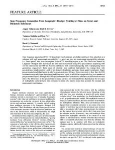
2 The Challenge of Feature Engineering I am interested in helping people write good feature-oriented formal speci cations, a process I dub feature engineering. Figure 1 is a simple picture of how feature engineering might be done. It assumes that a base speci cation and old features already exist, and that the goal is to add new features to this legacy. To realize the process, we shall have to rise to many challenges. First and foremost is the need for a truly modular formalism. A modular formalism would facilitate and support the process of Figure 1 as follows: � It would be possible to specify almost any increment of functionality as an independent feature.
1. An Experiment in Feature Engineering
base specification, old features
3
specify new features as if they were independent plus new features understand all potential feature interactions plus potential interactions decide which interactions are desirable and which not plus decisions adjust specification so features interact in only the desirable ways
FIGURE 1. A proposed process for feature engineering.
All diagnosed feature interactions would be meaningful. Feature composition would not generate trivial interactions. � In most cases, the interaction choices could be implemented just by making small changes to new features, leaving old features alone. In the domain of telecommunication services, the DFC virtual architecture has emerged as a means of specifying realistic systems with adequate modularity. DFC will be introduced in the next section, and will serve as the basis for the remainder of this paper. The next challenge is posed by the second step of Figure 1. How do we detect and understand all potential feature interactions? There appear to be two major approaches. In the correctness approach, people write assertions stating the intended behavior of the system as a whole, and tools either help verify that the composed features satisfy the assertions, or produce counterexamples. The structural approach only works if the feature-speci cation language and composition operator constrain the ways in which features can interact. In this approach, the possible structural interactions are studied and classi ed. Then tools are developed to detect their presence in a feature set. The ve workshop proceedings cited above contain many examples of both approaches, used only, however, to detect undesirable feature interactions. The structural approach has the de nite advantage of being easier on the user (correctness assertions for feature-oriented speci cations are particularly hard to write [9]). Yet the correctness approach appears to be more comprehensive|there are examples of feature interactions that do not seem feasible to detect with a structural approach. Presumably the two �
4
LI a
Pamela Zave
source zone of a
F1
F2
target zone of b F3
F4
F5
source zone of a LI a
F1
F2
LI b
target zone of c F3
F4
F6
F7
LI c
FIGURE 2. Two snapshots of a linear usage.
approaches are complementary, and both will prove useful in the long run. Yet another challenge is posed by the third step of Figure 1. Sometimes the requirements on overall system behavior are clear. More often, a speci er is confronted with a range of possible behaviors and no clear criterion for choosing among them. There has been little investigation of this problem, at least in the telecommunication domain. This paper presents in detail a very modest, limited version of this feature-engineering process. The modest method is then applied to a case study, and the results are evaluated. One purpose is to begin the study of feature interactions in DFC. Another purpose is to check whether the new (at least to research in feature interaction) notion of desirable feature interactions makes sense in practice.
3 A Feature-Oriented Speci cation Technique Distributed Feature Composition (DFC) is a new modular architecture for describing telecommunication services [7, 12, 13]. Hundreds of features and services have been described informally within the DFC framework, and we know of no services (including mobile and multimedia services) that cannot be t into the architecture. The following introduction to DFC is just comprehensive enough for the case study, and is very incomplete. In DFC a customer call generates and is responded to by a usage, which is a dynamic assembly of boxes and internal calls. A box is a module, and implements either a line/device interface or a feature. An internal call is a featureless connection between two ports on two di�erent boxes. Figure 2 illustrates a simple usage at two points in time. In Figure 2 a DFC internal call is shown as an arrow from the port that
1. An Experiment in Feature Engineering
5
placed the call to the port that received the call. Each internal call begins with a setup phase in which the initiating port sends a setup signal to the DFC router, and the DFC router chooses a box and forwards the signal to it. The receiving box chooses an idle port for the call (if there is one) and completes the setup phase with a signal back to the initiating port. From that time until the teardown phase, the call exists and has a two-way signaling channel and a two-way voice channel. Having full control of all the calls it places or receives, a feature box has the autonomy to ful ll its purpose without external assistance. When a feature box does not need to function, it can behave transparently. For a box with two ports, both of which are engaged in calls, transparent behavior is sending any signal received from one port out the other port, and connecting the voice channels in both directions. The two calls will behave as one, and the presence of the transparent box will not be observable by any other box in the usage. When its function requires, a feature box can also behave assertively, rerouting internal calls, processing voice, and absorbing/generating signals. To give a simple example, a Call Forwarding on No Answer box (box F4 in Figure 2) rst makes an outgoing internal call to address as shown in the upper part of Figure 2. If CFNA receives a signal through its outgoing call that is alerting, and then no other signal for 30 seconds, CFNA tears down its outgoing internal call and places a new outgoing internal call whose target is the forwarding address . The resulting usage is shown in the lower part of Figure 2. Most components of the DFC architecture are shown in Figure 3. The line-interface boxes (LI) are connected to telecommunication devices by external lines. The trunk-interface boxes (TI) are connected to other networks by external trunks. The feature boxes (F) can have any number of ports, depending on their various functions. Internal calls are provided by the port-to-port virtual network. The router of the virtual network is unusual. It not only routes internal calls to the destinations associated with their target addresses, as any network router does, but it also \applies features" by routing internal calls to and from feature boxes. For this reason it needs data on feature subscriptions and feature precedences as well as normal con guration data. (All global data is shown in double rectangles in Figure 3.) Figure 3 also shows global data called operational data, which is used by feature boxes. For example, the CFNA box retrieves its subscriber's forwarding address from operational data. Access to operational data is strictly partitioned by features, so its use cannot compromise feature modularity. Operational data is used mainly to provide provisioned customer information to features. Each box ts into one of two large categories. A bound box is a unique, persistent, addressable individual. In Figure 2 the only bound boxes are the two line interfaces. The other boxes in Figure 2 are free boxes, meaning b
b
c
6
Pamela Zave
system boundary
LI
F
......
external LI lines
F
......
port-to-port virtual network
F
......
router
F
......
F
......
LI ......
external TI trunks ...... .
..
..
. ..
..
..
..
..
. ..
.
.. .. ... . .. ..
precedences
subscriptions
..
..
..
..
..
..
..
..
..
..
operational data
configuration
FIGURE 3. Components of the DFC architecture.
that each box is an anonymous, interchangeable copy of its type with no persistence outside its tenure in a usage. The value of bound feature boxes is that they make it possible to have joins in usage graphs (see Section 5.1). The key to assembly of the necessary usage con gurations is the DFC routing algorithm. It operates on the setup signal that initiates each internal call. The setup signal has ve elds of interest to the router; in the form name:type they are: source:address, dialed:string, target: address, command: fnew,continue,updateg, and route:seq routing pair. Each routing pair has a rst component of type box type and a second component of type zone = f source, target g. We shall explain the function of the router by example, rst describing how the usage in Figure 2 evolved. The setup signal emitted by a had a source eld containing , a dialed eld containing the dialed string, and a command eld containing new. The other two elds were empty. Upon receiving the signal, the router rst extracted the target line address from the dialed string, and put it into the target eld. Next the router, instructed by new, computed a new route and put it into the route eld. Customer subscribes to three features F1, F2, and F3 in the source zone, so the rst three pairs of the route were (F1,source), (F2,source), and (F3,source). The target address subscribes to two features F4 and F5 in the target zone, so the last two pairs of the route were (F4,target) and (F5,target). Now the router had nished manipulating the setup signal, and needed to nd a box to route the internal call to. It stripped the rst pair o� the LI
a
b
a
b
1. An Experiment in Feature Engineering
7
route, and since F1 is the type of a free box, it routed the internal call to an arbitrary fresh box of that type. The feature boxes in the upper part of Figure 2 had no initial need to control the routing. So when each box prepared a setup signal for an outgoing call, it simply copied the entire setup signal from its incoming call, making sure that the command eld had continue rather than new. The continue command told the router not to recompute anything in the route. The chain unfolded, one pair of the route being deleted as each free box was added to the usage. Finally, in the last internal call, the route was empty so the router routed to the bound box b . When the CFNA feature box (F4) made its second outgoing call, the value of target in the setup signal was the forwarding address . To ensure correct feature application, CFNA set the command value to update(target). This caused the router to remove from the route the remnants of the target zone of , and to replace them with a newly computed target-zone route for . Because of this substitution the usage was routed through the target features of before reaching c , as shown in the lower part of Figure 2. In constructing a route, the router uses a precedence relation governing the order in which features can occur in a route (precedences are the only place in a DFC system where features are related explicitly to one another). This order, of course, has important e�ects on how features interact. For example, a busy signal usually originates in the target interface box. So the proper coordination of busy treatments mentioned in Section 1 would be achieved by placing the higher-priority feature boxes later in the route, i.e., closer to the source of their triggering signal. A busy treatment absorbs and responds to a busy signal if its feature is enabled, and forwards the signal toward the earlier feature boxes if it is not enabled. The major source of modularity in DFC is that features communicate with each other only through DFC internal calls. A feature box does not know what is on the other end of its calls, for example, whether a far port is associated with a feature or a user. So the feature box need not change when its environment changes, for example by the addition of another feature. At the same time, all the relevant signaling and media channels go through the feature box, so the feature box has the power to manipulate them in any way it nds necessary. LI
c
b
c
c
LI
4 A Modest Method for Feature Engineering 4.1 Scope of the Method
Be tting its modest nature, the scope of this method is very narrow. It applies only to voice services. It applies only to features whose sole box type is that of a free, two-port feature box subscribed to in the target zone. I call these free target features for short.
8
Pamela Zave
Furthermore, the method is only concerned with engineering interactions among free target features, rather than interactions between free target features and other features. This narrows the scope considerably, as there is only one feature class to analyze, both for interaction causes and interaction e�ects. Also, the precedence relation must cluster all free target features together, so that their interactions are not interfered with by other features. Finally, there are some detailed restrictions on the behaviors of free target features and other features. Restrictions on other features are simply general rules for good box programming, and are presented in a more detailed report on this work [11]. Restrictions on free target features are presented along with the relevant aspects of the method. The method uses only structural detection of feature interactions. Thus it can be applied to any set of free target features, without additional knowledge of the requirements they are intended to satisfy. Despite all these restrictions, the modest method covers an interesting class of features, as the case study will show.
4.2 Semantics of Features and Feature Composition
In a feature-oriented speci cation using DFC, the base module describes the DFC infrastructure (virtual network and routing algorithm) and the system's environment. The environment consists of lines, trunks, interface boxes, and con guration data. A feature module has a number of parts. The module of a free target feature includes a program for the type of box used to realize the feature. It also includes the subscription relation for the feature, encoding which addresses subscribe to it (the subscriptions component in Figure 3 is the union of all these relations). If the feature uses any operational data, it includes the declaration and initialization of that data. As far as free target features are concerned, the precedence relation is simply a partial order on the features. It plays the role here of a parameter to the feature-composition operator. I regard it as such because it explictly relates features to each other, and thus does not t well into any of the speci cation modules. The formal semantics of the speci cation is derived from a composition of Promela and Z based on the transition-axiom method [10]. Our \modest method" is so restricted in scope that the aspects of the speci cation dependent on Z (primarily routing and operational data) have little relevance. For present purposes, it is a reasonable approximation to say that a feature-box program is a Promela2 program. Accesses to operational data in the full box program reduce to nondeterminism in the Promela program. When the DFC router needs an instance of a free feature box to route 2
Promela is the speci cation language of the model checker Spin [6].
1. An Experiment in Feature Engineering downstream upstream
caller_ port
f1
9
signaling of continuation call f2
callee_ port
f3
signaling of external call callee_ ports
callee_ ports
callee_ ports
FIGURE 4. A con guration of (f
f 1 ; f2 ; f3
g; P ).
an internal call to, it creates a new one. Thus an instance of a free target feature box receives exactly one incoming call in its lifetime. The method imposes constraints on the outgoing calls made by free target features. A continuation call is an outgoing call that does not alter the default routing in any way|source, dialed, target, and route elds are unchanged, and command=continue. An external call is an outgoing call that directs the usage completely out of the target zone of the feature making the call. In the setup signal of an external call, the target eld must be di�erent from the target eld of the incoming setup, and the command must be update(target). Each outgoing call of a free target feature must be a continuation call or an external call. Also, a free target feature can make at most one outgoing call. Consider a set S of free target features to be composed under precedence relation P. A con guration of (S,P) is a Promela program in which there is a process for each feature in S, as shown in Figure 4, running its program. The processes are arranged in a pipeline, connected by Promela channels representing the two-way signaling channels of continuation calls. The order of the processes in the pipeline is consistent with P, in the sense that if 1 2 in P, 1 must be upstream (left) of 2 . At each end of the pipeline is a nondeterministic port process capable of all legal port behaviors. At the upstream end the port process places one call. In Promela (with data elds omitted) it is: f
< f
f
proctype caller port(chan in,out) out!setup; if :: in?upack; goto linked :: in?quickbusy; goto end fi; linked: do
f
f
10
Pamela Zave
:: out!other :: out!teardown; goto unlinking :: in?busy :: in?alerting :: in?answered :: in?quiet :: in?other :: in?teardown; out!downack; goto end od; unlinking: do :: in?busy :: in?alerting :: in?answered :: in?quiet :: in?other :: in?teardown; out!downack :: in?downack; goto end od; end: skip
g
The signals setup, upack, and quickbusy are used in the setup phase of the call. The signals teardown and downack are used in the teardown phase of the call. All other signals transmitted during the call are status signals. The status signals busy, alerting, answered, and quiet are sent from the callee end to indicate the status of the target. Status signals in the catch-all category of other can be sent in either direction. At the downstream end of the pipeline is a process specifying all behaviors of a port receiving one call. In Promela it is: proctype callee port(chan in,out)
f end begin: in?setup;
linked:
if :: out!upack; goto linked :: out!quickbusy; goto end fi; do :: out!busy :: out!alerting :: out!answered :: out!quiet :: out!other :: out!teardown; goto unlinking :: in?other :: in?teardown; out!downack; goto end od;
1. An Experiment in Feature Engineering unlinking:
end:
g
11
do :: in?other :: in?teardown; out!downack :: in?downack; goto end od; skip
Figure 4 also shows that each feature process in a con guration has a signaling connection to a callee ports process. These represent the twoway signaling channels of (possibly a sequence of) external calls. A feature process cannot be using both its continuation-call channels and its externalcall channels simultaneously. The semantics of a Promela program is a trace set. If the free target features satisfy all the constraints imposed by the method, then the semantics of a set S of free target features composed under precedence relation P is the union of the trace sets of all the con gurations of (S,P). There is one contributing con guration for each total order over S consistent with P.3
4.3 Syntax of Features
The feature-box programs in this paper are written in a shorthand notation that expands to Promela. In the shorthand, a program is a nite-state machine with some special annotations. Most state transitions are associated with the sending or receiving of signals. The actions of sending and receiving a signal of type v through the upstream port are denoted up!v and up?v respectively. The actions of sending and receiving a signal of type v through the downstream port are denoted down!v and down?v respectively.4 The general form of a transition label is guard; action, where the guard is a signal receive or predicate, and the action is a signal send or data update. Labels can also have the degenerate forms guard; or action. A transition is enabled when its guard is true or executable. Once a program enters a state, it must take some enabled transition as soon as there is one. Many signals have data elds. A send action such as up!v(t) uses the value of the local variable t to provide a value for the signal's data eld. A receive action such as down?v(u) binds the value of the signal's data eld to the local variable u. Predicates and data updates can refer to either local variables of the box or operational data of the feature. 3 This de nition does not mention the subscriptions relations in feature modules, which will be considered later. 4 In Promela code, the two signaling directions of a DFC port must be given di�erent names such as in and out. Here the channel name identi es only the DFC port, and the symbol indicates the direction.
12
Pamela Zave U
up!busy(t) U, DC
U
FIGURE 5. Complete program for a transparent feature box.
A box program always has a single entrance transition, implicitly labeled
up?setup(s,d,t,r) and giving the named local variables the values of the source, dialed, target, and route elds respectively. The remainder
of the setup of the incoming call is implicit and atomic. An attempt to place an outgoing call is also an atomic transition, represented by a forked arrow. The handle of the fork has an optional guard. The solid tine of the fork leads to the success destination state. If the solid tine is not labeled, as in Figure 5, a continuation call is being attempted. If the solid tine is labeled with source, dialed and target elds, then an external call is being attempted. The broken tine of the fork leads to the state arrived at if the call attempt fails; the optional label of this tine is an action to be taken in case of failure. If a state has the annotation U, then the upstream port is engaged in a call. If a state has the annotation DC or DX, then the downstream port is engaged in a continuation or external call, respectively. The teardown phase of a call is represented by an atomic transition on a teardown signal. In every state in which a port is engaged in a call, there must be a transition for the receipt of a teardown signal for that call. If the transition is not explicit, then it is implicit. An implicit teardown transition sends a teardown signal out of the other port, if it is engaged in a call, and exits from the program. In every state in which a port is engaged in a call, there must be a transition for the receipt of every possible status signal from that call. If the transition is not explicit, then it is implicit. An implicit status transition forwards the status signal out of the other port, if the other port is engaged in a call, and returns to the state from which it originated. In every state in which a port is engaged in a call, the feature box can do something with the voice channel of that call. Voice processing is speci ed using state annotations, as described in Section 4.7. The default (no state annotation) for a state in which only one port is busy is no voice processing
1. An Experiment in Feature Engineering
13
at all. The default (no state annotation) for a state in which both ports are busy is to connect their voice channels in both directions. Consistency checks are needed to ensure that this notation is used correctly; correct use is simply assumed here. The notation is designed so that no feature box can deadlock its usage. It is also designed so that transparent behavior is almost completely implicit, as can be seen from Figure 5.
4.4 Semantics of Feature Interactions
Intuitively the existence of a particular kind of feature interaction between features and under partial order on ff,gg means that is capable of a particular behavior, that this behavior is potentially observable by if the two are composed under an extension of , and that this behavior could have a notable e�ect on . For a de nition of a feature interaction to be valid, it must not be possible for a transparent feature box to play the role of either or . By de nition, a transparent box has no feature interactions. This means, for example, that short signaling delays do not cause feature interactions. The signi cance of such a feature interaction is that in the semantics of feature set composed under , where f g � and = f g � � f g, there can be a trace in which has this notable e�ect on . The existence of the interaction does not guarantee the presence of the notable trace, since the context in which and are embedded can make a notable trace infeasible. It is clear, however, that if the interaction is not present the notable trace cannot be present. Taking subscriptions into account does not a�ect the safety of this concept. If a target address does not subscribe to all the features in a feature set, then certain interactions diagnosed in the feature set might become impossible, but no additional ones can become possible. If engineers diagnose an interaction between and under and judge it to be bad, there are several things they can do. The easiest way to prevent it is to compose and only under partial orders inconsistent with ; this strategy is limited by the fact that it might lead to inconsistent requirements (circularities) on . Another strategy is to prove by other means that the interaction is a \false positive"|that the notable trace is not in fact in the semantics of the feature set being studied. Another strategy is to change or , which is attractive if the interaction is a result of bad feature programming, and unattractive if the interaction is inherent in the intended functions of and . Least attractive of all, engineers can constrain subscriptions so that no address can subscribe to both and . f
g
P
f
g
P
g
f
S
Q
f; g
f; g
S
g
P
f; g
f
f
g
f
f
Q
g
g
P
g
P
Q
f
g
f
g
f
4.5 Feature Interactions Related to Calls
g
At any given time, a box's downstream port can be idle, engaged in a continuation call, or engaged in an external call. Engaging in a continuation
14
Pamela Zave
call is the transparent behavior, so both idleness and external calls are potential sources of feature interaction. If a feature box fails to make a downstream call, or makes an external call rather than a continuation call, then the free target features that would have been downstream of this feature in the usage will never be invoked|their functions will be cancelled. This is our rst feature interaction. Its de nition requires two new concepts. An all-solid initial path through a box program is a path that begins with the entrance transition and follows only solid transition arrows (it is not fair to count a broken arrow, representing a call attempt's failure, against the box). A sink state is a state with no transitions to other states (all its transitions are self-loops or exit transitions). Interaction 1 (Cancels) Feature f cancels feature g under partial order P on ff,gg i�. g 6< f , and f has an all-solid initial path to a sink state with no DC annotation, and g is not transparent.
Presumably cancellation is good if the circumstances under which cancels obviate the need for the function of , and bad otherwise. The retargeting feature interaction concerns both calls and status signals, so it is de ned in the next section. f
g
4.6 Feature Interactions Related to Status Signals
The four public status signals busy, alerting, answered, and quiet are known to all feature boxes as indications of the status of the target interface box. Private status signals can also be introduced to provide customized communication between an interface box and the features its address subscribes to, or to send secrets between cooperating feature boxes. A status signal generated by an interface box has a data eld bearing the address of that box. A status signal sent by a feature box bears the address received in a corresponding signal, or the address of the box's subscriber. Every box program has a local variable status: fnone, busy, alerting, answered, quietg. The value of this variable indicates the perceived status of the downstream call (if any). It is initialized to none, and updated automatically according to the signals received from downstream: a successful setup phase changes it to quiet, receipt of a public status signal changes it to the matching value, and a teardown changes it to none. This local variable can be referenced in guards. A numerical guard such as status=alerting(30) is not true until status=alerting has been true for 30 seconds. The guard status=alerting((30)) is not true unless the box has been in the same state, and status=alerting has been true, both for 30 seconds. Assuming that both ports of a box are engaged in calls, the box propagates a signal of type v if the box receives the signal from one port, and then, as a result of having received it, sends a signal of type v out the other
1. An Experiment in Feature Engineering generate v
15
absorb v, respond to v
up!v(t) down?v(u); absorb v, respond to v, generate w
respond to v
down?v(u); up!w(t)
down?v(u); up!v(u)
FIGURE 6. Explicit transitions that over-ride implicit transitions.
port. When a box handles a setup failure with up!busy, it is understood to be propagating a busy signal. A signal of type v is generated by a box if the box sends it without having rst received a corresponding signal of type v. If a box handles a setup failure by sending a signal other than busy, it is understood to be generating that signal. A signal of type v is absorbed by a box if the box receives it and does not propagate it. If a box handles a setup failure by sending no signal, it is understood to be absorbing a busy signal. A box responds to a signal of type v if v appears in a guard in its program (up?v, down?v, status=v, etc.). Figure 6 shows explicit transitions that generate, absorb, and respond to signals. If a box makes an external call, then any box upstream of it may receive status signals that came through the external call and were propagated upstream. These signals indicate the status of some other target address rather than the address that subscribes to the upstream features. Feature f retargets feature g under partial order P on ff,gg i�. f 6< g, and f has an all-solid initial path to a state annotated DX, and g responds to some type of status signal.
Interaction 2 (Retargets)
Presumably retargeting is bad if the function of pertains primarily to its subscriber, and good if its function pertains primarily to the target address reached by the usage. There are two interactions de ned purely on handling of public status signals. Similar interactions can be de ned concerning handling of private status signals, but they would be more complex, as private signals can travel in both directions while public signals travel upstream only. g
16
Pamela Zave
Feature f spoofs public status signal type v to feature g under partial order P on ff,gg i�. f 6< g, and f can generate a signal of type v, and g responds to signals of type v. Interaction 4 (Hides) Feature f hides public status signal type v from feature g under partial order P on ff,gg i�. (1) f 6< g, and f can absorb a signal of type v, and g responds to signals of type v, OR (2) g 6< f , and f can generate a signal of type v, and g responds to signals of type v. In the second kind of hiding, f generates a signal upstream that g might like to see, but misses because g is (or might be) downstream of f . Spoo ng and hiding are neutral feature interactions|good if the composed features work in the intended way, and bad otherwise. For example, the coordination of busy treatments mentioned in Sections 1 and 3 is accomplished by hiding.
Interaction 3 (Spoofs)
4.7 Feature Interactions Related to Voice
The voice-processing capabilities considered here are simpli ed, yet they are adequate for the case study, and also representative of the true range of voice capabilities. If a state is annotated playU(file), then the speci ed voice le (announcement) is played in the upstream direction during that state. The reserved guard end; becomes true when the playback is nished. A transition from the state with any other guard will discontinue playback if it is still in progress. The voice signal traveling downstream is transmitted transparently through the box. If a state is annotated recU(file), then while the box is in that state, the voice signal from upstream is being recorded in the speci ed le. The voice signals traveling in both directions are transmitted transparently through the box. If a state is annotated monU[x,y,...], then while the box is in that state, the voice signal from upstream is being monitored and analyzed for recognizable patterns. The patterns must be speci ed separately, but they are denoted symbolically by the vocabulary [x,y,...]. As soon as a pattern x is recognized, the guard x; becomes true, and can cause a transition out of the state. The voice signals traveling in both directions are transmitted transparently through the box. A common combination of state annotations can be seen in the largest state of Figure 9. A recording is being played to ask the caller if the call is urgent and to tell the caller how to answer \yes" or \no." At the same time, the voice signal from the caller is being monitored for the \yes" (urgent and \no" (normal) patterns. If the caller is familiar with this feature, and answers the question before it has been posed, then the announcement will be aborted early. If two di�erent free target features are in playU states simultaneously, then the downstream announcement will not be heard by the caller. The
1. An Experiment in Feature Engineering f1
f2
f3
f1
f2
f3
CM
FIGURE 7. Usage with Call Multiplexing and free target features
17
LI
f 1 ; f2 ;
and 3 . f
downstream announcement signal will be discarded by the upstream box, which is replacing it by its own announcement. This feature interaction, called drowning, is always bad because the downstream box is not having the e�ect it is expecting to have. Feature f drowns feature g under partial order P on ff,gg i�. g 6< f and both f and g have states with playU annotations.
Interaction 5 (Drowns)
To ensure that the caller's line interface will transmit voice to the caller, the line interface must receive answered before the announcement and no other public status signal during it. The S state annotation (for seizing the voice channel makes this easier to program. First, a box's entry into a state annotated S automatically generates an answered upstream. The generated signal is sent after the guard and action of the in-transition, if any, are both executed. While the box remains in the S state, the program implicitly reads all signals arriving at the downstream port, saves them in the order received, and does not propagate any of them. The box's status variable continues to have the value it had just before state entrance (not answered). Finally, on exit from the S state, all of the saved signals are propagated upstream in the order in which they were received. Meanwhile, this box's status variable is being updated to match them. If no such signals were received during the S state, then the box implementation generates an upstream status signal to match the box's status variable, and thus return the upstream usage to the state it was in before this box entered the S state. These signals are emitted by the box after the guard of the out-transition is executed, and before the out-transition action is executed. In addition to ensuring proper behavior of the caller's line interface, the upstream signaling provided by S noti es other features of the use of the voice channel, and helps features coordinate to avoid drowning. Additional details will be given in Section 5.2.
18
Pamela Zave U
¬ SCF_activated(s,t);
SCF_activated(s,t);
up!busy(t)
up!busy(t)
(s,d, SCF_dest(s,t))
U U,DC
U,DX up!busy(t)
down?forward(f,u);
(s,d,f)
t ≠ u; U,DC
U t = u; down!teardown
FIGURE 8. A program for Selective Call Forwarding.
5 An Application of the Method 5.1 Feature Context
The upcoming set of free target features is designed for a customer who also subscribes to a Call Multiplexing feature allowing him to switch among a number of active customer calls simultaneously. The CM feature uses a display on the subscriber's telephone to identify the far party of each customer call, so that the subscriber can keep them straight. The CM feature joins box chains coming from or going to di�erent customers, as shown in Figure 7, so it is represented by a bound box. Two instances of free target features are shown in Figure 7. The purpose of the upcoming set of free target features is to provide exible response capabilities, covering especially those situations in which the subscriber cannot answer an incoming customer call, or cannot answer it immediately. Several features are triggered by private status signals, which I assume are generated by function buttons on the subscriber's telephone, and propagated through the appropriate ports by CM.
5.2 A Set of Free Target Features
Selective Call Forwarding (SCF, Figure 8) is \selective" in the sense that only calls from certain addresses are forwarded. It has two modes of use. It
1. An Experiment in Feature Engineering
19
U BUCP_state(t)=UCO ∧ BUCP_privileged(s,t);
BUCP_state(t)=on;
BUCP_state(t)=off ∨ (BUCP_state(t)=UCO ∧ ¬ BUCP_privileged(s,t)); up!alerting(t) up!busy(t) U,DC
U
normal; up!alerting(t)
U, S, playU (urgent_query), monU[normal, urgent]
up!busy(t) urgent;
FIGURE 9. A program for Blocking with Urgent Calling Privilege.
can be activated ahead of time for address a by address b by establishing SCF activated(a,b) in the operational data, in which case an incoming call is forwarded immediately to the forwarding address SCF dest(a,b). Alternatively, any time after the target subscriber has become aware of an incoming call from a, he can send the private signal forward(c,b) and have the call forwarded to c. The Blocking with Urgent Calling Privilege (BUCP, Figure 9) feature is most useful for mobile telephones, which may be carried into meetings, concerts, and other places where a ringing telephone is disruptive. The subscriber uses buttons on his telephone to set his BUCP state (in the operational data for the BUCP feature) to on, off, or Urgent Calls Only (UCO). In the off state, all calls to this telephone are blocked. In the UCO state, a call is accepted only if it comes from a privileged caller and the caller designates it as urgent. From the initial state of the feature box, the left transition leads to transparent behavior. The middle transition leads to blocking behavior; note that an alerting signal is generated and sent upstream so that the caller will not know that the call has been blocked. The right transition leads to a state in which the feature box must nd out whether the caller considers the call urgent. The dialogue was described in Section 4.7. If the call is urgent then the behavior of the box becomes transparent; otherwise it blocks the call. Outbound Messaging (OM, Figure 10) is \outbound" in the sense that the subscriber has a message for the caller. It has two modes of use. It can be activated ahead of time for address a by address b by establishing OM ready(a,b) in the operational data, in which case an incoming call from a immediately hears the message in voice le OM(a,b). Alternatively, any
20
Pamela Zave U
OM_ready(s,t); ¬ OM_ready(s,t); U, DC U, S, playU (OM(s,t))
U
up!busy(t)
t ≠ u t = u;
up!busy(t) down?play(m,u)
end; U, DC
S, U, DC, playU (OM(m,t))
end;
FIGURE 10. A program for Outbound Messaging.
time after the target subscriber has become aware of an incoming call from a, he can send the private signal play(m,b) and have the voice le OM(m,b) played to a. Subscriber b's message m has been prerecorded, and probably says something like, \I will be able to answer your call in a moment, so please don't hang up." The nal feature of the set is Inbound Messaging (IM, Figure 11). This feature is both a no-answer treatment and a busy treatment. It absorbs busy signals and generates alerting signals in their place, so that upstream boxes will perceive only alerting conditions. After a suitable wait, the IM feature plays an invitation to record a message, and monitors for a signal of intention from the caller. Whether the caller decides to record a message or not, he can stay on the line, and later perhaps be answered or record another message. If the callee answers during the prompting or recording states, IM's work must be interrupted to avoid drowning or recording the person-to-person conversation. This is an explicit out-transition from an S state on a public status signal, yet the out-transition rules from Section 4.7 work ne.5 5 Note also that in Figure 11 that there is a transition from one S state to another. With respect to the S semantics, these states are not regarded as separate. The answered signal is generated only on entrance to the S cluster, and the cleanup actions occur only on exit from the cluster.
1. An Experiment in Feature Engineering
21
down?busy(u); up!alerting(u) U
U, DC up!busy(t)
(status=busy ∨ status=alerting)((30));
U
down?answered(u); up!answered(u)
done;
pass;
down?answered(u); up!answered(u) S,U,DC,
S,U,DC, recU (new_msg(t)), monU[done]
playU (msg_query), record; monU[record, pass]
FIGURE 11. A program for Inbound Messaging.
The IM program illustrates an important point about DFC feature boxes. Within each internal call, a target line interface would send upstream exactly one of these sequences: , , or . Yet a DFC internal call can in fact experience any sequence whatsoever of public status signals traveling upstream. The reason is that the sequence observable within an internal call is produced by the e�ects of many feature and interface boxes downstream; the richer the feature set, the more possible sequences. For this reason, feature boxes must not be programmed to expect a rigid, xed-length sequence of public status signals. Rather, they must be programmed cyclically, as IM is. This also helps explain why the many implicit signals of the S annotation pass for transparent behavior, and need not be analyzed for feature interactions. S behavior produces a temporary answered state, in which other features do not act because they expect people to be talking, and then restores the state of the usage to what it would have been without the S state.
5.3 Analysis of the Feature Set
It is best to begin analysis with an empty precedence relation, and to ignore drowning (which is always bad). This will give us a complete picture of the
22
Pamela Zave
potentially positive interactions, so that none of them will be missed. Applying the rst four interaction de nitions to our feature set, and assuming an empty precedence relation, we get: Interaction Judgment Prevention SCF cancels BUCP + SCF cancels OM ? OM < SCF SCF cancels IM ? IM < SCF BUCP cancels SCF ? SCF < BUCP BUCP cancels OM ? OM < BUCP BUCP cancels IM ? OM < BUCP SCF retargets IM + BUCP spoofs alerting to IM + BUCP hides alerting from IM ? IM < BUCP The table also includes judgments of these feature interactions, based on the following reasoning: � It is good for SCF to cancel BUCP, because forwarding obviates the need for BUCP. � It is bad for SCF to cancel OM, because if there is an outbound message for the caller, he should hear it before the call is forwarded. � It is bad for SCF to cancel IM, because IM might be useful in recording a message if the forwarded-to target does not answer. � All cancellations by BUCP are undesirable, because a situation in which BUCP blocks an incoming call is likely to be a situation in which SCF, OM, or IM should cover the call instead. � It is good for SCF to retarget IM, because it enables IM to cover a busy or no-answer condition even from the forwarded-to target. � It is good for BUCP to spoof alerting to IM, and bad for BUCP to hide alerting from IM, because alerting triggers IM in situations where a call is blocked by BUCP. The table also includes precedences by which the bad interactions can be prevented. The partial order fIM,OMg < SCF < BUCP preserves all the good ones and prevents all the bad ones. Now applying the de nition of drowning to our feature set, and using this derived precedence relation, we get: Interaction Judgment Prevention OM drowns IM ? IM < OM OM drowns BUCP ? IM drowns OM ? OM < IM IM drowns BUCP ?
1. An Experiment in Feature Engineering
23
Additional precedence constraints can only prevent one of these interactions! However, if we choose IM < OM, then the remaining three diagnoses can be shown to be false positives|there is no trace in which both features are in a playU state longer than it takes for IM to respond to a signal it receives. In [11] this was proven by detailed analysis of box behavior. It could probably be established more easily by model checking, since the partial order leaves us with only two con gurations to check. We now have a derived total order on the features that allows all the good feature interactions and prevents all the bad ones. It was not necessary to change any features. An exercise for the reader: think of a scenario in which at least three of the features help handle the same incoming customer call.
6 Evaluation of the Method At least for this case study, DFC and the modest method for feature engineering are a great success. For the most part features co-exist peacefully and function independently, which is not considered to be interacting behavior. Diagnosis of interactions is very e�cient, relying only on properties of individual feature programs rather than on properties of feature compositions. All the known interactions among the features can be detected automatically. The diagnosed interactions are relatively few and meaningful, and easily judged to be good or bad. The desired result is achieved without any loss of modularity. At the same time, there are many limitations and reasons for caution. The scope of the modest method is very narrow compared to the full range of telecommunication services. Prolonged study of feature properties was required to nd a successful combination of box-programming conventions and feature-interaction de nitions. On the one hand, such study produces valuable domain knowledge; on the other hand, it is di�cult and also susceptible to being overly biased by the particular features being studied. Although this case study does not su�er from them, inconsistencies (cycles) in the derived precedence relation are a real problem. However, the problem has many potential solutions. For example, in the case study both SCF and OM have two modes of operation with di�erent interaction characteristics. If a cycle had been derived, very likely it could have been broken by splitting one of these features into two features, one supporting each mode of operation. Future work is required to extend the scope of the method in general, and to address certain weaknesses in particular. These weaknesses give rise to the following questions:
� How can completeness of detection be ensured? Could there be three-
24
Pamela Zave
way feature interactions in linear usages?6 � Is it worthwhile to distinguish between desirable interactions that are merely allowed and those that are required under certain circumstances? If so, how are the requirements enforced? � How can the judgment and adjustment steps be supported by tools? How can false positives produced by the initial interaction analysis be discovered more easily? To answer these questions, it will be necessary to understand each individual feature as a composition of multiple behavioral aspects.
7 Acknowledgments Michael Jackson helped design the feature set of the case study; Manfred Broy made many helpful comments. 8 References [1] Mart�in Abadi and Leslie Lamport. Composing speci cations. ACM Transactions on Programming Languages and Systems XV(1):73-132, January 1993. [2] L. G. Bouma and H. Velthuijsen, editors. Feature Interactions in Telecommunications Systems. IOS Press, Amsterdam, 1994. [3] M. Calder and E. Magill, editors, Feature Interactions in Telecommunications and Software Systems VI., IOS Press, Amsterdam, 2000. [4] K. E. Cheng and T. Ohta, editors, Feature Interactions in Telecommunications Systems III., IOS Press, Amsterdam, 1995. [5] P. Dini, R. Boutaba, and L. Logrippo, editors. Feature Interactions in Telecommunication Networks IV. IOS Press, Amsterdam, 1997. [6] Gerard J. Holzmann. Design and validation of protocols: A tutorial. Computer Networks and ISDN Systems XXV:981-1017, 1993. [7] Michael Jackson and Pamela Zave. Distributed feature composition: A virtual architecture for telecommunications services. IEEE Transactions on Software Engineering XXIV(10):831-847, October 1998. [8] K. Kimbler and L. G. Bouma, editors. Feature Interactions in Telecommunications and Software Systems V. IOS Press, Amsterdam, 1998. 6
Clearly branching usages can have three- or even many-way interactions.
1. An Experiment in Feature Engineering
25
[9] Hugo Velthuijsen. Issues of non-monotonicity in feature-interaction detection. In [4], pages 31-42. [10] Pamela Zave. Formal description of telecommunication services in Promela and Z. In Manfred Broy and Ralf Steinbruggen, editors, Calculational System Design (Proceedings of the Nineteenth International NATO Summer School), pages 395-420. IOS Press, Amsterdam, 1999. [11] Pamela Zave. Systematic design of call-coverage features. AT&T Laboratories Technical Memorandum, November 1999. [12] Pamela Zave and Michael Jackson. DFC modi cations I (Version 2): Routing extensions. AT&T Laboratories Technical Memorandum, January 2000. [13] Pamela Zave and Michael Jackson. DFC modi cations II: Protocol extensions. AT&T Laboratories Technical Memorandum, November 1999.