2 Georgia Institute of Technology,. Atlanta, GA 30332, USA. {indelman ..... autocovariance computation, resulting in low saliency in areas such as four-way cross-.
An Experimental Study of Robust Distributed Multi-Robot Data Association from Arbitrary Poses Erik Nelson1 , Vadim Indelman2 , Nathan Michael1 , and Frank Dellaert2 1
Carnegie Mellon University, Pittsburgh, PA 15213, USA {enelson,nmichael}@cmu.edu 2 Georgia Institute of Technology, Atlanta, GA 30332, USA {indelman,dellaert}@cc.gatech.edu
Abstract. In this work, we experimentally investigate the problem of computing the relative transformation between multiple vehicles from corresponding interrobot observations during autonomous operation in a common unknown environment. Building on our prior work, we consider an EM-based methodology which evaluates sensory observations gathered over vehicle trajectories to establish robust relative pose transformations between robots. We focus on experimentally evaluating the performance of the approach as well as its computational complexity and shared data requirements using multiple autonomous vehicles (aerial robots). We describe an observation subsampling technique which utilizes laser scan autocovariance to reduce the total number of observations shared between robots. Employing this technique reduces run time of the algorithm significantly, while only slightly diminishing the accuracies of computed inter-robot transformations. Finally, we provide discussion on data transfer and the feasibility of implementing the approach on a mesh network.
1
Introduction and Related Work
In this work, we investigate the problem of computing the relative transformation between multiple vehicles based on corresponding inter-robot observations developed during autonomous operation in a common unknown environment. Applications that rely on distributed mapping and coordinated control must, in general, assume the existence of a shared environment representation in order to establish a common reference frame for integration of distributed observations and joint cooperative control decisions. Therefore, a fundamental capability required by these applications is a robust strategy to establish the relative pose between individual vehicles. Several approaches exist to address the problem of establishing a consistent reference frame in the multi-robot SLAM literature based on landmarks [1], direct relative inter-robot observations [2], and multi-robot data association [3]. Landmark-based strategies require additional prior knowledge of the environment or a means to instrument the environment (e.g., beacons [4]). Approaches that leverage direct inter-robot observations, such as when one robot detects the relative presence of another robot using onboard vision [5, 6] or RF ranging [7], assume that vehicles will proximally operate
2
E. Nelson, V. Indelman, N. Michael, F. Dellaert
at the same time. In this work, we focus on environments and systems that do not admit prior or external instrumentation as well as temporal assumptions on spatial operation. Such scenarios can occur in complex or expansive environments where vehicles operate independently with the expectation of frequent and infrequent interactions (e.g., tunnel networks [8], large buildings [9]) or at disparate time schedules. Consequently, we assume that vehicles autonomously navigate the unknown environment, concurrently estimating their location and the map of the environment, and opportunistically coordinate with other vehicles toward furthering the application objective. For this reason, techniques most related to the emphasis of this work build on data association methods which seek to establish a consistent relative transform based on the existence of mutual environment observations made by each vehicle. Cunningham et al. [10] and Montijano et al. [11] propose robust methods for establishing a relative inter-robot transformation without requiring prior knowledge of the initial relative inter-robot pose based on variations of the RANSAC algorithm. Indelman et al. [12] suggest an alternative method based on the observation that vehicles will share common incremental observations in areas historically traversed by multiple vehicles, and pursue an EM-based methodology which evaluates present and historic observations developed along the trajectory transited by the vehicles. In this work, we pursue an experimental sequel to the method presented by Indelman et al. [12]. The study focuses on analyzing the correctness of the resulting relative transformation as well as the relationship between the algorithm’s computational complexity, shared data requirements, and team size, using trials of multiple autonomous vehicles (aerial robots). We briefly summarize the technical approach in Sect. 2. Section 3 details experiments designed to evaluate the technique using a multi-robot system. The experiments assess the correctness and robustness of the approach as well as key considerations toward reducing its computational complexity for real-time performance. Specifically, we describe an observation subsampling approach which utilizes laser scan autocovariance to select salient scans for sharing, and discuss considerations for implementing the approach over a capacity constrained network. Section 4 reports on the accuracy of inter-robot transforms resulting from three indoor and outdoor multirobot trials, and analyzes the impact of laser scan saliency on both accuracy, and time consumed by individual algorithmic steps. Section 5 closes with a discussion and summarization of the experimental design and results.
2
Technical Approach
We now briefly review the formulation proposed in our prior work and defer to this work for a detailed discussion on the approach [12]. We consider a group of R robots deployed to collaboratively operate in some unknown environment and assume the robots start from different locations, without knowledge of the existence of other vehicles. Each robot r is assumed to be capable of estimating its trajectory X r based on observations Z r from its onboard sensors. We represent this estimation problem in a pose graph probabilistic formulation � r p (X r |Z r ) ∝ p (x0r ) ∏ p uri−1,i |xi−1 , xir (1) i
Experimental Study of Robust Multi-Robot Data Association
3
where xir ∈ X r is the robot’s pose at time ti , expressed relative to some reference frame, and p (x0r ) is a prior term. Since we assume no a priori knowledge about the environment and the initial pose of the robots, the reference frame of each robot is arbitrarily set to coincide with the initial pose. � � r , xr in (1) involves the relative pose The measurement likelihood term p uri−1,i |xi−1 i measurement uri−1,i that can be either directly obtained from odometry measurements or calculated from vision or laser sensor observations at the two time instances ti−1 and ti . We follow the standard assumption in the SLAM community and model the measurement likelihood as a Gaussian: � � � 2 � 1 r r , xir Σ p uri−1,i |xi−1 , xir ∝ exp − uri−1,i h xi−1 2 with Σ being the measurement noise covariance and h the measurement model that, in the case of relative�pose observations and robot poses expressed in the same reference . r r , xr = frame is h xi−1 xi−1 xir . We follow Lu and Milios [13] and use the notation i in a b to express b locally in the frame of a for any two poses a, b. The maximum a posteriori (MAP) estimate of the rth robot pose X r using only local information is then given by Xˆ r = arg max p (X r |Z r ) r X
We denote by F the set of multi-robot data association, with each individual data association (r1 , r2 , k, l) ∈ F representing a relative pose constraint urk,l1 ,r2 relating between the pose of robot r1 at time tk and the pose of robot r2 at time tl . This constraint can represent both direct observation of one robot pose relative to another robot, and also the estimated relative pose based on observation of a common scene by two robots. In the latter case, it is computed from the measurements of the two robots zrk1 ∈ Z r1 and zrl 2 ∈ Z r2 , that can represent, for example, laser scans or image observations. Assuming multi-robot data association F has been established and appropriate constraints urk,l1 ,r2 have been calculated, we can write a probabilistic formulation for the multi-robot joint pdf for the robots as follows: � � r1 ,r2 r1 r2 p (X|Z) ∝ ∏ p (X r |Z r ) p u |x , x (2) ∏ k,l k l r
(r1 ,r2 ,k,l)∈F
where X and Z represent, respectively, the robot trajectories and the measurements. As the robots express their local trajectories with respect to different reference systems, the measurement likelihood term in (2) is � � � 2 � � � 1
r1 ,r2 r1 r2 p uk,l |xk , xl ∝ exp − err urk,l1 ,r2 , xkr1 , xlr2 2 Σ with and
� � � . err urk,l1 ,r2 , xkr1 , xlr2 = urk,l1 ,r2 h xkr1 , xlr2 � . � h xkr1 , xlr2 = xkr1 Trr21 ⊕ xlr2
4
E. Nelson, V. Indelman, N. Michael, F. Dellaert
The notation ⊕ represents the compose operator [13], and Trr21 is a transformation between the reference frames of robots r1 and r2 . Since the robots start operating from different unknown locations, this transformation is initially unknown and arbitrary. While the formulation (2) assumes multi-robot data association F is given, in practice it is unknown ahead of time and should therefore be established. In [12], we propose an expectation-maximization (EM) based framework to reliably infer the multi-robot data association F in a multi-robot pose SLAM framework, without assuming prior knowledge on initial relative poses between the robots, i.e., unknown Trrji for all pairs ri , r j ∈ [1, . . . , R]. The remainder of this work experimentally evaluates the efficacy of this EM-based methodology to accurately estimate the unknown transformations, Trrji , for all pairs of robots.
3 3.1
Experimental Study Experimental Design and Approach
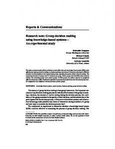
We consider the problem of developing accurate relative transforms between multiple aerial robots while operating in a common environment through shared laser sensor observations. As the system relies on a capacity constrained network, we focus on experimental questions relating computational complexity, shared data requirements, and team size. Toward studying this relationship, we propose a strategy that seeks to reduce data transfer and algorithmic complexity at the cost of reducing the accuracy of the computed relative transforms. We show the feasibility of the proposed technique experimentally and extend this discussion to larger teams where mild reductions in accuracy can permit real-time performance. Trials of sensory information (laser scans) are captured from fleets of quadrotors operating in three different environments (Fig. 1). These environments consist of a set of paths transitioning from a wide open room with clutter to a hallway environment (trial T1), a series of connected corridors and hallways (trial T2), and an outdoor hedge maze (trial T3). T1 Three robots navigating along a path from the same initial pose before diverging and traveling long distances in different directions. T2 Three robots navigating through hallways from different starting poses. All robots meet, and travel in the same direction around a 10×16 meter loop before diverging. T3 Three robots navigating an outdoor structured environment. Robots navigate low to the ground to capture laser scans of bushes and walls. Robots 2 and 3 have no trajectory overlap, but capture laser scans which share features. Pose estimates along the robot trajectories are generated through local instances of SLAM running on each quadrotor during operation. We use a laser and inertial based SLAM implementation similar to that of [14], which leverages ICP for laser odometry [15], a histogram filter for localization, and a UKF to fuse estimates [16]. Octomap is used for 3D mapping capabilities [17].
Experimental Study of Robust Multi-Robot Data Association
(a)
(b)
(c)
(d)
5
Fig. 1: (a): Quadrotor platform, equipped with an onboard computer (1.86 GHz Intel Core 2 Duo processor), IMU, laser, and beam deflector mirrors. Stereo cameras are not utilized in the described experiments. (b), (c), (d): Experiment environments for T1, T2, and T3.
3.2
Implementation
We pursue a centralized implementation where laser scan observations are distributed to and evaluated by a single vehicle (i.e., client-server model). Each new observation received by the server is matched against a history of all observations from other robots using a variant of ICP [18]. If there is a significantly low covariance in any one ICP match, a data association (ri , r j , k, l) ∈ F between the two robots, ri and r j , links the poses from which the matched scans were captured. After a specified number of observations are shared by all robots, transform hypotheses between pairs of robots are established using EM [12]. For each transform hypothesis generated this way, data associations formed between robot pairs which share similarity in translation and rotation are separated into a set of inliers. The transform hypothesis which contains the highest number of inlier data associations is chosen as the most probable transform. If the number of inliers is small for all transform hypotheses, none are selected, signifying that the robots are operating in disjoint environments. If a reliable transform has not yet been discovered, hypotheses are constantly generated and reassessed as new observations are shared between robots. 3.3
Computational Complexity and Saliency of Information
Given this implementation, we choose to evaluate three steps of the algorithm in an analysis of computational complexity (Table 1). SLAM is executed locally on each robot, and is therefore omitted. The server is responsible for managing all computations
6
E. Nelson, V. Indelman, N. Michael, F. Dellaert
in these three steps, and executes them in sequence when presented with new pose and sensor information from a robot. Step 1 Updates to a robot’s pose graph to incorporate a new pose and any new data associations formed with other robots since the previous update. Step 2 ICP and transform hypothesis generation between one robot’s history of shared scans and any new scans recently shared by other robots. Step 3 Sensor observation autocovariance calculation. Step 1 Edges are added to the multi-robot pose graph upon individual robot pose updates as well as multi-robot pose correspondences generated through data association. The pose graph is implemented with the GTSAM optimization library [19], which computes individual updates (nearly) linearly in the number of edges in the pose graph. Continuing the notation introduced in Sect. 2, the shared pose graph has E = R(|X r | − 1) + |F | edges if the poses of all robot are updated at a shared frequency. Since edges are added sequentially during run time, the total number of computations performed in Step 1 is roughly 12 (E 2 + E), resulting in a complexity of O(E 2 ). Step 2 To identify data associations from arbitrary local robot coordinate frames in a temporally invariant manner, every laser scan shared by one robot must be compared against each other robot’s history of laser scans. Assuming robot poses are updated with a shared frequency, every laser scan shared by an individual robot will be accompanied by R − 1 sensor observations shared by other robots. Growth in the laser scan histories of each robot results in a growth in the number of ICP comparisons performed between observations over time. Let each robot r gather a set of observations, Z r , and share a subset, Z¯ r ⊂ Z r , with other robots. Then the total number of ICP comparisons performed over the duration of the trial run time is |Z¯ r |
R(R − 1) ∑ i i=1
� � 1 = R2 − R |Z¯ r |2 + |Z¯ r | 2 This result implies that the run time complexity of Step 2 is O(R2 |Z¯ r |2 ). Step 3 The dominant source of complexity in Step 2 arises from R2 |Z¯ r |2 laser scan ICP comparisons from potentially large initial offsets over the duration of the run time, as well as EM on a number of transform hypotheses quadratic in |Z¯ r |. The algorithm can be made significantly more efficient through a reduction the number of observations in the
Table 1: Complexities of individual steps of the data association strategy. Algorithm Step Complexity
1 O
E2
2 �
O
R2 |Z¯ r |2
3 �
O (R|Z r |)
Experimental Study of Robust Multi-Robot Data Association
7
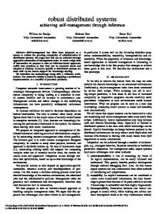
Fig. 2: Laser scan saliency along a robot’s trajectory with inlaid images of the environment. Magenta corresponds to high saliency, while teal corresponds to low saliency.
set Z¯ r as |Z¯ r | is not restricted to be equal to |X r |. We therefore propose a subsampling strategy that seeks to reduce |Z¯ r | based on laser scan autocovariance [20], which can be used as a scalar measure of laser scan saliency. Autocovariance is calculated by randomly perturbing the pose from which a laser scan was captured, performing ICP to match the perturbed scan against the original, and storing the resulting transformation mean and covariance. After N such iterations, autocovariance is computed by δ=
1 , trace (Σ )
where Σ is the covariance of the N-Gaussian mixture. To subsample, we skip nine of ten sequential laser scans and maintain at least 0.1 meters in normed (x, y) pose estimate between scans. Saliencies are calculated for the remaining set. Only scans with δ greater than a threshold, δs , are shared with other robots. Because laser scan saliency is only computed once per laser scan, the run time complexity of Step 3 is O(R|Z r |). Laser scan saliency is plotted along a robot trajectory from trial T2 in Fig. 2. 3.4
Network Complexity
Constrained network capacity is a concern when requiring the distribution of large amounts of shared data. Further, mesh networks exhibit a reduced capacity when distributing packets between multiple systems [21]. A conservative model of three robots sharing uncompressed scans (approximately 34 kB per scan) limits the data sharing rate of each robot to approximately 4 Hz. The rate reduces further with the number of robots where in practice an update rate of 1 Hz is expected for six vehicles [21].
8
E. Nelson, V. Indelman, N. Michael, F. Dellaert
35
−10 −12
25
−14 −16 Y (m)
15 Y (m)
30
Y (m)
20
20
10
−18 −20 −22
15
−24 −26
5
10
0 −25
−20
−15
−10 X (m)
−5
0
(a) r1 local frame (red)
5
5 −10
−28 −30 −5
0
5
10 X (m)
15
20
25
(b) r2 local frame (green)
30
−55
−50
−45 X (m)
−40
−35
−30
(c) r3 local frame (blue)
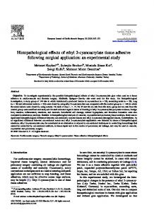
Fig. 3: Robot trajectories from T1 in a common frame after applying transforms resulting from data association. Estimates are expressed in the local frame of each robot. Inlier (black) and outlier (gray dashed) correspondences after a common reference frame has been established are shown.
4
Results and Discussion
The data association algorithm was used to calculate inter-robot relative transforms between robots in T1, T2, and T3. All reported transforms, Trri 1 , are expressed as a rotation followed by a translation from the local coordinate frame of robot ri to that of robot r1 . We first report on the accuracy of transforms calculated without saliency thresholding on laser scans. Trajectories, inlier data associations, and outlier data associations from T1 are shown in the local frame of each robot in Fig. 3. Robots begin from the same initial position and diverge after sharing a large number of laser scans in common. As such, strong hypotheses are formed in the initial stretch of the trajectory by the high number of inlier ICP correspondences. In the latter half of each robot’s trajectory, incorrect data associations are made between robots due to the similarity in laser features throughout the hallway environment. However, given the strength of the transform established in the initial poses, these data associations are considered outliers. Table 2 displays computed and measured transforms from all three datasets with no laser scan saliency thresholding. The transform with the largest error among all
Table 2: Computed and measured transformations Trr21 and Trr31 , with x, y in m and θ in rad. Trial T1 Trial T2 Trial T3 Transform Trr21 Trr31 Trr21 Trr31 Trr21 Trr31 x: -0.12 0.15 2.62 -4.53 1.41 -13.59 Computed y: -0.03 -0.27 7.45 -4.09 -3.99 -1.24 θ : -0.02 0.03 -1.57 0.00 0.97 2.05 x: 0.00 0.00 2.48 -4.60 1.42 -13.63 Measured y: 0.00 0.00 7.50 -3.99 -3.90 -1.02 θ : 0.00 0.00 -1.57 0.00 1.08 2.01
Experimental Study of Robust Multi-Robot Data Association
9
trials, Trr31 from T1, has a translation error norm of 0.31 meters. Rotational errors in all computed transforms are between zero and eight degrees. Figure 4(a) displays saliency plotted across trajectories in T2. Structural symmetries in the hallway environment cause ICP comparisons to converge to local minima during autocovariance computation, resulting in low saliency in areas such as four-way crossroads and corridors. The set of salient laser scans is roughly a subset of the set of shared scans that form high numbers of ICP correspondences with other robots (Fig. 4(b)). This inclusion signifies that autocovariance is a suitable metric for laser scan subsampling.
r1
r2
r3
5
x 10
15
15
10
10
10
5
y (m)
15
y (m)
y (m)
8
5
5
4
0
0
0
−5
−5
−5
−10
−5
0
5
10
−10
x (m)
−5
0
5
6
10
−10
2
−5
0
x (m)
5
0
10
x (m)
(a) r 2 shared with r 1
r 3 shared with r 1 15
10
10
10
5 0 −5
y (m)
15
y (m)
y (m)
r 1 shared with r 2 15
5 0 −5
11 10 9
5 0
8
−5
7 0
10
−10
0
10
−10
0
10
x (m)
x (m)
x (m)
r 1 shared with r 3
r 2 shared with r 3
r 3 shared with r 2
15
15
10
10
10
5 0 −5
y (m)
15
y (m)
y (m)
−10
5 0 −5
6 5 4 3
5 0
2
−5
1 −10
0
x (m)
10
−10
0
x (m)
10
−10
0
10
x (m)
(b) Fig. 4: 4(a) Saliency, δ , of shared scans in T2. 4(b) Number of ICP scan correspondences found between robot pairs in T2, plotted along robot trajectories. Counts mark the number of ICP correspondences made between the scan shared from the marked pose with all scans shared by the other robot.
10
E. Nelson, V. Indelman, N. Michael, F. Dellaert
Table 3: Computed and measured transforms before and after saliency thresholding, with kx, yk in m and θ in rad. ∼ signifies that a transform was not established. Data set D2 Data set D3 δs Shared scans Trr21 error Trr31 error Shared scans Trr21 error Trr31 error r1 r2 r3 kx, yk θ kx, yk θ r1 r2 r3 kx, yk θ kx, yk θ 0 75 77 65 0.15 0.00 0.20 0.00 74 55 71 0.09 0.10 0.22 0.05 2×10⁵ 22 26 23 0.19 0.00 0.24 0.00 26 18 36 0.22 0.08 0.59 0.13 4×10⁵ 22 24 23 0.19 0.00 0.24 0.00 24 16 35 ∼ ∼ 0.59 0.13 6×10⁵ 16 18 19 0.18 0.01 0.29 0.02 22 15 31 ∼ ∼ 0.67 0.13 8×10⁵ 8 6 4 ∼ ∼ ∼ ∼ 8 1 15 ∼ ∼ ∼ ∼
Transform accuracies for T2 and T3 are shown in Table 3 with varying saliency thresholds, δs . Thresholding with δs = 2 × 10⁵ reduces the average number of scans used to 36 percent of the total. By increasing the saliency threshold to δs = 4 × 10⁵ , there are no longer enough inlier ICP correspondences between robots r1 and r2 from T2 to compute a transform. While thresholding scans by their saliency increases error in both translation and rotation, this inscrease, at worst, raises normed (x, y) error by 0.37 meters, and rotation error by 0.08 radians over a trajectory roughly 20 meters in length. At δs = 8 × 10⁵ , no robot pairs have enough inlier correspondences to form a transform.
15
10
5
y (m)
y (m)
10
r1
5
r2, δs = 0
0 r1
r2, δs = 2× 10⁵
0
r3, δs = 0
−5 5
r3, δs = 2× 10
r2, δs = 0 r2, δs = 2× 10⁵ r3, δs = 0
−5
−10 −10
−5
0
x (m)
(a)
5
10
−10
r3, δs = 2× 10⁵
−5
0
5
10
15
x (m)
(b)
Fig. 5: (a), (b): Robot trajectories from T2 and T3 in the frame of r1 after applying transforms resulting from the data association strategy with and without saliency thresholding. Saliency thresholding makes little difference to transform estimates. Laser scans from r1 are shown.
Experimental Study of Robust Multi-Robot Data Association
11
Table 4: Trial durations, number of shared scans, and mean and maximum sharing frequencies for δs = 0 and δs = 2 × 10⁵ . Robot Duration (s) T2: r1 37.4 T2: r2 39.0 T2: r3 32.5 T3: r1 35.5 T3: r2 27.6 T3: r3 37.4
|Z r | 75 77 65 71 55 74
δs = 0 δs = 2 × 10⁵ r Max (Hz) Mean (Hz) |Z | Max (Hz) Mean (Hz) 2.08 2.00 22 1.01 0.59 2.02 1.97 26 1.28 0.67 2.02 2.00 23 0.95 0.71 2.06 2.00 26 0.98 0.73 1.99 1.99 18 1.31 0.65 1.98 1.98 36 1.20 0.96
Trajectories from T2 and T3 are shown in Fig. 5 with and without salient scans thresholded at δs = 2 × 10⁵ . Thresholding laser scans from robots in T2 by saliency leads to a 0.04 meter increase in translation error for both robots, with no difference in rotation error. In trial T3, thresholding increases translation error by 0.13 and 0.37 meters, and rotation error by −0.02 and 0.08 radians for Trr21 and Trr31 , respectively. Without saliency thresholding, the total number of shared scans in all trials remains below the data sharing limit of 4 Hz described in Sect. 3.4 for three robots (Table 4). During trials, laser scans were captured on each robot at 20 Hz and uniformly subsampled to one tenth of the original amount. Mean sharing frequency across all robots with no laser scan subsampling remains within a small margin of 2 Hz, implying no robots were limited by the 0.1 meter distance constraint between sequential laser scans. After thresholding shared scans by saliency with δs = 2 × 10⁵ , the mean sharing frequency decreases to below 1 Hz for all robots. The maximum sharing frequencies for both values of δs permit unconstrained data transfer on a mesh network with three robots. With a mesh network of six robots, the maximum sharing frequencies indicate that durations of increased sharing would exceed the network transfer limit of 1 Hz per robot by up to 208 percent for δs = 0 and up to 131 percent for δs = 2 × 10⁵ . Figure 6 shows the proportion of the process run time consumed by each step of the data association algorithm with δs = {0, 2, 4, 6} × 105 for trials T2 and T3. After subsampling scans with δs = 2 × 10⁵ , Step 3 (autocovariance calculations for all laser scans) increases from 21.5 percent of the total computation time (averaged across both trials) to 46.3 percent. Because total time devoted to Step 3 is not a function of δs , thresholding on saliency by δs = 2 × 10⁵ decreases the total run time of the algorithm by 46.4 percent. Note that due to the quadratic complexity of Step 2, this estimate is only reflective of trajectories of the same length as those in T2 and T3.
5
Conclusion
In this work we investigated the problem of computing relative transformations between multiple vehicles from shared sensor observation correspondences. Experiments were developed to evaluate the accuracy, computational complexity, and network complexity
12
E. Nelson, V. Indelman, N. Michael, F. Dellaert
1 Step 1 Step 2 Step 3
0.8 0.6 0.4 0.2 0
δs = 0
δs = 2 × 10 5
δs = 4 × 10 5
δs = 6 × 10 5
(a) 1 Step 1 Step 2 Step 3
0.8 0.6 0.4 0.2 0
δs = 0
δs = 2 × 10 5
δs = 4 × 10 5
δs = 6 × 10 5
(b) Fig. 6: Proportion of total run time consumed by each step of the algorithm for (a) trial T2, and (b) trial T3 with varying values of δs . Time consumed by Step 3 is constant across values of δs , signifying that as δs increases the total run time of the algorithm decreases.
of a data association strategy introduced by Indelman, et al. [12]. A sensory observation subsampling strategy based on laser scan autocovariance was introduced to reduce the number of laser scans shared between robots, therefore reducing the both the computational complexity of the algorithm as well as the rate of data sharing between robots. Multi-robot trials were collected onboard quadrotors operating throughout three dissimilar environments. The trials were used to evaluate the accuracy of the data association algorithm in different domains of operation. We showed that by intelligently selecting which laser scans to share over the network, the total run time of the algorithm could be reduced by over 46.4% for three-robot trajectories on the order of 20 meters in length. In addition, we demonstrated that the accuracy of transforms resulting from the algorithm does not suffer significantly from subsampling laser scans based on their autocovariance. Finally, we experimentally evaluated data sharing rates to show that this approach can be implemented using a mesh network for at least three robots.
Experimental Study of Robust Multi-Robot Data Association
13
References 1. Fenwick, J.W., Newman, P.M., Leonard, J.J.: Cooperative concurrent mapping and localization. In: Proc. of the IEEE Intl. Conf. on Robot. and Autom., Washington, DC (May 2002) 1810–1817 2. Bailey, T., Bryson, M., Hua, M., Vial, J., McCalman, L., Durrant-Whyte, H.: Decentralised cooperative localisation for heterogeneous teams of mobile robots. In: Proc. of the IEEE Intl. Conf. on Robot. and Autom., Shanghai, China (May 2011) 2859–2865 3. Montijano, E., Aragues, R., Sagues, C.: Distributed data association in robotic networks with cameras and limited communications. IEEE Trans. Robot. 29(6) (December 2013) 1408–1423 4. Olson, E., Leonard, J., Teller, S.: Robust range-only beacon localization. In: IEEE Auton. Underwater Vehicles, Sebasco, Maine (July 2004) 66–75 5. Howard, A., Parker, L.E., Sukhatme, G.S.: Experiments with a large heterogeneous mobile robot team: Exploration, mapping, deployment and detection. Intl. J. Robot. Research 25(56) (May 2006) 431–447 6. Zhou, X.S., Roumeliotis, S.I.: Multi-robot SLAM with unknown initial correspondence: The robot rendezvous case. In: Proc. of the IEEE/RSJ Intl. Conf. on Intell. Robots and Syst., Beijing, China (October 2006) 1785–1792 7. Charrow, B., Michael, N., Kumar, V.: Cooperative multi-robot estimation and control for radio source localization. In: Proc. of the Intl. Sym. on Exp. Robot., Quebec City, Canada (June 2012) 8. Thrun, S., Thayer, S., Whittaker, W., Baker, C., Burgard, W., Ferguson, D., Hahnel, D., Montemerlo, M., Morris, A., Omohundro, Z., Reverte, C., Whittaker, W.: Autonomous exploration and mapping of abandoned mines. IEEE Robot. Autom. Mag. 11(1) (December 2004) 79–91 9. Michael, N., Shen, S., Mohta, K., Mulgaonkar, Y., Kumar, V., Nagatani, K., Okada, Y., Kiribayashi, S., Otake, K., Yoshida, K., Ohno, K., Takeuchi, E., Tadokoro, S.: Collaborative mapping of an earthquake-damaged building via ground and aerial robots. J. Field Robot. 29(5) (September 2012) 832–841 10. Cunningham, A., Wurm, K.M., Burgard, W., Dellaert, F.: Fully distributed scalable smoothing and mapping with robust multi-robot data association. In: Proc. of the IEEE Intl. Conf. on Robot. and Autom., Saint Paul, MN (May 2012) 1093–1100 11. Montijano, E., Martinez, S., Sagues, C.: Distributed robust data fusion based on dynamic voting. In: Proc. of the IEEE Intl. Conf. on Robot. and Autom., Shanghai, China (May 2011) 5893–5898 12. Indelman, V., Keyes, D., Nelson, E., Michael, N., Dellaert, F.: Multi-robot pose graph localization and data association from unknown initial relative poses via expectation maximization. In: Proc. of the IEEE Intl. Conf. on Robot. and Autom., Hong Kong, China (May 2014) To Appear. 13. Lu, F., Milios, E.: Robot pose estimation in unknown environments by matching 2D range scans. J. Intell. Robotic Syst. 18(3) (March 1997) 249–275 14. Shen, S., Michael, N., Kumar, V.: Autonomous multi-floor indoor navigation with a computationally constrained MAV. In: Proc. of the IEEE Intl. Conf. on Robot. and Autom., Shanghai, China (May 2011) 20–25 15. Pomerleau, F., Colas, F., Siegwart, R., Magnenat, S.: Comparing icp variants on real-world data sets. Auton. Robots 34(3) (April 2013) 133–148 16. Thrun, S., Burgard, W., Fox, D.: Probabilistic Robotics. The MIT Press, Cambridge, MA (2005)
14
E. Nelson, V. Indelman, N. Michael, F. Dellaert
17. Hornung, A., Wurm, K.M., Bennewitz, M., Stachniss, C., Burgard, W.: OctoMap: An efficient probabilistic 3D mapping framework based on octrees. Auton. Robots 34(3) (April 2013) 189–206 18. Censi, A.: An accurate closed-form estimate of icp’s covariance. In: Proc. of the IEEE Intl. Conf. on Robot. and Autom., IEEE (2007) 3167–3172 19. Dellaert, F.: Factor graphs and gtsam: A hands-on introduction. Technical Report GT-RIMCP&R-2012-002 (2012) 20. Nieto, J., Bailey, T., Nebot, E.: Recursive scan-matching slam. Robotics and Autonomous Systems 55(1) (2007) 39–49 21. Jun, J., Sichitiu, M.L.: The nominal capacity of wireless mesh networks. Wireless Communications, IEEE 10(5) (2003) 8–14