MBT 2006
An Extension of the Classification-Tree Method for Embedded Systems for the Description of Events Mirko Conrad 1 DaimlerChrysler AG, Alt-Moabit 96a, D-10559 Berlin, Germany
Alexander Krupp 2 Paderborn University / C-LAB, Fuerstenallee 11, D-33102 Paderborn, Germany
Abstract Nowadays, model-based test approaches are indispensable for the quality assurance of invehicle control software. In practice, the Classification-Tree Method for Embedded Systems (CTMEMB ) is used to realize a compact graphical representation of test scenarios. Up to now, the CTMEMB has been used mainly in the area of continuous systems. Though the depiction of events within test scenarios is possible already by using existing means of description, there is still room for improvements. Thus, we will introduce in the following a novel extension of the Classification-Tree Method for Embedded Systems for a compact, natural depiction of event-like behaviour which we will illustrate by means of several examples from the area of in-vehicle control software. Key words: classification-tree method, CTMEMB , embedded systems, test scenario description, events
1
Introduction
The selection of suitable, i.e. error-sensitive, test scenarios is the most crucial activity for a trustworthy test of in-vehicle software[3]. It finally determines the scope and quality of the test. Moreover, an appropriate description of the test scenarios used is essential for the human tester. Based on the data-oriented partitioning of the input domain of the system under test, the Classification-Tree Method for Embedded Systems CTMEMB [4,5,6] facilitates a systematic design of time-variable test scenarios and their graphical description. CTMEMB provides a compact, problemoriented graphical representation, which is suitable for a human tester, containing a 1 2
Email:
[email protected] Email:
[email protected] This paper is electronically published in Electronic Notes in Theoretical Computer Science URL: www.elsevier.nl/locate/entcs
Conrad, Krupp
high potential for understandability and reusability. The CTMEMB has recently been successfully employed in different control software development projects[12]. One of the main application areas is the testing of in-vehicle software developed in a model-based way[1,2,15]. Strengths of the CTMEMB approach are the description of time-continuous test patterns. However, parts of modern automotive control systems are event-based. So, events have to be a natural part of test descriptions for mixed discrete-continuous systems. The current CTMEMB notation is already capable of the description of event-like test scenarios, but the resulting descriptions are unnecessary complex. Therefore, a novel extension of the Classification-Tree Method for Embedded Systems facilitating a compact description of events will be proposed in the remainder of the paper. Section 2 summarizes main concepts and the notation of the CTMEMB . Section 3 describes the proposed extension for event description. Section 4 illustrates its application by means of three different examples. Section 5 relates to other work and section 6 concludes the paper.
2
The Classification-Tree Method for Embedded Systems
Classification Trees were introduced during the early 90s by Grimm and Grochtmann for the structured representation of test cases [9,10]. The construction of classification trees and their associated combination tables is supported by the Classification-Tree Method (CTM), which is derived from the category-partition method[13]. In its basic form, a classification tree and the accompanying combination table describe abstract high-level test cases in a graphical manner without an explicit notion of time. Initially, the input domain of the system under test (SUT) is partioned separately under various aspects relevant to the test. This is visually represented by means of a classification tree. Then, the resulting partitions are recombined within the combination table in order to form test cases. Since 1999, the method and notion has been enhanced by Conrad and Fey to accommodate the description of time-dependent test scenarios termed test sequences[4,5,6,7]. These extensions are known as the Classification-Tree Method for Embedded Systems CTMEMB (previously known as CTM/ES). In CTMEMB , the classification tree is derived directly from the technical interface of the system under test, i.e. each input of the SUT is represented as a classification in the tree. Each input domain is partitioned into intervals or single values represented as classes below the accompanying classification. Abstract test sequences can be described by means of the classifications and classes constructed in this manner. These sequences consist of separate test steps, whose chronology is shown in the rows of the combination table beneath the tree. Each row represents a test step, where each input in the classification tree is restricted to one of its classes via a marking in the combination table. The activation time of each test step is noted in a separate column of the combination table as Time Tag. 2
Conrad, Krupp marking
description
meaning
l
“full circular”
select any value from class range
m
“empty circular ”
return to / repeat last value from class (history dependent marking)
n
“quadratic”
fire event
Table 1 Marking types
The input values between synchronization points are calculated by means of interpolation. The interpolation function can be chosen from different function types, e.g., step, ramp and sine functions. An interpolation function is represented in the combination table by a certain line style between two subsequent markings. Technically, the classifications of the classification tree describe an abstract state space with domain Xi for a classification i (fig 1, left). Each classification represents an input variable of the SUT. The test scenario is described in the time domain by means of synchronization points. If T = {t0 , t1 , ..., te } with t0 < t1 < ... < te describes the set of synchronization points, then the time intervals [t0 , t1 ], [t1 , t2 ], ..., [te−1 , te ] are called test steps. A class function π˜ i : T → Pi (Xi ) assigns to each synchronization point a partition (i.e. a class) of Xi . It is described by means of the combination table. A value function vi : T → Xi assigns a value to each synchronization point of a classification i. vi is called compatible if for all times t ∈ T holds, that πi (vi (t)) ∈ π˜ i , with the standard projection πi : Xi → Pi (Xi ). An interpolation function ii : T → I assigns an interpolation rule with I = {step, ramp, sine} to an input i for every synchronization point in T . An interpolation rule ii,tk (t) : [tk , tk+1 ] → Xi provides the value of an input beginning at synchronization point tk through the interval [tk , tk+1 ]. When, e.g., a ramp or a sine is applied as interpolation rule with a compatible value function, the result is a continuous test-data waveform (time series) v¯ i : T¯ → Xi , where T¯ ⊃ T is a strictly ordered set of times according to the classical notion of time (cf. [5]).
3
A Description of the Extensions
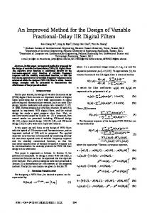
In order to describe an input event i with the possible i1 , i2 , . . . , ik values (or, alternatively, k exclusive events which are related) a classification i is created in the classification tree, containing the classes i1 , i2 , . . . , ik and ide f ault for the default value, which means ‘event is NOT available’, essentially. The temporal sequence of events as well as the design of time-variable signal forms is described in the combination table beneath the classification tree. For this, an additional quadratic marking type is introduced. An overview and short description of the available marking types is displayed in table 1. If the appearance of an event ik needs to be described at the point of time ti in the combination table a corresponding row with the time tag ti is inserted into the table. This row is marked with the new quadratic marking type underneath the 3
Conrad, Krupp
i i2 i1 idefault
t0 t1 t2 ...
Inputs
Inputs
i
i
idefault i1 i2 ... 1.1 1.2: event 1 1.3 1.4: event 2 1.5: ... 1.n:
t
idefault i1 i2 ...
Time [s] t0 t1 t1+∆t t2 t2+∆t
1.1 1.2: event 1 1.3: event 2 ... 1.n:
Time [s] t0 t1 t2 tend
tend
Figure 1. Modeling of Events: previous and proposed notation
class ik . For the beginning and the end of the test sequence there are usually two more rows needed at the beginning and the end of the combination table, which are marked underneath the default class ide f ault with one of the circular standard markings (fig. 1, right-hand side). The full circular marking means that a specific value is chosen arbitrarily from the associated class, whereas an empty circular marking means the same value is to be selected, which was selected the last time the associated class was used. The meaning of the circular standard markings remains unchanged compared to the familiar form of CTMEMB (see [4]). A marking of a class ik at the point of time ti with the quadratic marking type means that at this point in time an event i with property k fires. After the point in time ti the default value ide f ault is assumed, until another quadratic marking is encountered at some synchronization point t j . The proposed extension of the classification-tree method for embedded systems by event markings allows a decidedly more compact description of events or similar issues when compared to already existing methods of description. Up to now, two rows labeled with the time tags ti and ti+∆t were needed to describe an event ik at the time ti in the combination table 3 . The first of the two rows describes the appearance of the new value ik while the second row describes its retraction in the next possible time step (Fig. 1, left). The introduction of event markings can thus reduce the amount of rows in the combination table by up to 50%. The results are significantly more compact and thus more readable combination tables. Fig. 1 juxtaposes the present (left) and the new, more compact method of description with 3
∆t here denotes the cycle time of the contemplated system.
4
Conrad, Krupp
event markings (right) using a generic example. The proposed extension proves to be beneficial particularly for simultaneous descriptions of events and time-continuous signal forms within a classification tree. Where an equivalence class of the CTMEMB represents a value or a value interval, an event equivalence class usually represents a specific message or a class of messages to be sent. The underlying test-bench is notified as soon as the message event is triggered. Based on the notion of test sequence and interpolation rule in CTMEMB [5] we describe an expanded notion which allows the introduction of events at precise moments in time. CTMEMB describes the derivation of continuous test-sequences by means of variables and by test-steps which are connected by interpolation rules. An event-variable is a variable xi with (finite and enumerable) domain Xi . For an event-variable, we define a modified interpolation rule as follows. Let {t0 , t1 } be a set of (two) consecutive synchronization points with t0 ≤ t1 and with associated values x0 , x1 ∈ X. ∆t is called sampling time. Its multiples are k∆t, k ∈ N0 . Then a function j : X {t0 ,t1 } × k → X associates a value from X with each discrete point in time k∆t within and including the boundaries {t0 , t1 }. We call j the discrete interpolation rule. One example of a discrete interpolation rule is: x0 , k = 0 jimpulse (k) : 0 , otherwise jimpulse facilitates the introduction of a cycle-accurate singular impulse into the discretized test data waveform such that the first sample of the synchronization interval at 0 · ∆t is of value x0 and all following samples are of value 0. This function also provides a discretization rule for signals described by way of DiracDistributions as shown in [11] for signal derivations. For message-sending events the discrete interpolation rule is as follows: x0 , k = 0 jevent (k) : null , otherwise x0 ∈ X, X = {(ide f ault ≡ null), i1 , i2 , . . .} ⊂ (STRING ∪ null) where X is the input domain which encompasses a set of strings and a neutral element null which represents the case that no message is queued for the respective input. Note that the application of jevent on an input signal must not be mixed with other interpolation rules on the same signal which would cover an input domain other than strings and null.
4
Application Examples
The following subsections explain the event extension of the CTMEMB by means of two examples. The first example is a 4-way cruise control lever and the second 5
Conrad, Krupp
Figure 2. Cruise Control Lever Positions
example explains the temporal modeling of CAN bus messages. 4.1
Event Groups
The modeling of event groups can be explained by considering the modeling of a cruise control lever. Normally the control lever of an adaptive cruise control system is positioned in the middle. Short-term moving (tapping) of the lever in one of the four directions activates one of the functions Accelerate (Set+), Decelerate (Set-), Resume and Off (see Fig 2). Immediately after tapping, the lever automatically returns to the normal position. These events can not occur simultaneously for reasons of design. Using the above-mentioned expansion of the CTMEMB describing events, the position of the cruise control lever can be described through the classification LeverPos (compare Fig. 3). Class 0 corresponds to the default position, classes 1 to 4 to the four events alternatively possible. In such a way, usage scenarios or test patterns for an adaptive cruise control system can compactly be described. Besides containing control lever events, these usage scenarios also include continuous input signal forms for the other input signals such as the two pedal positions phi_Acc and phi_Brake. Fig. 3 depicts such a test pattern for cruise controls which was automatically generated with the aid of the EST (Evolutionary Safety Testing) approach. The depicted test pattern was derived from [14]; the temporal sequence of the control lever event is depicted on the top left. The combination table would roughly be double its size without the expansions of event depiction. Furthermore, the ramp-shaped input signal segments of v_tar would have to be split up in two ramp segments respectively, requiring additional (auxiliary) classes belonging to v_tar. 4.2
CAN Messages
The proposed extension is additionally well-suited for the description of bus communications between electronic control units. As an example, the transmission behavior of two control units of a CAN bus (cf. [8]), which can send the CAN messages a, b, c or x and y., is described in Fig. 4. The two control units show independent transmission behavior; therefore each control unit is modeled by an individual event group, a classification, to which the CAN identifiers possible and 6
Conrad, Krupp
Inputs
phi_Acc
phi_Brake
0 100
0
100
1: violation of safe dist…
LeverPos
0 1 2 3 4
v_tar
20 21 24 25 27 40 Time [s]
1.1: init
0
1.2: start tseq
10.0000
1.3:
13.9130
1.4:
20.4348
1.5:
25.6522
1.6:
38.6957
1.7:
40.000
1.8:
41.3043
1.9:
53.0435
1.10:
59.5652
1.11: stop tseq
70.0000
Figure 3. Modeling of a Test Pattern for an Adaptive Cruise Control System with Event Group and Continuous Signal waveforms
‘no msg’ (for the default value) are assigned to as classes. This way, it is possible to easily depict both the concurrent transmission attempt of the two control units (time tags t1 and t4 in Fig. 4) and the exclusive transmission of one control unit (time tags t2 and t3 in Fig. 4). A combination of the above presented description of the transmission behavior of the control units with the mechanisms proposed in the original CTMEMB for the depiction of expected behavior on classification tree level (cf. [5]) allows a test description of complex CAN networks.
5
Related Work
An approach for improving the test coverage of Simulink models by means of the classification-tree method for embedded systems was introduced in [11]. An input is described by the actual signal form as well as by its derivation. The derivation waveform of the signals is described via Dirac impulses, which can be understood as an instantiation of the general approach for the event description presented in this paper. 7
Conrad, Krupp msg c ECU #1 msg b msg a t0 t1 t2
t4
msg y ECU #2 msg x t0 t1
t3 t4
t
Inputs
t
ECU #1
ECU #2
no msg msg a msg b msg c no msg msg x msg y Time [s] t0 1.1 t1 1.2: event 1 t2 1.3: event 2 t3 1.4: event 3 t4 1.5: event 4 tend 1.n:
Figure 4. Modeling CAN Bus Signals
6
Summary
This paper presented an extension to the Classification-Tree Method for Embedded Systems (CTMEMB ) for the compact description of events within test scenarios for mixed discrete / continuous systems. For the depiction of event-like issues a new square marking type is being used, which corresponds to the additional transition function with event semantics. The proposed notational extensions of the CTMEMB allow very compact and natural descriptions of events especially within test or usage scenarios where continuous and event-based inputs are to be combined. In comparison with the previously used approaches, the size of the combination tables can be reduced by up to 50%. Thanks to the open structure of the original CTMEMB framework, it is possible to integrate the extensions seamlessly into present syntax and semantics. The extension of the Classification-Tree Method for Embedded Systems presented in this paper allows access to new fields of application for the compact depiction of test scenarios by means of the CTMEMB . Among them are, for example, event-based body control systems and ECU clusters connected via CAN. The implementation of the introduced extensions for the CTMEMB in the test tools supported is possible in a straightforward manner.
Acknowledgements The work described was partially performed within the IMMOS project funded by the German Federal Ministry of Education and Research (www.immos-project.de). The authors wish to thank Wolfgang Mueller (C-LAB) and Ines Fey (DaimlerChrysler) for helpful discussions. 8
Conrad, Krupp
References [1] Aldrich, W., Using Model Coverage Analysis to Improve the Controls Development Process, in: AIAA Modeling and Simulation Conference, Monterey, California, 2002. [2] Angermann, A., M. Beuschel, M. Rau and U. Wohlfahrth, “Matlab – Simulink – Stateflow: Grundlagen, Toolboxen, Beispiele,” Oldenbourg Verlag, München, 2004. [3] Broekman, E. and E. Notenboom, “Testing Embedded Software,” Addison-Wesley, London(GB), 2003. [4] Conrad, M., A Systematic Approach to Testing Automotive Control Software, in: Proc. 30. Int. Congress on Transportation Electronics (Convergence ’04), Detroit, MI, USA, 2004, pp. 297–308, sAE Techn. Paper #2004-21-0039. [5] Conrad, M., “Modell-basierter Test eingebetteter Software im Automobil (Modelbased Testing of Embedded Automotive Software),” PhD Thesis, Deutscher Universitäts-Verlag, Wiesbaden, 2004. [6] Conrad, M., The Classification-Tree Method for Embedded Systems, in: Dagstuhl Seminar Proceedings 04371, 2005. [7] Conrad, M., H. Dörr, I. Fey and A. Yap, Model-based Generation and Structured Representation of Test Scenarios, in: Workshop on Software-Embedded Systems Testing (WSEST), Gaithersburg, USA, 1999. [8] Etschberger, K., editor, “CAN Controller-Area-Network,” Fachbuchverlag Leipzig, 2002. [9] Grimm, K., “Systematisches Testen von Software - Eine neue Methode und eine effektive Teststrategie (Systematic Software Testing – A new method and an effective test strategy),” Number 251 in GMD-Report, GMD, Oldenbourg, 1995. [10] Grochtmann, M. and K. Grimm, Classification Trees for Partition Testing, Software Testing, Verification and Reliability 3(2), 1993, pp. 63–82. [11] Krupp, A. and W. Mueller, Die Klassifikationsbaummethode für eingebettete Systeme mit Testmustern für nichtkontinuierliche Reglerelemente, in: INFORMATIK 2005 – Informatik LIVE!, Bd. 2, 35. GI-Jahrestagung, 3. ASWE Workshop, GI, Bonn, 2005. [12] Lamberg, K., M. Beine, M. Eschmann, R. Otterbach, M. Conrad and I. Fey, Modelbased Testing of Embedded Automotive Software using MTest, SAE 2004 Transactions, Journal of Passenger Cars - Electronic and Electrical Systems 7 (2005), pp. 132–140. [13] Ostrand, T. J. and M. J. Balcer, The Category-Partition Method for Specifying and Generating Functional Tests, Commun. ACM 31(6), 1988 pp. 676–686. [14] Pohlheim, H., M. Conrad and A. Griep, Evolutionary Safety Testing of Embedded Control Software by Automatically Generating Compact Test Data Sequences, SAE 2005 Transactions, Journal of Passenger Cars - Mechanical Systems (2005), pp. 804– 814. [15] Rau, A., “Model-Based Development of Embedded Automotive Control Systems,” Ph.D. thesis, Dept. of Computer Science, University of Tübingen, Germany (2002).
9