An Extension of Problem Frame Notation for Software Product Lines Hailang Zuo, Mike Mannion, David Sellier, Richard Foley School of Computing and Mathematical Sciences Glasgow Caledonian University 70 Cowcaddens Road Glasgow G4 0BA Scotland, United Kingdom E-mail:
[email protected]
Abstract A software product-line is a set of software– intensive systems sharing a common set of managed requirements. A technique for requirements analysis of single systems, but rarely applied to product lines, is Problem Frames. Problem Frame theory omits support for the management and exploitation of product line requirements variability. This paper presents some notation to support requirements and machine variability in problem frames. It also describes some transitioning rules between requirements and machines that can help to manage product line evolution. We illustrate our ideas using a mobile phone worked example.
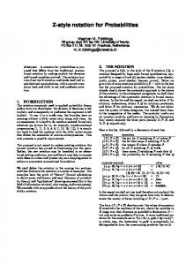
A technique for the requirements analysis of single systems, but which has rarely been applied to product lines is Problem Frames [2, 3]. Figure 1 shows that a problem frame consists of a problem domain that describes the subset of the real world that is of concern, a requirement that describes what we wish to be true of phenomena in the problem domain, and a machine that describes the behaviour that must be exhibited by an information system to bring about the requirement. The connection from the problem domain to the machine is represented by shared phenomena, “a” and “b”. Shared phenomena can be data, events, commands and states. The solution design task is to build the machine. Machine
a
Problem Domain
b
Requirement
1. Introduction The business of many organizations is to develop a product line of artefacts or services e.g. mobile phones, washing-machines, financial product. These products are often software intensive and their evolution often necessitates a corresponding change to the software that underpins those products. (Software) Product-Line Engineering is the discipline of engineering a set of (software-intensive) systems sharing a common, managed set of features that satisfy the specific needs of a particular market segment or mission, by developing them from a common set of core assets in a prescribed way [1]. As a product-line evolves and the variability inherent in the common set of core assets becomes more complex, a constant challenge in the drive to maximise profits is to find a compromise between satisfying customers’ changing needs and minimising the cost of changing these assets.
Proceedings of the 12th Asia-Pacific Software Engineering Conference (APSEC’05) 0-7695-2465-6/05 $20.00 © 2005
IEEE
Figure 1 Element of Problem Frame An advantage of problem frames is the emphasis placed on problem understanding and description so that they complement many structured and objectoriented analysis methods that arguably give more attention to solution design. A detailed treatment of the application of problem frames is presented in [4]. A motivation for problem frames was to provide a problem analysis toolkit for requirements engineers that recognised that there are classes of problem and that a class of problem has a solution type. However, the toolkit omitted to provide notational and process support to model the constraints placed upon problem analysis by existing solutions. Some extensions to the theory have been proposed to address this weakness. Projection domains [5, 6] can help to model machine-
to-machine interfaces in distributed systems. Machine notation can be extended [7] by annotations that show existing architectural services that can be factored into subsequent machine specifications. New products can be developed by selecting desired requirements from a set of product line requirements. Critical to this approach is the management of the requirements’ variability between products and its impact on selection methods. An added complication in practice is that selection is constrained by the existing product line architecture. Generally, such constraints are influential because they represent a substantial investment of resources. We presented an approach to address this problem by examining the concept of a feature [8], as a distinguishing characteristic of a software item i.e. located in the solution domain, and defining some transitioning rules that map the selection constraint values of requirements to the selection constraint values of features [9]. In this paper we introduce some additional notation for problem frames for product line problems and describe some transitioning rules between requirements and machines that can help understand and manage variability. We illustrate our ideas using a worked example of a simplified mobile phone. The paper is organized as follows. Section 2 defines variability types of requirements and machines presents an extension of problem frames to manage variability. Section 3 discusses the selection constraints and mapping rules. Section 4 presents a worked example of a mobile phone. Section 5 discusses the advantages and constraints of the idea. Section 6 makes a conclusion.
product lines. A requirement r can have a reuse property rRP. A machine m can have a reuse property mRP. RP
Machine
Figure 2 shows an extension of the problem frames notation, which supports the concept of variability in
Proceedings of the 12th Asia-Pacific Software Engineering Conference (APSEC’05) 0-7695-2465-6/05 $20.00 © 2005
IEEE
Domain
b
Requirement
RP: Reuse property; RM: Related Machine; RR: Name of Related Requirements;
Figure 2 Extension of Problem Frames Notation
2.1 Reuse Properties of Requirements One reuse property of a requirement can be a selection type to indicate whether the requirement should be realized in a specific product. A reuse property of a requirement can have one of 4 values. 1.
mandatory: a mandatory requirement is always part of a product in a product-line if its parent requirement is part of the product-line. For example, in a mobile phone product-line, a parent requirement can be “The mobile phone shall have the digital camera.” Its mandatory child requirement can be “The mobile phone can take a photograph.” If a parent requirement is selected as a part of a product-line, the child requirement is a part of the product-line.
2.
(variable) multiple adaptor: multiple adaptor requirements are connected via a list of alternative relationships, i.e. one or more than one requirement out of a set of requirements with the same parent can be chosen to be in the system if the set’s parent requirement is part of the system. For example, a parent requirement can be “The mobile phone shall have the ability to make a call” and its alternative child requirements can be “A call can be made by dialling numeric digits”, “A call can be made by selecting a number from a phone book” and “A call can be made by calling back from a call log.”
3.
(variable) optional: an optional requirement may or may not be part of a system. For example, in a mobile phone product-line, the requirement to have an email facility might be optional.
4.
(variable) single adaptor: adaptor requirements are connected via an exclusive OR relationship, i.e. exactly one requirement out of a set of requirements with the same parent can be chosen to be in the system if the set’s parent requirement is part of the system. For example, in a mobile phone product-line, a parent requirement can be “The mobile phone shall have a Display” and its
2. Software Product-Line Requirements and Machines At the heart of product line engineering lies the challenge of leveraging greater reuse by separating commonality and variability. Variability can follow three patterns [13]: optional, single (xor specialization) or multiple parallel (or specialization) variants. Applied to requirements selection, an optional variant means a requirement can be selected or not, a single variant means choosing a single requirement from a set of n requirements, and a multiple variant means choosing m requirements from n. Variant types can also be combined.
RP
a
mutually exclusive child requirements can be “The mobile phone has a Black & White Display.” and “The mobile phone has a Colour Display”.
2.2 Reuse Properties of Machines
(a) Mandatory
Mandatory
Machine
Domain
Requirement
(b) Variable
Requirement
A reuse property of a machine can be a selection reason to decide which machine shall be selected as a part of a solution for a specific product. Each machine in a software product-line can have one of 4 values. mandatory: a mandatory machine is always part of a product in a product-line e.g. in a mobile phone product-line, a mandatory machine Caller can provide the facility to make a telephone call.
ii. (variable) multiple adaptor: one or more than one machine out of a set of machines can be a part of the product in a product-line the machines Key Dialler, Phone Book Dialler and Call log Dialler can provide 3 different but not mutually exclusive ways to make a call. iii. (variable) optional: an optional machine may be part of a product in a product-line. For example, in a mobile phone product-line, an Email Controller machine can satisfy an optional requirement to provide email. iv. (variable) single adaptor: exactly one machine out of a set of machines shall be a part of a product in a product-line. For example, in a mobile phone product-line, the machines Black & White Display Controller and Colour Display Controller can be mutually exclusive facilities to provide monochrome or colour display.
3.
Mapping Reuse Properties Requirements and Machines
of
Over the lifetime of a product line the reuse property of a requirement can change and can affect the reuse property of a machine and vice versa. One reason for change is in response to a changing marketplace e.g. some requirements that were variable, and appeared in top of the range products e.g. digital cameras, gradually become common to all products and hence mandatory. Another reason for change is to improve performance e.g. a variable machine may be enhanced by using new hardware or software that consequently makes its removal costly causing a reevaluation of its reuse property to mandatory. To help manage these changes it can help to identify some relationships between the reuse properties of requirements and the reuse properties of machines.
Proceedings of the 12th Asia-Pacific Software Engineering Conference (APSEC’05) 0-7695-2465-6/05 $20.00 © 2005
IEEE
Mandatory
Machine
……
i.
Variable
Requirement Domain
Variable
Requirement
Mandatory
Requirement (c) Mandatory
Machine Variable
Requirement
Domain Variable
Machine Variable: (variable) reuse property
Figure 3 Requirement RP affecting Machine RP When a requirement is being added or changed, Figure 3(a) shows that if the RP of a requirement is mandatory, the RP of a machine has to be mandatory. Figure 3(b) shows that if all the variable (single adaptor and multiple adaptor) requirements that have the same mandatory parent requirement are satisfied by one machine, the RP of a machine is mandatory. Figure 3(c) shows that if the RP of a requirement is specified as variable, the machines should at least have one variable machine. However, if a mandatory machine may cooperate with a variable machine to satisfy the variable requirement. When a machine is being added or changed, Figure 4(a) shows that a mandatory machine can be used to satisfy any requirement whatever its value of RP. However, a mandatory machine cannot be used to satisfy a variable requirement alone. Figure 4(b) shows that a variable machine only can be used to satisfy a variable requirement. (a) Mandatory
Machine
Mandatory/ Variable
Domain
Requirement
Domain
Requirement
(b) Variable
Machine
Variable
Variable: (variable) reuse property
Figure 4 Machine RP affecting Requirement RP
and R1.3. The reuse property of each of R1.1, R1.2 and R1.3 is defined as multiple adaptor
4. Worked Example Table 1 shows the requirements and their reuse properties of a simple mobile phone system.
(a) M
M R1
Mobile Phone
Caller
Table 1 Requirements of a Mobile Phone System M: Mandatory; MA: Multiple adaptor, O: Optional, SA: Single adaptor The mobile phone shall have a facility to make a telephone call. A telephone call can be made R1.1(MA) by dialling numeric digits. A telephone call can be made R1(M) R1.2(MA) by selecting the number from phone book. A telephone call can be made R1.3(MA) by using the last number in a call log. The mobile phone shall have an email facility. The mobile phone can send an R2(O) R2.1(M) email. The mobile phone can receive R2.2(M) an email. The mobile phone shall have LCD. The mobile phone has a black R3.1(SA) R3(M) & white display The mobile phone has a colour R3.2(SA) display The mobile phone shall have digital camera. The mobile phone can take a R4.1(M) R4(M) photograph. The mobile phone can send a R4.2(M) photograph via email service.
(b)
R3.2
R1.2
R2.2 R2.1
M
MA R1.3(DC)
M
MA R1.1(DK)
MA R1.2(DP) MA Key dialler (K)
M R1 Phone Book MA R1.3(DC)
MA Phone Book dialler (P) MA Call Log dialler (C)
Call Log
M RAM
M: Mandatory; MA: Multiple adaptor DK: Dial through Key; DP: Dial through PB; DC: Dial through Call Log K: Key dialler; P: Phone Book dialler; C: Call Log dialler
Figure 6 Extension of problem frames of R1
R4.2
R3.1 R4.1
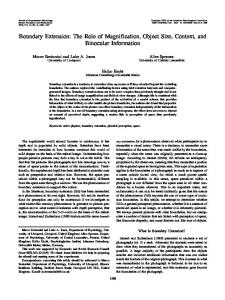
Fi A hierarchy of these requirements is depicted in Figure 5. Figure 6(a) shows a problem frame representation of mandatory requirement R1. A mandatory machine Caller satisfies R1. In Figure 6(b), the Mobile Phone domain is decomposed into three sub-domains Keyboard, Phone Book and Call Log, by projecting R1 onto three sub-requirements R1.1, R1.2
Proceedings of the 12th Asia-Pacific Software Engineering Conference (APSEC’05)
IEEE
M R1
Keyboard
gure 5 Hierarchy model of mobile phone
0-7695-2465-6/05 $20.00 © 2005
Call Log
Dial Controller
R1.1 R1.3
Phone Book
(c)
R4
R3
R2
MA R1.2(DP)
M Caller
Mobile Phone
R1
MA R1.1(DK)
Keyboard
Figure 6(c) is derived from Figure 6(b), expanding the original machine Caller. It shows that there are three multiple adaptor sub-machines, i.e. Key Dialler, Phone Book Dialler and Call Log Dialler, and two mandatory sub-machines, Random Access Memory (RAM) and Dial Controller. The arrowhead lines between solution machines mean call direction. RAM is called by Key Dialler, Phone Book Dialler and Call Log Dialler to get dialling numbers. The three multiple adaptor machines Key Dialler, Phone Book Dialler and Call Log Dialler, are connected to the mandatory machine Dial Controller. It means that R1 can be satisfied through three different sub-domains and the Caller machine will be designed to realize R1 three different ways. The lines connecting Keyboard and Phone Book as well as Keyboard and Call Log mean these pairs of sub-domains share phenomena, typically because access to the Phone Book or Call Log is achieved through a Keyboard.
(a)
(a)
O Email Service
O R2
Mobile Phone
O R2.1(SE)
(b) O Email Service
Email Protocol
M
(b)
O R2
Email O Receiver
O R2.2(RE)
M SA Black & White Controller (BWC) SA
RAM
Colourful Display
SA R3.2(CD)
M R3
(c)
O R2
Email Protocol
SA R3.1(BWD)
Display
O R2.1(SE)
O
Black & White Display M
O R2.2(RE)
(c)
Email O Sender
M R3
Mobile Phone
Display
Colourful Controller (CC)
M
Black & White Display
SA R3.1(BWD) M R3
Colourful Display
SA R3.2(CD)
O: Optional; M: Mandatory
SA: Single adaptor; BWD: Black & White Display;
SE: Send Email; RE: Receive Email
CD: Colourful Display CC: Colourful Controller; BWC: Black & White Controller
Figure 7 Extension of problem frames of R2 Figure 7(a) shows that an optional requirement R2 can be satisfied in domain Mobile Phone by the machine Email Service. The reuse property of Email Service is defined as optional. Figure 7(b) shows R2 is decomposed into two sub-requirements, R2.1 and R2.2 that are all connected to the Email Protocol domain. The reuse properties of R2.1 and R2.2 are mandatory. Figure 7(c) is derived from Figure 7(b) through expansion of the machine Email Service. There are two mandatory sub-machines, Email Sender and Email Receiver, and one mandatory sub-machine RAM. The arrowhead lines between solution machines mean call direction. RAM is called by two optional sub-machines in order to read and write email data. Figure 8(a) shows that the mandatory requirement R3 can be satisfied by a mandatory machine Display in the Mobile Phone domain. Figure 8(b) shows two subdomains, black & white display and colour display, and R3 projects onto two sub-requirements, R3.1 and R3.2. The reuse properties of R3.1 and R3.2 are defined as single adaptor. This means that Display will be designed to realize R3 through two single adaptor machines, Black & White Display Controller or Colour Display Controller that are shown in Figure 8(c).
Proceedings of the 12th Asia-Pacific Software Engineering Conference (APSEC’05) 0-7695-2465-6/05 $20.00 © 2005
IEEE
Figure 8 Extension of problem frames of R3 Figure 9(a) shows that a mandatory requirement R4 can be satisfied by a mandatory machine Camera Service in the domain Mobile Phone. Two subdomains, i.e. Digital Camera and Email Protocol, are added in Figure 9(b) by projecting R4 onto two mandatory sub-requirements R4.1 and R4.2. Figure 9(c) is derived from Figure 9(b) by expansion of the original machine Camera Service into three submachines, Digital Camera Controller, Email Sender and RAM. As Digital Camera Controller satisfies R4.1, its reuse property is defined as mandatory. However, the reuse property of Email Sender was previously defined as optional (Figure 7(c)) to satisfy R2.1. This indicates that R4.2 depends of R2.1. Now there is a choice to be made: either change the reuse property value of the requirement R4.2 from mandatory to optional or change the reuse property value of the machine Email Sender from optional to mandatory. Typically, engineers will make this choice for technical or commercial reasons. Here, we select to change the reuse property of R4.2 from mandatory to optional. The arrowhead lines between solution machines indicate call direction. In this case, RAM is called by two other sub-machines to read/write the photo data.
built into and supplement requirements engineering tools.
(a) M Camera Service
M R4
Mobile Phone
M R4.1(DC) (b)
Digital Camera M R4
M Camera Service Email Protocol
M R4.2(SP)
(c) M Digital Camera Controller
M
Digital Camera
M R4.1(DC)
M R4
Email O Sender
Email Protocol
M RAM
O R4.2(SP)
O: Optional; M: Mandatory; DC; Digital Camera; SP: Send Photo;
Figure 9 Extension of problem frames of R4
5. Discussion The primary advantage of this approach is to provide a mechanism to help engineers identify what product line requirements may need to be common or variable, what product line design solutions may need to be common or variable and to help make explicit how each constrains the other. As a product line evolves, it becomes much more difficult to determine the selection constraints of requirements and machines. The rules provide a repeatable mechanism for consistency checking when building new products, for making improvements to existing products, and for making transparent the trade-offs that often occur between customer needs, technical difficulty and commercial gain. We do not contend that these rules are necessary and sufficient. For example the management of requirements and/or machine obsolescence, and its impact on requirement and machine selection, product line problem frame traceability and product line problem frame configuration management has not been addressed here. Like all rules, there will be exceptions, but we believe the rules we have proposed are realistic and by being repeatable allow computer-aided support to be
Proceedings of the 12th Asia-Pacific Software Engineering Conference (APSEC’05) 0-7695-2465-6/05 $20.00 © 2005
IEEE
The mapping of requirements onto machines does not imply any structure of the machines. It only defines how the variability is represented in the machines and what kind of selections can be made. The organization of the machines happens during the solution design task. In the product line engineering community the notion of feature analysis has been extensively used as a mechanism to tease out the commonality and variability between products. However, in practice the definition of a feature and its relationship to a requirement is not precise. Similarly, the relationship between problem frames, feature analysis and the complementary application of both approaches to solve product line problems requires further work.
6. Conclusion In this paper we have introduced the idea of using problem frames for product line engineering problems and offered some additional notation to support the inherent requirements and machine variability in product line problem frames. It also describes some transitioning rules between product line requirements and machines that can help to manage product line evolution. We illustrated our ideas using a mobile phone worked example.
Reference [1] Clements, L., Northrop, L., Software Product Lines: Practices And Patterns, Addison-Wesley, 2001. [2] Jackson, M., Zave, P., Domain Descriptions. In Proceedings of the IEEE International Symposium on Requirements Engineering, IEEE CS Press, 4-6 January 1993, pp 56–64. [3] Jackson, M., Software Requirements and Specifications, Addison-Wesley, 1995. [4] Jackson, M., Problem Frames: Analyzing and Structuring Software Development Problems. AddisonWesley Publishing Company, 1st edition, 2001. [5] Bleistein, S., Cox, K., and Verner, J., Problem Frames Approach for e-Business Systems. in Proceedings of 1st International Workshop on Advances and Applications of Problem Frames (IWAAPF 2004) at the 26th International Conference on Software Engineering, Edinburgh: IEE, 24 May 2004, pp21-26.
[6] Haley, C.B., Laney R.C., Nuseibeh, B., Using Problem Frames and Projections to Analyze Requirements for Distributed Systems, in Proceedings of the Tenth International Workshop on Requirements Engineering: Foundation for Software Quality (REFSQ'04) at the 16th International Conference on Advanced Information Systems Engineering (CAiSE'04). Riga, Latvia: Essener Informatik Beiträge, 7-8 June 2004. [7] Rapanotti, L., Hall, J., Jackson, M., Nuseibeh, B., Architecture-driven Problem Decomposition. in the Proceedings of 12th IEEE International Requirements Engineering Conference (RE'04), Kyoto, Japan: IEEE, 6-10 September 2004, pp80-89. [8] IEEE (1990): IEEE Standard Glossary of Software Engineering Terminology, IEEE Std 610.12-1990. [9] Savolainen, J., Oliver, I., Mannion, M., Zuo, H., Transitioning from Product Line requirements to Product Line Architecture. In Proceedings of the 29th Annual International Computer Software & Applications Conference, 26-28 July 2005, pp186-195.
[10] Van Gurp, J., Bosch, J., Svahnberg, M., On the Notion of Variability in Software Product Lines, in Proc. Working IEEE/IFIP Conference on Software Architecture (WICSA 2001), 28-31 August 2001, pp 45-54.
Proceedings of the 12th Asia-Pacific Software Engineering Conference (APSEC’05) 0-7695-2465-6/05 $20.00 © 2005
IEEE