Vrijendra Singh. Indian Institute of Information. Technology, ..... [15] U. K. Kumar, and B. S. Umashankar,âImproved Hamming. Code for Error Detection and.
International Journal of Computer Applications (0975 – 8887) Volume 9– No.1, November 2010
An HARQ based Optimized Error Correction Technique Kaustuv Kunal
R. C. Tripathi
Vrijendra Singh
Indian Institute of Information Technology, Allahabad, India
Indian Institute of Information Technology, Allahabad, India
Indian Institute of Information Technology, Allahabad, India
ABSTRACT Errors during data communication are inevitable. Noise in the channel leads to bit error. The paper proposes a matrix based novel bits encoding technique, aim to achieve error correction capability with optimize redundancy. Furthermore an efficient software based decoding algorithm to detect and correct transmission errors is introduced. Here errors include single bit error, multiple bits error and burst errors. The proposed technique maintains high code rate, provides multiple bit error correction capability and can best be implemented as hybrid automatic repeat request (HARQ).
parity check code (LDPC) [8, 9, 10] and turbo code [11, 12]. FEC has reliability issues and ARQ suffers with degrading throughput. A solution is to combine both. Such a scheme is termed as hybrid ARQ [13, 14]. The proposed technique achieves multiple bit correction capability after encoding with high code rate. It uses outlines of product codes and encode message in the form of matrix. Row and column encoding method are dissimilar with an objective to achieve maximum correction capability with minimum redundancy. Our proposed technique when used as HARQ is able to archive high throughput as well as high reliability.
General Terms Error correcting codes, bits encoding, decoding
Keywords Error detection, error correction, forward error correction, automatic repeat request, hybrid automatic repeat request
Proposed technique has been described under next two sub sections information encoding and information decoding. Performance analysis, limitations and assumptions are discussed in section III followed by conclusion. Theoretical and software level implementation are discussed.
1. INTRODUCTION Data communication over the data networks comprising of various carriers like repeater, hub, gateways etc is prone to errors because of reasons such as traffic congestion, delay, network components getting down, packet drop, non receipt of acknowledgements and signaling factors. Automatic repeat request (ARQ) and forward error correction (FEC) are strategies to combat error. ARQ proposes retransmission. Retransmission is not a desirable option particularly in long distance and wireless communication such as through satellite. In FEC, redundancy is added for error prevention. Redundant bits are encapsulated with data bits to form encoded information. However this increases the payload for transmission. Addition of redundant bit is known as channel coding. Error correcting codes (ECC) are used for this purpose. Reliability can be enhanced by combining FEC and ARQ as Hybrid-ARQ (HARQ). First significant ECC as a way of systematic codes was introduced by Hamming [1].He corrected one error per block of code using parity and adjusted it to detect up to two bit error. Elias [2] improved the efficiency with his second order check product codes (figure 1) and further emphasized that it is not necessary to use the same kind of code at each stage of iterative process. BCH code[3,4,5],a multiple bit ECC, is a further generalization of hamming code where 2m-1 bits comprising of mt redundant bits enable correction up to t-bits error. Other significant ECC include Reed Muller code [6, 7], Low density
Figure 1 : Organization of first and second order check digits by Elias
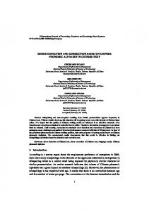
2. PROPOSED TECHNIQUE 2.1 Information Encoding Data bits are encoded into fixed size matrix. This size should be agreed upon and known to both sender as well as receiver. Matrix structure outlines figure1 and is shown in figure 2. A 1
International Journal of Computer Applications (0975 – 8887) Volume 9– No.1, November 2010 novel encoding technique is introduced here, check bits-I represent the number of ones in the data bits. This has two major advantages, first the number of check bits required will be bare minimum for example 31 data bits require just 5 check bits and second, less overhead in extraction of original message [15]. Last row of matrix contains only redundant information i.e. check bits-II, They are column parity bits of matrix and can be constructed using XOR. The check bit –II spans only across single row. In this scenario they comprise of least redundant size in comparison to the scheme of Elias[2]shown in figure 1.Thus in our case encoded matrix has clearly less redundancy than any other multiple bit error correction versions of product codes. Matrix size is chosen based on channel efficiency and the level of correction require. Our scheme provides best possible tradeoff between redundancy and efficiency of retransmission. An example of encoded 8 X 19 bit structure is depicted in figure 2. Here 105 data bits are encoded with 47 check bits. The code rate is 0 .69. Code rate exponentially increases with increase in matrix size. Check bits-II are even parity bits of respective columns.
excluded here and is certainly not a candidate for erroneous row calculation. Step 3: If no column or row is found as erroneous, message will be accepted as correct otherwise correction algorithm, as explained in step 4, will be applied. Step 4: The flow chart of correction algorithm is depicted in figure 3. Recorded erroneous row and erroneous columns are input to correction algorithm. For each erroneous row, matrix entries corresponding to every erroneous column position is checked. A match is said to be found if matrix content is zero for positive difference row, and one for negative difference row. Total number of matches found, in the erroneous row is counted; if this is equal to modulus of row difference then matched matrix entries are inverted. Respective columns are no longer erroneous and are removed from list of erroneous column. The respective row is corrected so it is also removed from erroneous row list. In case of match count not equal to row difference, the same process is repeated with next erroneous row. Initially algorithm traverses through all erroneous rows sequentially. In case of correction in any matrix entry this traversal continues in cyclic manner and revisit previously visited rows which are still erroneous. Reason is that due to deletion of an erroneous column it may possible that revisited row now has equal value of match entries and row difference. If in a whole cycle there is no single matrix entry changed the process exists from loop. Step 5: Finally if no erroneous row or column remains, the received matrix is said to be corrected and receiver accepts the packet, otherwise retransmission is requested.
Figure2: Encoded matrix of 19 bits row and 8 bits column
2.2 Information Decoding Receiver receives encoded message and decodes it to get correct message. Software based hard decision decoding [16] steps are discussed. Decoding process is designed to support HARQ. Step 1: Record all erroneous columns of received matrix. A column is erroneous if bits of that column are not in parity. Step 2: Record erroneous rows with their difference values. A row is erroneous if number of data bits having value as one is found to be different than decimal conversion of binary checks bits. Difference is subtraction value of decimal conversion of check bits to number of ones in data bits of respective row. Clearly difference is positive if the number represented by check bits is more than number of ones in data bits and negative in the opposite case. The last row which contains check bits-2 is
A C code has been written for decoding process simulation. Such a code can be embedded into a decoder device. Few variation of decoder is possible. Figure 2 can be transmitted column wise, received column is checked for parity. If the data bit columns are in parity, receiver accepts data as correct and sender refrain itself from sending check bits columns (i.e. column 16, 17, 18, 19). Only when data columns are not in parity receiver asks for check bits column. Drawback of this scheme is that it will correct only in cases when errors per columns are odd.
3. ANALYSIS 3.1 Redundancy Number of check bits-I should be enough to represent data bits of the row. Table 1 shows check bits for a given range of data bits per row. The relation between check bits-I (c) and data bits (k) of any row is mathematically expressed as: C = [log2 k] + 1 Where [ ] is floor function, [x] will give the largest integer