An Immersive Free-Viewpoint Video System Using Multiple Outer/Inner Cameras Hansung Kim1, Itaru Kitahara1,2, Ryuuki Sakamoto1 and Kiyoshi Kogure1 1
Media Information Science Lab, ATR Keihanna Science City, Kyoto, 619-0288, Japan {hskim, skmt, kogure }@atr.jp 2 Dept. of Intelligent Interaction Technologies, Univ. of Tsukuba Tsukuba Science City, Ibaraki, 305-8573, Japan
[email protected]
Abstract We propose a new free-view video system that generates immersive 3D video from arbitrary point of view, using outer cameras and an inner omni-directional camera. The system reconstructs 3D modes from the captured video streams and generates realistic free-view video of those objects from a virtual camera. In this paper, we propose a real-time omni-directional camera calibration method, and describe a shape-from-silhouette technique for 3D modeling and a micro-facet billboarding technique for rendering. Owing to the movability and high resolution of the inner omni-directional camera, the proposed system reconstructs more elaborate 3D models and generates natural and vivid video with an immersive sensation.
1. Introduction The ultimate goal in visual communication is to realize an interactive 3D imaging system that can provide the feeling of reality as seen in SF movies such as “Star Wars” or “Minority Report.” Although these film are still science fiction, many researchers have tried to develop imaging systems that give realistic impressions of a scene. The range of applications for such a system is obviously enormous. With recent progress in computer and video technologies, many computer vision-based 3D imaging systems have been developed [1][2]. The most important requirement of a 3D imaging system is to create realistic images of dynamically changing scenes. Kanade et al. proposed the concept of “Virtualized Reality” as a new visual medium for manipulating and rendering prerecorded scenes in a controlled environment [3]. The system consisted of a geodesic dome equipped with 49 synchronized environmental video cameras. Recently, Kitahara et al. introduced “Cinematized Reality,” the aim of which is to record unexpected moments and create movie-like footage
by a virtual camera generated from eight environmental cameras [4]. However, these systems have limitations in 3D reconstruction and rendering because they use only fixed environmental cameras. First, they cannot reconstruct an object composed of multiple, disjoint objects. If there is any region occluded from environmental cameras, the reconstructed model may exhibit undesirable artifacts such as phantom volumes. Second, the environmental camera systems suffer a trade-off between the size of modeling space and the resolution of textures due to the limited resolution of the cameras. In the case of the “Virtualized Reality” system by Kanade et al., they used 49 cameras, but the modeling space was only about 6×6×3m. Third, it is difficult to generate fine immersive video. Usually, all environmental cameras are oriented inward from the outside of the modeling space. Therefore, when the virtual camera shoots a movie outward from the inside of the space, the video quality deteriorates because of the difference of resolution between the environmental cameras and the virtual camera. On the other hand, Yamazawa et al. and Ikeda et al. have proposed panoramic movie generation systems that use omni-directional cameras [5][6]. These systems provide adaptive scenes from the viewpoint of their users viewpoints. However, the systems can generate only outward scenes from the real camera position since they cannot overcome the occlusion problem. In this paper, we propose a new free-view video generation system that generates fine immersive 3D video from arbitrary viewpoints using multiple outer/inner cameras. We overcome the problems of previous systems by combining the advantages of the environmental camera system and the omni-directional camera system. In Section 2, we describe the outline of the proposed scheme and advantages of the system. Section 3 describes camera calibration, and Section4 4 explains the 3D reconstruction process. In Section 5 Virtual View Rendering is addressed and the simulation results are presented in Section 6. We conclude the paper in Section 7.
Environmental multiple cameras
3D Modeling
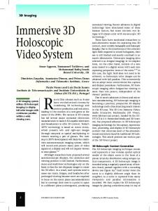
Figure 2. LadybugTM system Omni-directional camera
be calibrated in real-time if any one of the known markers is detected by one of sub-cameras. In this project we are using the Ladybug2TM system produced by Point Grey® shown in Fig. 2 as the omni-directional multi-camera system [7]. The Ladybug camera unit consists of six 1024×768 color CCDs, with five CCDs positioned in a horizontal ring and one pointing straight up. The Ladybug covers approximately 75% of a full sphere and provides video streams at 30 fps for each camera. The following sections describe in detail the algorithms and realization of the system.
Virtual scene from arbitrary viewpoint
Rendering
Figure 1. Proposed 3D video system
2. Immersive Free-Viewpoint System Figure 1 shows the configuration of the proposed system. We set up multiple environmental cameras on the wall and the ceiling to surround the target object and an omni-directional multi-camera inside the working space. All environmental cameras were oriented toward the center of the space to capture almost the same area. When target objects are captured by cameras, each capturing PC segments the objects and transmits the masks and color textures to a 3D modeling server via the UDP (User Datagram Protocol). The modeling server then generates 3D models of each object from the gathered masks. Finally, the server generates a video at the designated point of view with the 3D model and texture information. We can obtain many advantages by inserting an omni-directional multi-camera into the modeling space with the environmental camera system. The greatest advantage of the omni-directional camera is movablity. The camera can be moved to any place in the space to augment the quality of the video with high resolution, or, on other hand, to get rid of interference with working. For example, in a round-table meeting, the system can provide the best scenes of all participants by the omni-directional camera being placed at the center of the table. Second, it is easy to calibrate the omni-directional multi-camera in real-time. Since the omni-directional multi-camera covers a very wide FOV (field of view), all sub-cameras in the camera unit can
3. Camera Calibration Camera calibration refers to determining the values of the camera’s extrinsic and intrinsic parameters. The key idea behind calibration is to write projection equations linking the known coordinates of a set of 3D points and their projections, and to determine the camera parameters. The following camera parameters are extracted for our system. Projection matrix
⎡ p11 P = ⎢⎢ p 21 ⎢⎣ p 31
p12 p 22 p 32
p13 p 23 p 33
p14 ⎤ p 24 ⎥⎥ p 34 ⎥⎦
Extrinsic parameters 3x3 rotation matrix
⎡ r11 R = ⎢⎢r21 ⎢⎣r31
[
3D translation vector T = t x
r12 r22 r32 ty
r13 ⎤ r23 ⎥⎥ r33 ⎥⎦ tz
]
T
Intrinsic parameters Lengths of effective pixel size units: sx and sy Image center coordinates: cx and cy Distortion parameters: k1, k2, p1 and p2
Generally, there are two approaches to camera calibration. The first method is to directly recover the intrinsic and extrinsic parameters, and the second (introduced by E. Trucco and A. Verri [8]) is to estimate the projection matrix first, without solving explicitly for the
y R i , Ti
x
Ci
z M
z R△i, T△i
W
z
y x
x
CD y
RD, TD
Figure 4. Changing coordinate systems in 3D space Figure 3. Camera calibration equipments
various parameters, which are then computed as closed-form functions of the entries of the projection matrix. For environmental camera calibration, we use the second method because it is simpler than the first one, and a projection matrix is used directly to reconstruct the 3D model. For the omni-directional multi-camera, we use the first method because the extrinsic parameters of each sub-camera are updated by the physical relationship between sub-cameras.
3.1. Environmental camera calibration One of the most difficult problems with camera calibration in a daily living area is setting up an accurate 3D world-coordinate system and effectively arranging a series of landmark points, because there are many variations to space size and there may also be many obstacles in that space. If we cover the space with a single scale or a single calibration board, accurate camera calibration is difficult because the scale may be too large, or there may be obstacles occluding some landmarks in the captured image. Our solution is to combine mobile calibration markers and a 3D laser-surveying instrument, which are usually used in civil engineering. Figure 3 shows the equipment we have used in the experiment. To accurately calibrate the camera, it is necessary to obtain many pairs of 3D coordinates (X,Y,Z) in the scene and 2D coordinates (u,v) on an image, thus by using the 3D laser-surveying instrument, we accurately obtain the location of the calibration board in the 3D space. In fact, the measurement error is less than 0.1 mm. By moving the calibration markers to cover the entire 3D space and by measuring its 3D location accurately, it is possible to virtually realize a calibration scale that possesses high shape freedom. Furthermore, our camera calibration method features the two following advantages. First, it is easy to increase the quantity of 3D coordinate data (X,Y,Z) with linear interpolation of the actual measurement values. Second, it is possible to almost automatically detect the landmark
point in the captured images by painting it with a discriminative color.
3.2. Omni-directional camera calibration Once we have calibrated all the camera parameters of the environmental cameras we can use them permanently: they never change since the cameras are fixed to the wall. On the other hand, the extrinsic parameters of the omni-directional camera can be changed by moving it inside the modeling space. Therefore, we need to extract intrinsic and extrinsic parameters independently. However, calibrating all extrinsic parameters of six sub-cameras in real-time is almost impossible because feature points for calibration can be occluded, and detection and calibration for all sub-cameras are time-consuming processes. We propose extracting the extrinsic parameters of the other cameras from that of one sub-camera by using the geometrical relationship between sub-cameras. Changing from one coordinate system to the other system can be described as follows, where R1,2 and T1,2 are a rotation matrix and a translation vector from the coordinate 1 to coordinate 2, respectively. M 2= R1, 2 M 1 + T1, 2
(1)
Figure 4 shows the relationship between the global coordinates and those of each camera. When CD is a camera coordinate of the reference sub-camera and Ci is that of the other camera, the following relationship can be derived from Eq (1) and Fig. 4. ⎧⎪M Ci = RD M W + TM ⎨ ⎪⎩M Ci = RΔ (RD M W + TM ) + TΔ ⎧ Ri = RΔ RD ⇒⎨ ⎩Ti = RΔ TM + TΔ
(2) (3)
In Eq. (3), R△ and T △ are stationary values for each sub-camera because all sub-cameras in Ladybug have a fixed geometrical relationship. Therefore, once we extract
Captured Image
Voxel V(X,Y,Z)
I1
Camera C3 Camera C1
Estimated 3D Shape M(X,Y,Z)
P2
P1
I2
Pv
Captured Image
Camera C2
Iv Virtual Camera
Figure 5. 3D reconstruction by shape-from-silhouette
Figure 7. Synthesis of a novel view with an estimated 3D shape Voxel
Micro-facet Billboarding micro-facet billboard
voxel
3D Object
3D Object
Figure 6. Octree structure
Input Image1
the parameters R△ and T△ for each camera by Eq. (4) in advance, we can calculate all the other extrinsic parameters from the parameters of one camera. ⎧⎪ RΔ = Ri RD ⎨ ⎪⎩TΔ = Ti − RΔTM −1
(4)
In our system, we set up feature points on the ceiling of working space. The vertical sub-camera in Ladybug is used for real-time extrinsic camera calibration.
4. 3D Reconstruction Since the 1980s, many works on computational models for computing surface shape from different image properties have been produced [9].In order to reconstruct the 3D shape of the captured object, we employ a shape-from-silhouette method. The shape-from-silhouette method is a very common way of converting silhouette contours into 3D objects [10]. Silhouettes are readily and easily obtainable and the implementation of the shape-from-silhouette method is generally straightforward. Figure 5 illustrates the relation of the multiple cameras and the voxels that are set up in the 3D space. Each camera is labeled as Cn, a captured image with the camera as In (n=1,…,N), and each voxel as V(X,Y,Z). Now, for example, let us assume that V(X,Y,Z) is a voxel inside the modeling space and Ip is a subset of In that include the projected point of V in their imaging area. If the 3D position of V is inside the 3D object, V must be projected onto the foreground regions of all the images Ip. Therefore, if there is any single projected point located in
Input Image2
Reverse Sequence
Virtual Image
Input Image2
Normal Ascending Order
Virtual Image
(a) Texture mapping on voxels (b) Micro-facet billboarding Figure 8. Texture mapping process
the background region in the images Ip, the voxel V is carved out from the 3D shape model. As a result, we can estimate the entire 3D object’s shape by examining every possible position of the voxels V(X,Y,Z). Testing all the points in a modeling space is, however, a very time-consuming process and results in excessive data. Therefore, we use an octree data structure for modeling [11]. For each voxel of a given level, 27 points (i.e., each corner and the centers of the edges, faces and a cube) are tested. If all checking points are either included in or excluded from an object, the voxel is assigned as a full or empty voxel, respectively. Otherwise, the voxel is split into eight sub-voxels and is tested again at the next refinement level. Figure 6 shows the structure of the octree. This structure dramatically reduces the modeling speed and the amount of data.
5. Virtual View Rendering Figure 7 illustrates the geometric relation between a scene point M(X,Y,Z), captured images In, and the image plane Iv of a virtual camera. We consider that the 3D model represents only the correspondence among the input multiple videos concerning a scene point M. The model
2.5m
5.5m 5.5m
Figure 9: Layout and captured images by the propose system
tells us where a point M exists in each captured image. Furthermore, when the position and orientation of the virtual camera are specified, the projective relation between a scene point M and a point on the image Iv is defined with a projective transformation matrix Pv. Here, we address the rendering of a scene point M(X,Y,Z) on the image of virtual camera Iv. Suppose a scene point M is projected to a point on the image Iv with the projective transformation matrix Pv, and M is observed in several captured images In. To select the most suitable texture to be used for rendering, we investigate occlusion among objects, the orientation of objects’ surfaces, and the distances from the surface to the real cameras. Fundamentally, a voxel-based structure is not a very good approximation for the object surface since the mesh obtained from the voxel is too dense, and the orientations of the mesh faces suffer from severe quantization as they are strictly aligned with the coordinate axes. A micro-facet billboarding technique is employed to solve this problem [12]. This technique was originally developed in photometric rendering research to express a 3D object that has fine texture, like a flowing coat or a jagged shape. Nevertheless, though the advanced 3D laser range finder can accurately measure 3D shape, the measurable spatial resolution is still lower than that of a high-resolution digital camera. Therefore, if the 3D object is described at a lower resolution, appearance information on the captured images will be wasted. On the other hand, the billboarding technique approximates a 3D object’s shape to a single plane and expresses the object’s appearance by mapping its captured image. This technique has the advantage of not wasting the resolution of captured images, even if an accurate 3D shape is not available. The micro-facet billboarding technique, which implements the advantage of the billboarding technique on 3D modelling,
can express more complicated shapes by encrusting micro-facet billboards onto the surface of the estimated 3D shape, while still applying all the advantages of the billboarding technique. In Fig. 8, we illustrate the difference of the texture mapping process between the voxel volume and the micro-facet billboarding technique. Since the normal vector of each surface of a voxel differs greatly from the correct normal vector of the 3D object’s surface, when we generate a virtual image with mapping captured images onto the estimated voxel volume, the order of the appearance of the 3D object is not often retained. As a result, many dots and cracks are observed on the surface of the 3D object. On the other hand, as shown in Fig. 8(b), the micro-facet technique absorbs the difference by controlling the orientation of each billboard. Consequently, the order of the appearance of the 3D object is always maintained.
6. Simulation Results We have implemented a distributed system using nine PCs, seven calibrated USB2.0 color cameras and one Ladybug2. The size of capturing space was about 5.5×5.5×2.5 m, and seven environmental cameras were set on the wall to surround the space. All cameras were oriented to observe the center of the space. Seven Pentium IV 2.8-GHz PCs for environmental cameras and one Pentium IV 3.6-GHz PC for Ladybug were used in order to capture a video stream from each camera and segment objects at 20 fps (frames per second). An intensity-based background subtraction method was used to segment the foreground and background regions in the input multiple images [13]. The segmentation masks and texture information are sent via UDP over a 100-Mbps (bits per second) network to the modeling and rendering PC. The
Figure 10: Evaluation of calibrated parameters
modeling and rendering PC features a Pentium IV 3.6-GHz CPU and a FireGL V3100 graphic accelerator. Figure 9 shows a set of snapshots from videos recorded with this layout. However, modeling and rendering speeds with the PC were not enough to perform them in real time so that the modeling and rendering process were done off-line in this experiment.
6.1. Real-time Ladybug calibration The Ladybug can be moved in the space according to efficiency of capturing or inconvenience to working people. Therefore, all extrinsic parameters of sub-cameras should be updated in real-time. The system calibrates one of the sub-cameras using a chessboard pattern attached on ceiling, and calculates all parameters of the other sub-cameras using Eq. (3) in real time. Because each lens of Ladybug has a viewing angle exceeding 80 degrees, the pattern can be captured at any place in the capturing space. We tested the accuracy of the extracted parameters by projecting global points measured by the 3D laser-surveying instrument to the image plane (up, vp). The error between projected points (up, vp) and detected image point (uc, vc) by corner detection was calculated. We tested 48 points in a chessboard pattern for each sub-camera. In Fig. 10, red circles represent 3D points projected onto the image planes, and Table 1 shows the mean and standard deviation (SD) of errors in pixels for each camera. The average errors were less than 0.5 pixels in the horizontal (u) and vertical (v) directions, and the distance error (d) was less than 0.8 pixels. TABLE 1. PERFORMANCE EVALUATION OF THE ESTIMATED PARAMETERS
Mean (pixels)
SD (pixels)
Subcamera
u
v
d
d
Cam1 Cam2
0.4611 0.4454
0.3091 0.4713
0.6295 0.6566
0.3401 0.3425
Cam3
0.4822
0.4598
0.7346
0.4130
Cam4
0.4633
0.4362
0.6928
0.3694
Cam5
0.4381
0.3510
0.6415
0.3409
(a) Without Ladybug (b) With Ladybug Figure 11: Results of 3D modeling
6.2. 3D reconstruction To verify the performance of the proposed system, we compared reconstructed models without/with the omni-directional camera. All images from the environmental cameras were captured at a resolution of 640×480 and the Ladybug at 1024×768 for each sub-camera. The 3D space was modeled at a resolution of 300×300×200 on a 1×1×1-cm voxel grid. Segmentation in this experiment was performed in a semi-manual way in order to avoid errors in the 3D model caused by segmentation error and to confirm the contribution of the omni-directional camera to modeling. Figure 11 shows 3D models generated by the shape-from-silhouette method without/with the Ladybug, respectively. We can see that the final models generated without Ladybug are coarse and failed in carving occluded areas from environmental cameras. On the other hand, the models generated using both environmental cameras and the Ladybug look more natural because the redundancies in the models are carved out by the inner cameras.
6.3. Virtual view rendering By using the algorithm described above, the proposed system synthesizes a 3D video from the position of the virtual camera. Because the system is installed in an environment that might have unfavorable conditions for 3D
Figure 12: Generated micro-facet billboards and selected cameras for texturing
(a) Without Ladybug (b) With Ladybug Figure 14: The effectiveness of the inner camera
(a) Texturing on voxels
(b) Texturing with micro-facet billboarding Figure 13: The effectiveness of the micro-facet billboarding
modeling such as a typical office environment, the reconstructed 3D shape includes many computational errors. Thus, if we just map the captured image as texture information, the quality of the generated 3D video will suffer seriously. As a solution, we employ the micro-facet billboarding technique to curb the improper influence of such errors. Each micro-facet billboard corresponds to a voxel; in other words, the center of both corresponding components of the 3D model should lie at the same 3D position. The orientation of the micro-facet billboards is set to ensure that the normal vector of the billboard and a virtual camera’s line of sight are parallel, just as with the ordinary billboard technique. To reduce the computational complexity, the system generates micro-facet billboards only on the surface facing the virtual camera, and selects textures of the closest camera by calculating distance and angles from the virtual camera to real cameras for each micro-facet billboard. In the proposed system, we gave priority to the Ladybug in camera selection because the Ladybug has a higher resolution than the environmental
cameras in addition to a very wide FOV. Figure 12 shows generated micro-facet billboards and selected cameras for each facet. The color of the surface corresponds to the color of each camera. As a result, the micro-facet billboarding technique covers the appearance deficit generated by errors in 3D shape estimation as shown in Fig. 13. We also tested the effectiveness of the omni-directional camera inside the modeling space on texturing. Figure 14 shows the same model textured without/with the Ladybug. When we use the Ladybug, the virtual camera can capture much more distinct textures because the Ladybug has a higher resolution and is placed nearer to the objects. The other advantage of using the omni-directional camera is that it can be moved to the optimal position to augment the video quality. On the second image set in Fig. 14, the Ladybug placed in a low position provides very good textures in looking up camera angles. Finally, Fig. 15 shows snapshots of the generated 3D free-viewpoint videos. It is clear that the system generally renders natural scenes from any point of view.
7. Conclusion We have presented a complete 3D imaging system using multiple outer/inner cameras. The system reconstructs 3D models from the captured video streams and finally displays realistic images of those objects from arbitrary viewpoints. We proposed a real-time omni-directional multi-camera calibration method, and used the shape-from-silhouette technique for 3D modeling and the micro-facet billboarding technique for rendering to generate fine free-view video. Cooperation between
Figure 15. Snapshots of the generated 3D free-viewpoint videos
environmental cameras and the omni-directional camera solved the limitation of previous systems and provides more natural and vivid videos. Future work will include improving segmentation performance, boosting the processing speed, and developing a texture-blending algorithm from multiple images to generate more natural surface texture.
[5]
[6]
Acknowledgement This research was supported by the National Institute of Information and Communications Technology.
References [1] M. Gross, “Blue-c: A spatially immersive display and 3D video portal for telepresence,” SIGGRAPH03, pp. 819-827, 2003. [2] X. Wu, T. Matsuyama, “Real-time active 3d shape reconstruction for 3d video,” Proc. International Symposium on Image and Signal Processing and Analysis, pp. 186-191, 2003. [3] T. Kanade, P. W. Rander, and P. J. Narayanan, “Virtualized Reality: Constructing Virtual Worlds from Real Scenes,” IEEE Multimedia, Vol. 4, No. 1, pp. 34-47, 1997 [4] I. Kitahara, R. Sakamoto, M. Satomi, K. Tanaka, and K. Kogure, “Cinematized Reality: Cinematographic Camera Controlling 3D Free-Viewpoint Video,” 2nd IEE European
[7] [8] [9] [10] [11]
[12]
[13]
Conference on Visual Media Production (CVMP2005), pp. 154-161, (2005) K. Yamazawa, H. Takemura, and N. Yokoya, “Telepresence system with an omnidirectional HD camera,” Proc. 5th Asian Conf. on Computer Vision (ACCV2002), Vol. II, pp. 533-538, Jan. 2002. S. Ikeda, T. Sato, and N. Yokoya, “Panoramic movie generation using an omnidirectional multi-camera system for telepresence,” Proc. 13th Scandinavian Conf. on Image Analysis (SCIA2003), pp. 1074-1081, July 2003. http://www.ptgrey.com/ E. Trucco and A. Verri, Introductory Techniques for 3-D Computer Vision, New Jersey: Prentice Hall, 1998. L. G. Shapiro and G. C. Stockman, Computer Vision, chap. 12, New Jersey: Prentice Hall, 2001. W. Matusik, Image-Based Visual Hulls, MS Thesis, MIT, 1997. R. Szeliski, “Rapid octree construction from image sequences,” CVGIP: Image Understanding, vol.58, pp.23-32, 1993. S. Yamazaki, R. Sagawa, H. Kawasaki, K. Ikeuchi, and M. Sakauchi, “Microfacet billboarding,” Proc. 13th Eurographics Workshop on Rendering, 2002, pp. 175–186, 2002 H. Kim, I. Kitahara, K. Kogure, N. Hagita, and K. Sohn, “Sat-Cam: ‘Personal Satellite Virtual Camera,’” Proc. PCM 2004, LNCS. vol. 3333, pp. 87-94, Nov. 2004.