AN IMMERSIVE 3D VIDEO-CONFERENCING SYSTEM USING SHARED VIRTUAL TEAM USER ENVIRONMENTS Peter Kauff
Oliver Schreer
Heinrich-Hertz-Institut Einsteinufer 37 D-10587 Berlin ++49 30 31002-615
Heinrich-Hertz-Institut Einsteinufer 37 D-10587 Berlin ++49 30 31002-620
[email protected]
[email protected]
ABSTRACT Videoconferencing is going to become attractive for geographically distributed team collaboration, specifically to avoid travelling and to increase flexibility. Against this background this paper presents a next generation system – a 3D videoconference providing immersive tele-presence and natural representation of all participants in a shared virtual meeting space to enhance quality of human-centred communication. This system is based on the principle of a shared virtual table environment, which guarantees correct eye contact and gesture reproduction. The key features of our system are presented and compared to other approaches like tele-cubicles. Furthermore the current system design and details of the real-time hardware and software concept are explained.
Categories and Subject Descriptors H.4.3 [Information Systems Applications]: Communications Applications – Computer conferencing, teleconferencing, and videoconferencing.
usability and effectiveness when first system implementations were introduced more than one decade ago. However, most former deficits were caused by a considerable lack of bandwidth capabilities, inefficient video compression techniques and insufficient knowledge in presence engineering. In meanwhile, video conferencing has been advanced rapidly and is regarded as a high-return investment for decision-making in a wide gamut of applications, from international research projects, world-wide operating companies to global investment banking, and many others. Related examples can frequently be found in the service framework of the current activities of the US Internet2 consortium - such as the Access Grid (AG), the Virtual Rooms Video Conferencing Service (VRVS), the Virtual Auditorium of Stanford University or the recently established Global Conference System [1][2][3][4]. Based on high-speed backbone networks like Abilene, STAR TAP, DANTE, GWIN oder TransPac, these systems offer high-quality audio and video equipment with presence capabilities for different applications like tele-teaching, tele-conferencing and/or tele-collaboration.
General Terms Algorithms, Performance, Design, Experimentation, Human Factors, Standardization, Verification.
Keywords Next generation video conference, presence research, teleimmersion, shared virtual table environment, tele-cubicles, 3D video processing, disparity estimation, MPEG-4 video coding, arbitrarily shaped video objects, image based rendering.
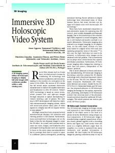
1. INTRODUCTION Although it was generally agreed that video conferencing represents a potential improvement over the singular modality of typical voice circuits, many people have been concerned about its Figure 1. Objective of Immersive 3D Videoconference. Permission to make digital or hard copies of all or part of this work for personal or classroom use is granted without fee provided that copies are not made or distributed for profit or commercial advantage and that copies bear this notice and the full citation on the first page. To copy otherwise, or republish, to post on servers or to redistribute to lists, requires prior specific permission and/or a fee. CVE’02, September 30–October 2, 2002, Bonn, Germany. Copyright 2002 ACM 1-58113-489-4/02/0009…$5.00.
Nevertheless, these systems are still limited in their support of natural human-centred communication. Most of them are windowbased multi-party applications where a mass of single-user images are presented in separated PC windows, most preferably displayed in full body size at large video walls and often in combination with other window tools [1][2]. However, due to missing specifications on the relation between capture and display
geometry, main features of human-centred communication like body postures, subtle movement, eye contact, gaze direction and room acoustics can not be reproduced on principle by these systems [3]. Therefore other systems have been specialised to two-party conferences based on a point-to-point connection between two user groups. In this case each group is seating at one end of a long conference table whereas the opposite end terminates in a large screen showing the counterpart at the remote site. As a consequence, the conferees get the impression of sitting at one table. Furthermore, as all members of one group are sitting close together and the virtual viewing distance between the two groups is quite large, eye contact, gaze direction and body language can be reproduced at least approximately. However, as mentioned above, such videoconference table systems are usually restricted to two-party point-to-point scenarios. Two commercial state-of-art examples can be found under [24] and [25]. The main restriction in all these systems is the usage of conventional 2D video, often coded by MPEG-2 or H.263. In fact, in the most general case, human-centred communication in videoconferences means that every participant gets his very individual perspective view of the conference scene – a feature that requires an interactive control of a virtual camera in a synthetic 3D world. This is a main issue of basic research on collaborative virtual environments (CVE) since years. A common theme of all these efforts is to exploit the benefits of teleimmersion, often in that way that the participants will have the impression of being present in a shared virtual table environment (SVTE) suggesting spatial proximity, enabling a higher degree of natural interaction and effective collaboration.
to former proposals it combines the benefits of video-based telecubicles and VR-based CVE’s in one common scheme enabling conferees located in different geographical places to meet around a virtual table, appearing at each station in a way to create a convincing impression of being present in a real conference situation (see Figure 1). From the signal processing point of view, the 3D video processing of this prototype represents the main difficulty of the entire system design. It provides the basic 3D feature enabling the participants to view each other from the proper perspective, with realistic eye contact and supporting head motion parallax. Therefore, the 3D video processing chain and software implementations are described in detail in section 5. Finally, the conclusions in section 6 summarize the work and give an outlook on possible extensions of the system.
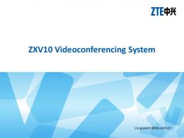
2. NEXT GENERATION SYSTEMS 2.1 Tele-Cubicles An attractive SVTE approach known from the past is the one of tele-cubicles [5][6][7]. A common feature of these proposals is a special system set-up, where the participants are situated symmetrically around the shared table, with each conferee appearing on an own screen (see Figure 2). Note that the symmetric geometry of this set-up guarantees eye contact, gaze awareness and gesture reproduction. Thus, everybody in the session can observe under correct perspective who is talking to whom or who is pointing at what. For example, if the person in front of the terminal in Figure 2 talks to the one on left while making a gesture in direction of the right one, this third person can easily recognize that the two others are talking about him.
First approaches in this area were limited to strictly graphical environments using avartars for representing the remote conferees. A lot of systems have been proposed in this context during the last decade. One example for theses world-widely spread research activities was the former Europe ACTS project COVEN who demonstrated the benefits of the SVTE concept by a networked business game VR application in 1997 [26]. Later approaches were more and more focused on a seamless integration of 2D video images or even 3D video avatars into CVE’s to increase realism [27][28]. Some of these approaches were driven by the MPEG-4 multimedia standard that offers new powerful coding and composition tools for such purposes [13] [29]. Further SVTE-based system proposals are more video-based as, for example, the ones using tele-cubicles where the remote conferees appear at separate video screens spatially arranged in an SVTE-like set-up [5][6]. The main objective of these systems is to offer rich communication modalities as similar as possible to those used in a real face-to-face meeting (e.g., gestures, gaze awareness, realistic images, correct sound direction, etc) and to exceed the limits of conventional video-conferencing on one hand an VR-based CVE approaches on other hand, which may impoverish communication (e.g., face-only images in separate windows, unrealistic avatars, missing eye contact). Against this background, the most attractive approaches on next generation systems and related applications are reviewed in the following section. Then section 3 briefly explains the basic concept of shared virtual table environments (SVTE). Section 4 outlines the system architecture as well as some hardware details of our prototype demonstrator on a SVTE conference system. In contrast
Figure 2. Experimental set-up of NTII at UNC [7]. However, while the tele-cubicle concept seems to hold merit, there exist a lot of severe disadvantages and unsolved problems. First of all, the specifically arranged display surfaces appear as 'windows' into the offices of the other conferees, resulting in a restricted mediation of social and physical presence. Furthermore, ideally suited for a fixed number of participants (e.g. three in the set-up from Figure 2) and limited to single-user terminals only, the tele-cubicle concept does not scale well. Any addition of further terminals requires a physical re-arrangement of displays and cameras, simply to adjust the geometry of the SVTE set-up to the new situation. Finally, it is difficult to merge the tele-cubicle
concept with the philosophy of shared virtual working spaces. Although the National Tele-Immersion Initiative (NTII) has already demonstrated an integration of tele-collaboration tools into their experimental tele-cubicle set-up from Figure 2, the possibility of joint interactions is limited to two participants only, whereas shared workspaces with more than two partners are hard to achieve because of the physical separation of tele-cubicles windows.
3. THE SVTE CONCEPT The basic idea of the SVTE concept is to place 3D video reproductions of a given number of participants at predefined positions of a shared virtual environment. For this purpose the conferees are captured at each terminal by a multiple camera setup and the desired 3D video representation of the local conferee is extracted from this multi-view images (see Figure 4).
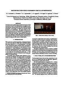
2.2 Virtual Team User Environment Due to these shortcomings, a new SVTE concept has be proposed for the first time by the IST project VIRTUE under the designation Virtual Team User Environments (VIRTUE) [8][9]. It offers all benefits of the tele-cubicle approach, but extends it towards an integration of the SVTE into shared virtual working spaces. The main idea is to combine the SVTE metaphor with the one of mixed realities in a twofold manner. At first, a seamless transition between the real working desk in front of the display and the virtual conference table at the screen gives the user the impression of being part of an extended perception space. Secondly, the remote participants are rendered seamlessly and under correct perspective view into the virtual conference scene. As an example for such a system, Figure 3 shows the VIRTUE set-up which has been demonstrated the first time to the public at the IST Event 2001 last December in Duesseldorf, Germany.
Figure 4. 3D Capturing for a 3-party conference. Then the 3D video objects of all conferees are grouped virtually around the shared table. Ideally, this is done in an isotropic manner in order to obtain social and geometric symmetry. Hence, in the case of a three-party conference the participants form an equilateral triangle. In the case of four parties it would be a square, and so on. Following such generic composition rules and knowing the number of participants, the same SVTE can be built at each terminal from previously loaded scene descriptions and the received 3D video streams. Virtual Camera
Figure 3. Example of VIRTUE set-up. In the following chapters we will present a similar system design called Immersive 3D Videoconferencing (I3DVC) [10]. It is based on the VIRTUE approach (i.e. it uses the same prototype set-up depicted in Figure 3), but in contrast to VIRTUE it utilises the state-of-the-art multimedia standard MPEG-4. Hence, it is the first video-based SVTE implementation leaving the stage of experimental test platforms and entering the area of prototype developments. Due to usage of the MPEG-4 signalling protocol DMIF, a sophisticated 3D video processing and the MPEG-4 scene description language BIFS, the system architecture supports an arbitrary terminal set-up, interoperability with other terminal configurations and scalability in terms of number of participants – and it makes it open for future extensions and developments towards immersive tele-collaboration, multi-user terminals and joint applications.
Figure 5. Rendering of virtual 3D conference scene. Based on this generic scene composition, individual views of the virtual conference environment can then be rendered by using a virtual camera (see Figure 5). Note that each conferee has a predefined place at the virtual table. Thus, globally, the virtual camera has to be positioned to the same place to generate the desired individual view of the scene. Locally, the position of the virtual camera has to move coincidently with the current position of the conferee's head, which is permanently registered by a head tracker. Thus, supposing that the geometrical parameters of the multi-view capture device, the virtual scene and the virtual camera are well fitted to each other, it is ensured that all conferees see the scene under the correct perspective view, even while changing their own viewing position.
This geometrical coincidence provides all desired attributes mentioned in the introduction – eye contact, gaze awareness, gesture reproduction, natural conference situation and high amount of realism. In addition, the support of head motion parallax allows the conferees to change the view knowingly in order to watch the scene from another perspective, to look behind objects or to look at a previously occluded object.
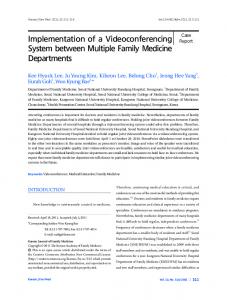
4. THE PROTOTYPE ARCHITECTURE 4.1 System Outline Figure 6 outlines the system architecture of our I3DVC prototype design. After multi-view capturing, the video frames are segmented to separate the person's silhouette and to suppress the image background. As a result, the conferees are represented by arbitrarily shaped video objects, which can be integrated seamlessly into virtual environments. To extract depth information, the shaped video objects are first rectified and then disparity estimation is applied to the rectified objects yielding dense disparity maps. Subsequently, shaped video objects and associated disparity maps are combined to one compact representation form which can efficiently be encoded, using an MPEG-4 codec. Client 1
Head Tracker
Segmentation
User Interface
Rectification
MPEG-4 Compositor Synchronization Layer
Disparity Estimation
3D-Warp
3D View Combining MPEG-4 Encoder Conference Controler
RTP / UDP / IP
BIFS Decoder
MPEG-4 Decoder
HTTP TCP/IP
RTP UDP/IP
Moreover, at this point we take advantage of another important feature of the MPEG-4 standard, because BIFS also allows dynamic updates of the scene description. Due to this property, we can for example change the number of participants and – with it – the SVTE composition rules while running a session. Thus, conferees can join or leave running sessions without violating the SVTE principle. In the same manner, we can add new scene objects or manipulate existing ones – an aspect being particularly important for joint applications in shared virtual working spaces. A special scene and conference server coordinates these changes by receiving requests from particular terminals and by sending related BIFS updates to all participating terminals. Finally, an MPEG-4 compositor is used for rendering purposes. This compositor is able to handle user events (head tracker, interaction with scene content, etc.) as well as scene updates sent by a server as mentioned above. In our case, the MPEG-4 video objects are processed via a 3D warp using image-based rendering techniques before they are integrated into scene composition. Depending on the current input from the head tracker, this 3D warp calculates the correct perspective view from the received 3D video data and inserts this adapted view as an rendered 2D video into the BIFS scene. Note that the usage of virtual cameras and generic 3D video representations encapsulates capturing and rendering. Thus, terminals with quite different camera and display arrangements can be used in the same conference session. This also holds for the usage of mono- and auto-stereoscopic displays. Although the current system is designed for 2D displays, the concept can be extended towards auto-stereoscopic displays, simply by adding a second virtual camera. It is even open for the usage of autostereoscopic multi-user displays as the one currently under investigation in the IST project ATTEST [11]. All these features emphasise the open structure of the system enabling interoperability between SVTE systems with different terminal set-ups and display types.
4.2 Hardware Details Network Client 2
Client 3
Conference Server
Scene Server
Figure 6. Outline of I3DVC prototype. Here, the system concept takes advantage of several particular features of the MPEG-4 multimedia standard. On one hand MPEG-4 allows the coding of arbitrarily shaped video objects. On other hand it provides auxiliary grey-scale alpha planes to transmit additional pixel data associated to the original colour data. This auxiliary planes can be used to transmit the disparity maps jointly with the video objects. After MPEG-4 encoding the data are transmitted to other participating terminals by RTP via IP networks. Simultaneously, the terminal receives video streams from the other conference partners and decodes them by multiple MPEG-4 video decoders. The shaped video objects are then synchronised to each other as well as to other scene objects (audio, events, etc.) and integrated into the SVTE scene represented by the MPEG-4 description language BIFS. These BIFS data are usually loaded in advance via HTTP during an initialisation phase.
Although the complexity of the I3DVC system is quite high, it is our strong believe that such a system must be implemented in standard PC technology. The philosophy here is to develop the whole system exclusively in software such that it can easily be ported onto next generation processors. Hence, reduction of overall complexity becomes a matter of time. At the moment, however, we need three high-end PC’s for each terminal. Moreover, the challenging task of parallel real-time processing of multiple TV signals in full resolution according to CCIR Rec.601 requires additional equipment, especially video-in/out interfaces and special high-speed video links in order to release the PCI bus from high transfer rates between different processor units. Therefore we have developed a PCI-based multi-processor board called VPS [12]. It is equipped with four TriMedia digital signal processors TM 1300, each providing fast video interfaces (see Figure 7). Several VPS boards can be cascaded without loading the PCI bus. The software running at the VPS boards is based on standard C++ code and can be ported on the motherboard as soon as faster processor units and PCI transfers will be available. In this sense, the usage of VPS boards is considered as interims solution setting up the system with today’s technology.
because especially shadows at the table can usually not be avoided, even not under optimal illumination conditions. The effect of shadow detection and the final segmentation result is shown in Figure 9.
Figure 7. Photograph of the VPS board.
5. 3D VIDEO PROCESSING 5.1 Foreground/Background Segmentation In the finally rendered scene the conferees appear as arbitrarily shaped video objects, seamlessly integrated into the virtual environment. Hence, the captured video images are segmented first and are subsequently processed as shaped objects. This extraction of the conferees portrayal from the image background has the additional advantage that the amount of computations can be reduced at least by a factor of 2 due to the reduced number of pixels in the foreground object. This initial segmentation algorithm is based on a real-time solution of a former non-immersive implementation of a virtual conference system, operating on reduced quality and frame rate, the so-called “Virtual Meeting Point” [13]. It is a change detection scheme, comparing the current image of a particular conferee with a pre-known reference image of the corresponding background scene (see Figure 8).
Figure 9. Segmented foreground without (left) and with (right) shadow detection.
5.2 Rectification In the I3DVC set-up, two camera pairs capture independently the local participant from the left and right side according to the viewing direction of the virtual participants on the display. Due to the small distance between the conferee and the display, the cameras have to be mounted highly convergent (see Figure 10). In the final view synthesis, this camera geometry is not optimal for computational reasons. Therefore, a simple linear transformation on both stereo images generates rotated and distorted views, which are equal to a parallel camera set-up [14]. The result of rectification is depicted in Figure 11.
Figure 10. Segmented original images.
Figure 8. Static background (left), complete scene (middle). This requires the capture of a background reference image, which is taken in an initialisation phase at the beginning of the conference session. During the conference session, the object region is detected by an analysis of the pixelwise differences between the current input image and the background reference image. In addition, the reference image is permanently updated to be able to cope with slight changes of illumination or scene content. This baseline algorithm has been improved in speed and quality in order to meet the real-time constraints for full CCIR601 resolution and full video frame rate. In addition, its performance has been improved by adding a fast and efficient shadow detection tool [21]. In the I3DVC application this is particularly important,
Figure 11. Rectified images.
5.3 Disparity & Depth Analysis To extract the required 3D representation, the depth of the captured video object is analysed on the basis of the rectified images. This is done by so-called disparity matching between multi-view images – a process searching for pixel correspondences referring to projections of the same 3D point onto different position in the image planes. In this context we
have developed a new hybrid block- and pixel-recursive approach, which is able to compute the disparity fields on full resolution in real-time on a state-of-the-art PC (see [15] for details). Apart from a considerable reduction of computational load, this algorithm also leads to spatio-temporally consistent depth maps, particularly important for later novel view synthesis, since temporal inconsistencies in disparity sequences may cause annoying artefacts in the final synthesised view. During algorithmic development it turned out that the regions around the hands are the most critical for disparity analysis. Especially, occlusions caused by the hands, arms or head may result in visible artefacts in the virtual view. The same holds for self-occlusions at object borders yielding image regions, which are only seen by one of the cameras. To cope with these special occlusion problems, the disparity maps have to be post-filtered by dedicated segmentation-driven algorithms [16]. In a first step critical regions are detected by a consistency check between disparity fields for a leftÆright and a rightÆleft match (see Figure 12). The unreliable disparity values are marked in black. The images give a realistic impression of the depth of the scene as well as an idea of the occluded areas near the hands or in other regions.
Figure 12. Disparity fields with occluded areas. Furthermore, an additional tracking algorithm has been developed to provide more accurate segmentation information at the hand areas. This particular module is based on skin colour segmentation and tracking of bounding boxes surrounding the hand regions in each image (see Figure 13, left). The resulting masks of hand tracking and segmentation are shown in the right image of Figure 13. They are used to improve the results of the hybrid disparity estimation algorithm in the post-processing step. This is essential, especially in case of occlusions within the object. new box position new center
previous box position
Figure 13. Tracking and segmentation of hands.
Figure 15. Simple interpolation (left) and segmentation-driven extrapolation (right) of corrected disparity maps. Based on this segmentation masks, the disparity fields in occluded areas can be post-processed and filled efficiently by suitable extrapolation techniques. Figure 14 shows estimated disparity maps with and without a segmentation-driven post-processing. Figure 15 presents the result of a virtual view synthesis as a closeup of the critical region around the hand. Both figures demonstrate that most of the artefacts could be eliminated. The depth discontinuity has been preserved and synthesised with good quality.
Figure 15. Virtual view synthesis using a simple interpolation (left) and segmentation-driven extrapolation (right).
5.4 Head Tracking The perspective view of the scene presented on the display depends on the viewer's position. This requires an accurate estimation of the viewer's position in the 3D space, which is accomplished by the head-tracking module. The chosen approach is based on a skin colour segmentation technique jointly with a facial feature tracker searching eye positions. Due to the videoconference scenario, several assumptions can be made to facilitate the tracking of the viewer's head. The resulting 2D positions of the eyes in two images can then be used for an accurate calculation of the 3D position of the head.
5.5 Virtual View Synthesis by 3D Warp The calculated head position and the analysed depth of the transmitted video objects provide sufficient information to synthesize novel virtual view of the remote conferees. Several important approaches have been pursued and theoretical solutions can be found in [17][18][19]. However, none of them have been applied successfully in real systems except in rather constrained environment. For practical applications, two critical issues should be considered: real-time implementation and occlusion handling.
A very fast and efficient view synthesis algorithm has been developed in the VIRTUE project, which is able to take these issues into account [20]. Figure 16 shows a synthesis result and a real image taken by the same viewpoint, showing the good quality of the synthetic view and its adherence to the real view.
Figure 16. Speaker's view as captured by a real camera (left) and synthesised from the same viewpoint (right).
5.6 Composition of the Virtual Scene At the end of the processing chain the virtual videoconference scene has to be composed and displayed onto the large screen, e.g. a 61 inch plasma display. The basic concept is to use a 3D graphics card to composite the virtual scene with the synthesised participant images. The virtual scene is represented as a number of polygons in 3D space, encoded by the BIFS scene description language of MPEG-4. In this polygon-based scene representation the participants are substituted by 2D rectangles positioned around the virtual table. The graphics card then renders the polygons and matches moving texture from the 3D warp onto 2D rectangles. In this sense, the synthesised novel views of the remote participants are treated as pixel-based textures and are transferred directly to the graphics card via the PCI/AGP bus. An example image is given in Figure 17. Other virtual objects
Virtual plant Virtual clock
Virtual painting
combination of 3D rendering of graphical elements of the shared virtual environment on one hand and the image-based rendering of 3D video objects is one of the main reasons for the high quality performance under the given real-time constraints.
6. CONCLUSIONS AND OUTLOOK We have presented a new concept for videoconferences using a shared virtual table environment (SVTE). In contrast to conventional video-conferencing systems, the VIRTUE and I3DVC approaches do not really aim at tele-communication between large user groups (e.g. between teachers and students in tele-teaching like the Virtual Auditorium from [3] or between large conference rooms as for example in the Global Conference System from [4]). Indeed, the main objective is to provide a immersive system which allows a very intensive communication and most effective collaboration within a small team of about three to six persons. For this purpose it combines the benefits of former VR-based CVE approaches and video-based tele-cubicle systems with those of mixed reality applications. A seamless transition between the real and virtual conference table gives the user the impression of an extended perception space. The usage of 3D video objects for the representation of remote conferees enables natural representation of gestures, eye contact and gaze. Thanks to the MPEG-4 multimedia standard, the system provides open and flexible system architectures. Due to this structure the concept is scalable in the number of participants, can be extended towards future applications of immersive tele-collaboration as well as auto-stereoscopic single- or multi-user displays as soon as available and it supports interoperability between different terminal set-ups. Parts of the system have already been tested under experimental conditions. First fully tested prototype systems will be available at the end of this year and will be presented at IBC 2002 in Amsterdam (as part of the VIRTUE demonstration) and CEBIT 2003 in Hannover (full MPEG-4 equipped HHI prototype). To demonstrate its feasibility and to evaluate its interoperability and usability, it is also planned to carry out field trails in a follow-up project to be started at the beginning of 2003. A further demonstration aiming at Immersive Internet Podium applications is planned for mid of 2003 in collaboration with the German joint project FLEXINET working on a flexible service platform for the next generation Internet [22][23][30].
7. ACKNOWLEDGEMENT This work has been funded by Federal Republic of Germany, Ministry of Science, under Grant No. AK 022. In addition, the authors would like to thank all members of the IST Project VIRTUE for the fruitful collaboration. Participants
Virtual desk
Figure 17. Composed scene on the final display containing graphic and video objects. To this end, the entire processing of 3D video objects is strictly based on image-based rendering techniques. Depth reconstruction of the 3D video objects and a representation by graphical 3D wire-frames or voxel models is not necessary here. This efficient
8. REFERENCES [1] AG Alliance: “Access Grid”, Home Page,
http://www-
fp.mcs.anl.gov/fl/accessgrid/ag-spaces.htm
[2] VRVS: “Virtual Room Video-Conferencing System”, Home Page, http://www.vrvs.org/About/index.html
[3] M. Chen: “Design of a Virtual Auditorium”, Proc. of ACM Multimedia 2001, Ottawa, Canada, Sept. 2001
[4] Fuqua School of Business: “Global Conference Systeme”,
[17] S. Avidan, A. Shashua: „Novel view synthesis in tensor
Press Release, Duke University, May 2002, http://www.fuqua.duke.edu/admin/extaff/news/global_conf_ 2002.htm
space”, Proc. IEEE Conf. on Computer Vision and Pattern Recognition, 1997, pp.1034-1040.
[5] W.C. Chen et al.: „Toward a Compelling Sensation of Telepresence: Demonstrating a portal to a distant (static) office”, Proc. of IEEE Visualization 2000, Salt Lake City, UT, USA, Oct. 2000.
[6] T. Aoki et. al: „MONJUnoCHIE System : Videoconference System with Eye Contact for Decision Making”, International Workshop on Advanced Image Technology (IWAIT), 1999.
[7] S.J. Gibbs et al.: „TELEPORT-Towards Immersive Copresence“, Multimedia 221,Springer-Verlag, 1999.
Systems,
No.7,
pp.214-
[8] British Telecom: „VIRTUE HOME”, European Union's Information Societies Technology Programme, Project IST1999-10044, http://www3.btwebworld.com/virtue/
[9] O. Schreer, P. Sheppard: „VIRTUE - The Step Towards
[18] S. Laveau, O.D. Faugeras: „3D Scene Representation as a Collection of Images”, Proc. of Int. Conf. on Pattern Recognition, Los Alamitos, Calif., pp.689-691, Vol. 1, 1994.
[19] D. Scharstein: „Stereo Vision for View Synthesis”, IEEE Conf. on Computer Vision and Pattern Recognition, San Francisco, June 1996, pp. 852-858.
[20] B.J. Lei, E.A. Hendriks: „Multi-step View Synthesis with occlusion handling”, Proc. VMV01, Stuttgart, Germany, Nov. 2001.
[21] O. Schreer, I. Feldmann, U. Goelz, P. Kauff: "Fast and Robust Shadow Detection in Videoconference Applications", Proc. of VIPromCom 2002, 4th EURASIP IEEE International Symposium on Video Processing and Multimedia Communications, Zadar, Croatia, June 2002.
[22] T. Harbaum, A. Speer, R. Wittmann, M. Zitterbart.
Immersive Tele-Presence in Virtual Video Conference Systems“, Proc. eWorks 2000, Madrid, September 2000.
“Providing Heterogeneous Multicast Services with AMnet”, Journal of Communications and Networks, Vol.3, No.1, März 2001.
[10] P. Kauff and O. Schreer: „An Immersive 3D Video-
[23] FLEXINET: “An active and programmable infrastructure for
Conferencing System Based on a Shared Virtual Environment“, Proc. Int. Conference on Media Futures, Florence, May 2001.
the rapid and flexible creation of new services”, Home Page, http://www.flexinet.de/
[11] André Redert, et al.: „ATTEST - Advanced Threedimensional Television System Technologies”, 3DPVT’02, Padova, Italy, June 2002
Proc.
[12] O. Schreer, M. Karl, P. Kauff: „ A TriMedia Based MultiProcessor System Using PCI Technology for Immersive Videoconference Terminals”, 14th Int. Conf. On Digital Signal Processing, Santorini, Greek, July 2002.
[13] S. Rauthenberg, A. Graffunder, U. Kowalik, P. Kauff: „Virtual Shop and Virtual Meeting Point –Two Prototype Applications of Interactive ServicesUsing the New Multimedia Coding Standard MPEG-4“, Int. Conference on Computer Communication, Tokyo, Sept. 1999.
[14] E. Fusiello, E. Trucco, A. Verri: „Rectification with Unconstrained Stereo Geometry“, British Machine Vision Conference 1997, Essex, pp.400-409, September 1997.
[15] O. Schreer, N. Brandenburg, P. Kauff: „Real-Time Disparity Analysis for Applications in Immersive Tele-Conference Scenarios - A Comparative Study“, Proc. ICIAP 01, Palermo, Italy, Sept. 2001.
[16] I. Feldmann et al.: „Real-Time Segmentation for Advanced Disparity Estimation in Immersive Videoconference Applications“, Proc. WSCG 02, Plzen, Czech Rep., Feb. 2000.
[24] Imperial College Television Studio: “Video Conference Facilities”,http://www.ict.ic.ac.uk/services/tvstudio/vid_conf. html
[25] D+S Sound Labs Inc.: “The Plasma-Lift A/V Conference Table”, http //www.dssoundlabs.com/avtable.htm
[26] ACTS: “COVEN: COllaborative Virtual Environments”, http://www.crg.cs.nott.ac.uk/research/projects/coven/
[27] O. Ståhl: "Meetings for real - Experiences from a series of VR-based project meetings", Symposium on Virtual Reality Software and Technology, UCL, London, December 1999
[28] D. Sandin et al.: "A Realistic Video Avatar System for Networked Virtual Environments", Immersive Projection Technology Symposium, Orlando, Florida, March 2002
[29] ACTS:
“MOMUSYS: Mobile Multimedia Systems”, http://www.cordis.lu/infowin/acts/analysys/products/thematic /mpeg4/momusys/momusys.htm
[30] P. Kauff, O.Schreer: "Virtual Team User Environments - A Step From Tele-Cubicles Towards Distributed TeleColaboration in Mediated Workspaces", Int. IEEE Conf. on Multimedia and Expo (ICME 2002), Lausanne, Switzerland, August 2002.