An Improved Algorithm for Collision Avoidance in Environments Having U and H Shaped Obstacles Muhammad ZOHAIB1, Syed Mustafa PASHA2, Nadeem JAVAID3, Abdus SALAAM4, Jamshed IQBAL5 1,2,3,5 4
COMSATS Institute of Information Technology (CIIT), Islamabad, Pakistan
Iqra National University, Peshawar, Pakistan
1
[email protected], {2mustafa.pasha,3nadeemjavaid,5jamshed.iqbal}@comsats.edu.pk,
[email protected]
Abstract: This paper proposes a novel obstacle avoidance algorithm for autonomous mobile robots. The proposed approach brings a solution to the problem of robot traversal in critical shaped environments and offers several advantages compared to the reported approaches. The algorithmic approach, named as, Intelligent Follow the Gap Method (IFGM) is based on improved Intelligent Bug Algorithm (IBA) and Follow the Gap Method (FGM). The robot field of view is taken into consideration. IBA avoids obstacles by following their edge and scanning the path to destination, thus making the approach goal-oriented avoiding local minimum problem. To characterize the performance of IFGM, various scenarios of obstacles are considered. These scenarios range from having obstacles of simple and symmetrical shapes to critical shaped obstacles. Simulation results demonstrate that the algorithm results in safer and smoother trajectories in the presence of obstacles. It offers fast convergence and does not suffer from local minima. Finally, performance comparison of the proposed algorithm with that of the reported approaches in terms of distance-time plots confirms the the efficacy of the presented approach. The proposed algorithm is very promising in navigation of mobile and industrial robots especially in applications exhibiting crucial time and critical obstacles such as for disaster management, spy, elderly people assistance and in soccer games. Keywords: Obstacle avoidance, Path planning, Autonomous control, Safe navigation, Mobile robot. Muhammad Zohaib received Engineering degree with specialization in Electronics from COMSATS Institute, Pakistan. Syed Mustafa Pasha holds Master of System Engineering from Pakistan. He is a Research Assistant Professor with more than 10 years of multi-disciplinary research experience in Control and Robotics. Dr. Nadeem Javaid holds PhD from University of Paris-Est, France. He is a Research Assistant Professor and Associate Director, Center for Advanced Studies in Telecommunications (CAST). He has more than 100 publications on his credit. Dr. Abdus Salaam holds PhD in Computer Science. He is an Associate Professor and Chairman of Computer Science Department. Dr. Jamshed Iqbal holds PhD in Robotics from Italian Institute of Technology, MSc in Robotics & Automation from Helsinki University of Technology, MSc in Space Robotics from Luleå University of Technology and MSc in Electronics Engineering from Pakistan. He is a Research Assistant Professor and Head of Robotics and Control Research group.
1. Introduction Recent technological advancements have made it possible to see the ‘fiction’ robots in reality in various spheres of life ranging from articulated robots [1] to mobile robots [2]. Most applications demand a robot to be mobile. This has brought up serious issues regarding mobile robot interaction with the environment, including obstacle avoidance, navigation, localization, path planning etc. [3,4]. In a completely known environment, it is easy to tune a robot, by simply creating a map and applying A* search algorithm to generate a reference path. On the other hand, a partially or completely unknown environment demands intelligence in robot navigation as pointed by Brassai et al. in [5]. Planning a safe trajectory for a mobile robot is achieved with an intelligent algorithm that uses knowledge of goal position and the sensorial information of the surrounding environment. Such an algorithm for obstacle avoidance permits
autonomy in operation and preferably has low computational complexity. The algorithm should feature a safer, shorter and smoother trajectory while ensuring obstacle avoidance. The algorithm should be able to take a quick decision while encountering an obstacle and should let the robot to traverse in an environment having diverse shaped obstacles ranging from simple to critical. With these features as primary objectives, the present research proposes a novel obstacle avoidance algorithm aimed at improving the intelligence level of the reported strategies. The proposed algorithms have capability to take self decisions even while encountering critical shaped obstacles in a way similar to humans’ problem-solving approach. The algorithms can permit a robot to follow smoother, shorter and safer trajectory as compared to the existing methodologies. Moreover, reasonable computational requirements of the proposed algorithms simplify the physical implementation in real control applications.
Studies in Informatics and Control, Vol. XX, No. X, Month Year
http://www.sic.ici.ro
1
The paper is organized as follows. Section 2 reviews state-of-the-art of reported algorithms for collision avoidance. Section 3 claims on novelty of the proposed algorithm detailed in Section 4. Section 5 presents simulations results to validate the proposed approach. Finally Section 6 comments on conclusions.
2. Review and Analysis Reported Algorithms
of
Literature reports several algorithms for path planning with obstacle avoidance to navigate mobile robots. These include Bug family, Follow the Gap Method (FGM), Vector Field Histogram (VFH), Artificial Potential Field (APF), Hybrid Navigation Algorithm with roaming trails (HNA), New Hybrid Navigation Algorithm (NHNA), Bubble Rebound Algorithm (BRA), Bubble Band Technique (BBT), Roland and Roland (R&R) method etc. These algorithms differ in the way of avoiding obstacles. VFH avoids obstacles by filtering the percepts of sensors from 2D to 1D polar histogram [6]. In APF, the robot is considered
as a test charges attracted by the goal and repelled by the obstacles [7,8]. NHNA selects the shorter average path. However it may take the robot away from its destination [9]. Using roaming trails to solve this problem may stop the robot in front of an obstacle [10]. Both roaming trails with HNA and NHNA are slow and do not find applicability in case of unknown environments as they require initial information [8]. Inspired by bubble based approach (BBT) [11], Susnea et al. presented BRA. In this algorithm [12], the robot detects obstacles within an area named as sensitivity bubble. After detecting an obstacle, the robot moves in the direction of lowest density. It goes on following this direction unless another obstacle is detected or destination is perceived. The dimensions of the bubble are function of the robot’s kinematics. Combining merits of various strategies, Roland and Roland presented another efficient obstacle avoidance approach [13]. It fuses Dynamic Window Approach (DWA), elastic band and NF1 to ensure smoother trajectory. Table 1 lists important algorithms with a focus on their limitations.
Table 1. Limiting features of reported algorithms
Features/Limitations
Algo.
Bug Family
FGM
APF
VFH NHNA
BRA R&R
2
The algo. assumes the robot as a point without considering its dimensions [12,14] The robot’s path is only a function of minimum distance to destination [14] The trajectories followed are sometimes very long and thus the robot may take more time to reach the goal [8,12] Unidirectional obstacle avoidance approach may further increase traversal time [8] The strategy does not consider other obstacles during the edge detection process. The algo. cannot avoid U shaped obstacles due to its local characteristics [7] Similarly, H-shaped obstacles are dead-end scenarios for this algo. [8] The algo. cannot avoid U, H-shaped and symmetric obstacles [8] Performs poorly on narrow passages [11] Difficult to use in real time applications [11] The algo. cannot consider motion of the robot or obstacle, thus making it incapable to be used in dynamic environments [10] The algo. is computationally expensive and thus complex in implementation [8,12] It does not ensure the convergence in some cases like a U-shaped corridor [8] Unable to tackle dead-end scenarios like U, H [9] Required prior information of environment and hence A* search is used [9] May take the robot away from its destination position [9] The algo. does not offer smooth trajectory [12] May not work in some cases even a valid track to destination is possible [12] Requires defining sub-goals from source to destination in certain scenarios [12] The robot can get stuck when turning into narrow corridors [13] The lack of sensory memory causes an oscillatory re-planning behavior [13]
http://www.sic.ici.ro
Studies in Informatics and Control, Vol. XX, No. X, Month Year
Among the reported algorithms, the proposed strategy is similar to Bug family and FGM. These are explained in more detail.
Bug family Bug algorithms are fundamental and complete algorithms [7] since they let the robot to reach its destination if it lies in the given space. However, they are not goal-oriented, as the decisions are based only on current percepts of sensors. It has two behaviours, move to goal and obstacle avoidance [15]. In move to goal, initially the robot generates a reference path and follows it until obstacle is encountered or destination is reached. The obstacle avoidance behaviour depends on the algorithm in the Bug family. After avoiding obstacle, the robot simply restarts moving toward goal without considering any other parameter. There are three variants of Bug algorithms.
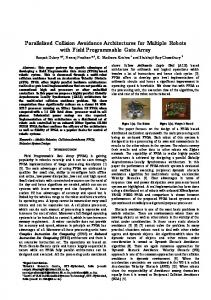
robot to move through centre of the obstacles. In order to simplify the problem, it assumes the robot and obstacles as circular objects. It also adds the robot’s dimensions into the obstacle dimensions for path calculations. For brevity in discussion, the nomenclature for gap mid-point determination is illustrated in Figure 1. Two obstacles in vicinity of the robot’s left and front beams are exemplified here. Let denote the gap centre angle (angle of mid-point between obstacles measured w.r.t. reference). and symbolize destination angle and final heading angle respectively. Robot Obstacle Destination Max. gap
θg θf θd
Bug-1 algorithm In Bug-1, after detecting an obstacle, the robot moves around the obstacle completely in order to find the point (leaving point) having minimum distance to destination. The robot restarts following the edge until it reaches to the computed leaving point and generates a new referenced path to destination.
Bug-2 algorithm In Bug-2, the robot stores the initial slope of reference path to destination. When an obstacle is encountered, the robot starts following edges of obstacle and continuously calculates slope of the line from its current position to the destination. The point where this slope becomes equal to the slope of reference path is considered as the leaving point.
Dist-Bug algorithm In the most improved Bug version, when the robot encounters an obstacle in its path, it starts following the edges of the obstacle calculating and simultaneously storing the distance from its current and next positions to destination. The leaving point is selected based on the condition that the distance of destination from its next position is greater than the corresponding distance from its current position.
Reference
Figure 1. Nomenclature of various angles
FGM involves three main computations; calculation of the gap array and finding the maximum gap, calculation of and finally determination of . During initiation, the method calculates the distance of each obstacle from the robot by using Pythagorean theorem. It then finds the maximum gap from the generated gap array. Based on the maximum gap, is determined using Cosine and Apollonius theorems. With the known angles and their weight coefficients, finally, is computed to steer the robot. In case of U/H shaped obstacles, FGM cannot find and thus because of being surrounded by a single boundary obstacle [7].
3. Novelty of Proposed Approach
FGM
Looking on the aforementioned algorithms, it is evident that there is no existing collision avoidance approach that encompasses following features in one strategy:
The concept of FGM is recently proposed by Sezer et al. in [7]. FGM avoids obstacles by finding the gap among them and allows the
Unlike to most of the reported algorithms, the proposed approach ensures collision avoidance from simple as well as critical
Studies in Informatics and Control, Vol. XX, No. X, Month Year
http://www.sic.ici.ro
3
shaped obstacles (e.g. U and H). After being stuck in such obstacles, IBA is used as a solution to avoid local minima. The proposed algorithm (IBA) plans the robot’s trajectory keeping in view clear path toward destination. The decision based on clear path in the proposed strategy also beneficiate to have a safer operation in the presence of multiple obstacles placed in close vicinity.
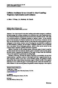
defined by the pixels. Three consecutive beams indicate the scanned region of 135° as illustrated in Figure 2. The front beam is representing the FOV of the robot from -22.5° to 22.5° while left and right beams correspond to view from -67.5° to -22.5° and 22.5° to 67.5° respectively. ft Le m a e B
The proposed approach incorporates the robot’s dimensions by defining a threshold distance between obstacles encountered. Unlike to unidirectional algorithms, the proposed approach replies on sensors with wide Field Of View (FOV) thus permitting bidirectional obstacle avoidance. The approach presented in this research offers comparatively lesser trajectory and hence reduces traversal time. No priori information or map of the environment is required since the decisions are based on current percepts. The proposed algorithms, owing to computationally inexpensive, can be implemented in real time using simple microcontrollers. The proposed approaches do not need defining sub-goals in maze-type environments.
4. Description of Approach (IFGM)
Proposed
The proposed approach is intended to improve the reported algorithms by addressing their inherent problems and limitations. An algorithm having comparatively more intelligence and efficiency that can avoid critical shaped (U and H for examples) obstacles is the goal of this research in addition to addressing local minima problem. The proposed approach, named as Intelligent Follow the Gap Method (IFGM), relies on Infrared (IR) sensor data for detecting obstacles. The sensor needs to be mounted on the robot in a way so as to give the robot Field Of View (FOV) of 135°. In a typical hardware platform, the sensor can be mounted on a stepper motor (restricted to rotate from -67.5° to 67.5°) while in a simulation environment (e.g. MATLAB), the beam of IR sensor is 4
http://www.sic.ici.ro
Front Beam
Righ t Beam
Figure 2. For IFGM, the robot FOV consists of three consecutive beams
During initialization, source and goal positions are provided to the robot to generate the shortest reference path. After path planning, the robot is commanded to function in move to goal behaviour and is steered on reference path until destination is reached or an obstacle is sensed. In case an obstacle is encountered, the control is switched to obstacle avoidance behaviour until obstacle is avoided. The path is then regenerated from the robot’s current position to destination. This path is considered as the updated reference path. The obstacle avoidance behaviour of the robot is based on the orientation of obstacles, which is taken by monitoring the position of beam. A distance vector is calculated with the help of sensed position of obstacle and the robot’s current position. In case of more than one obstacle, average clustered value is considered as the obstacle position for distance vector. The obstacle near to the robot is given higher priority. In a similar way as in FGM, an obstacle array is created, which indicates the position of obstacles in terms of (x,y) coordinates obtained by resolving distance vector into rectangular coordinates. Using this array, the gap (Euclidian distance) between every two consecutive obstacles is calculated. The coordinates of obstacles having maximum gap are stored to steer the robot from middle of obstacles, if the calculated maximum gap is greater than a certain threshold value ( ).
Studies in Informatics and Control, Vol. XX, No. X, Month Year
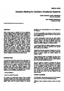
Choice of is a function of the robot’s dimensions. It must be greater than the robot’s operational radius (greater than the width of a squared shaped robot or radius of a cylindrical shaped robot). The distance of the robot to its nearest obstacle also needs to be taken into account to ensure safety in a maze-like environment. For this, another threshold distance is defined. This parameter depends on speed of the robot and is set to a higher value for a high speed robot. The functional flowchart of IFGM is illustrated in Figure 3. Start
distance of the robot to its nearest obstacle is greater than . Case-1: If the max. gap is greater than , then the orientation of midpoint, angle and direction are calculated from saved coordinate of obstacles, as described by (1) and (2). (1)
(2) where (
, ) are coordinates of mid-point, and are saved coordinates of obstacles.
Initialization
is computed using (3). Compute shortest distance to dest. Obs_flag = 0 Yes
No
Obstacle Detected
Obs_flag = = 1
Yes
No Move on planned path
Create array of sensed obstacles Calculate max. gap between obstacles
Destination reached ? No Yes Stop
obs. dist. > dobs max. gap > dth
where and are coordinates of current and destination positions respectively. Finally, as given by (4), is determined based on , from current position and their weight coefficients [7], which introduced goal oriented behaviour in the algorithm. The robot is then steered to .
Store the position of obstcles having max. gap Calculate distance of stored obstacles from the robot (obs. dist.)
No Move using IBA
Yes Move using FGM
(3)
Obs_flag = 1
Figure 3. Flowchart of IFGM
(4)
where and are the weight coefficients of gap and goal respectively.
Case-2: In case, the max. gap is less than or equal to , or obstacles are detected only in one side of the robot, obstacles are avoided using IBA.
Case-3:
N
The control of the robot is based on the thresholds and . After encountering the obstacles, if both conditions are true (refer to Figure 3), the robot is steered by FGM otherwise it is steered by IBA (discussed in next sub-section). After avoiding obstacles, the robot regenerates the reference path and follows it until reaches to the destination. To analyze the control behaviour in reference to , the most important cases are discussed below. It has been assumed here that the
If the robot is in obstacle avoidance behaviour and another obstacle is sensed having more impact than the first, it starts avoiding second obstacle instead of previous one. After successfully avoiding it, the robot resumes its behaviour from where it left and restarts avoiding first obstacle again if it still exists. It changes the behaviour to move to goal if first obstacle does not exist anymore or has been avoided. This is achieved by detecting and avoiding obstacles recursively using IBA. Recursive function in the proposed algorithm
Studies in Informatics and Control, Vol. XX, No. X, Month Year
http://www.sic.ici.ro
5
permits the robot to navigate through the critical shaped obstacles. In case of U shaped obstacle, after the robot gets stuck, it recursively turns in steps of 45° until it finds obstacle free path (on 180°). It then continues its motion in that direction, thus avoiding a U shaped obstacle. In case, source and destination points are enclosed in a H shaped obstacle, the robot uses the same concept described for U shaped obstacles to safely navigate without colliding the walls of H block. As shown in Figure 3, IFGM is based on the improved version of Bug i.e. Intelligent Bug Algorithm (IBA), which is detailed below:
IBA The fact that Dist-Bug algorithm is not a goaloriented algorithm [8], gave a clue to improve this algorithm by devising an approach to make it goal oriented and to account for the time taken by the robot to reach goal. Based on this, the proposed IBA improves overall behaviour of the robot and makes it possible to achieve the goal in comparatively less time by following short and smooth trajectory. In contrast with Bug family algorithms, bidirectional mechanism is introduced in IBA using the sensor’s configuration on the robot. The move to goal behaviour of IBA is similar to Bug family. However in obstacle avoidance behaviour, the robot continuously monitors the obstacles in the path toward destination during edge detection. The leaving point is selected based on free path instead of shorter distance toward destination. This condition, not introduced in Dist-Bug algorithm, offers distinguishing feature of goal orientation. At leaving point, when an obstacles-free path is sensed, the robot changes its behaviour to move to goal in order to generate new reference path (just like humans as they follow straight path after avoiding hurdles).
5. Simulation Results The effectiveness of the proposed algorithms (IBA and IFGM) has been demonstrated using simulation results. Their performance has been compared with the corresponding algorithms reported in the literature by considering various scenarios. These scenarios varied the number
6
http://www.sic.ici.ro
and shape of obstacles and their relative placement in the robot workspace. Two interesting scenarios are presented here consisting of simple obstacles and critical shaped (U and H shaped) obstacles.
Scenario 1: Avoiding simple obstacles Consider an environment having obstacles of simple but different shapes. The same environment is taken in all the cases to compare the performance of reported algorithms (Bug variants and FGM) and proposed algorithms (IBA and IFGM). The designed simulation platform resulted in the robot trajectories corresponding to these algorithms. In case, an obstacle is not sensed, the robot acts in same manner in all algorithms. Consider the situation when no obstacle lies in the robot’s path (Figure 4a). The algorithm generates a path from source to destination and starts following it until it reaches to the destination. The obstacles are now placed in the robot’s path. Figure 4b illustrates the behaviour of the robot in Bug-1 algorithm as it avoids both obstacles by edge detection and determines the leaving point finally finding its way to destination successfully. Figure 4c illustrates the trajectory of the robot using Bug2 algorithm, as the robot is following the initial reference path by comparing the slope at each step during obstacle avoidance. Figure 5a shows the performance of the robot in Dist-Bug algorithm, where the robot is following the edge of obstacle until it reaches to the leaving point having minimum distance to destination. Simulation result of the proposed IBA is shown in Figure 5b, the robot is following the edge until it finds the clear path towards the destination. Comparing the robot trajectories of Figure 5a and 5b confirms that proposed algorithm improves the Dist-Bug algorithm since the path covered by the IBA is smaller and smoother than Dist-Bug algorithm. Figure 5c and 5d presents the robot’s trajectories in case of FGM and IFGM algorithms respectively. Since the considered scenario consists of simple shaped objects and no critical shaped object is placed, so the results of FGM and IFGM are same. It is obvious from Figures 4 and 5, the trajectory covered by the robot based on IFGM/FGM is even smoothest and shortest as compared with the trajectories obtained using the mentioned algorithms.
Studies in Informatics and Control, Vol. XX, No. X, Month Year
(a)
(b)
(c)
Figure 4. Robot trajectories using (a) Any algorithm (b) Bug-1 algorithm (c) Bug-2 algorithm
(a)
(b)
(c)
(d)
Figure 5. Robot trajectories for performance comparison (Scenario 1) using (a) Dist-Bug algorithm (b) IBA (c) FGM algorithm (d) IFGM algorithm
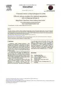
Distance-time graph 200 No obstacle Bug-1 Bug-2 Dist-bug IBA FGM IFGM
180 160
Distance to destination (ft)
The distance-time graph of the above mentioned algorithms giving the path cost is illustrated in Figure 6. The minimum distance from source to destination is 197ft, which is covered in 149sec when no obstacle lies in the path. Considering obstacles in the path, this time increases by a factor dictated by an algorithm efficiency. Dist-Bug takes 205sec where as the proposed IBA takes 184sec to reach the goal, which confirms the outstanding performance of IBA as compared to Bug algorithms. Finally, IFGM takes only 180sec to reach the destination. From this comparison, it can be seen that the IFGM/FGM takes least time and has a smoother trajectory than other. To compare the performance of FGM and IFGM algorithms, another scenario having critical shaped obstacles has been taken.
140 120 100 80 60 40 20 0
0
50
100
150
200
250
300
350
400
450
500
Time (sec)
Figure 6. Path cost as a function of time for performance comparison (Scenario 1)
In a special case of an environment having symmetric obstacles, the complexity of situation is increased since the robot may get
Studies in Informatics and Control, Vol. XX, No. X, Month Year
http://www.sic.ici.ro
7
between them. In case of Figure 7a and 7c this gap is greater than the defined threshold, so the robot avoids the obstacle using IFGM. Figure 7b and 7d shows the robot’s behaviour when distance between the obstacles is less than the threshold distance. The robot after calculating the distance between encountered obstacles avoids the obstacle using IBA since the computed distance is less than the defined threshold.
Environment 1
stuck into local minima. This condition is unavoidable for many algorithms (e.g. APF and VFH) because of nature of their control strategy. Consider three symmetrical obstacles placed in the path of the robot as shown in Figure 7. The robot plans the shortest path form initial to final position and starts following it until an obstacle is encountered. After sensing an obstacle, it starts avoiding it using IBA. While avoiding the first obstacle, it encounters another obstacle and starts calculating the gap
(b)
(c)
(d)
Environment 2
(a)
Figure 7. IFGM performance in symmetrical obstacles when (a)(c) Obstacles placed at a distance (b)(d) Obstacle placed nearby
Scenario 2: Avoiding critical shaped obstacles
FGM, APF is also unable to take decision in this critical scenario [8].
Consider a more complicated environment having U and H shaped obstacles as shown in Figure 8. Such a critical scenario highlights the novelty and can witness the improvement over the existing approaches since algorithms like FGM, APF, VFH etc fail here because of their local characteristics while algorithms like Bug variants suffer from slow speed. Figure 8a shows the trajectory of FGM algorithm. The robot generates the path from initial to final position and then starts following it. It finds the U shaped obstacle in its path and calculates the distance between sidewalls of U-block. Finally, the robot is steered towards centre of the obstacle since the calculated distance is greater the define threshold. At the centre of obstacle, the robot becomes unable to take any decision. This is the dead-end scenario for FGM and is considered as a local minimum [7]. Similar to
The proposed algorithm IFGM is efficient enough to tackle this critical case. The robot follows the reference path generated during initialization and encounters a U shaped obstacle. At first, when the robot senses the side walls of obstacle, it calculates the distance and steers inside using IFGM. After detecting the front wall, a recursive obstacle avoidance function is called which turns the robot about 45° and then 90° (if obstacle is not avoided) and so on in order to finally avoid it, as discussed in section 4 (case 3). The robot finds the clear path towards 180° and stats moving back. Simultaneously, it detects the side wall in 135° FOV and finds the clear path in respective direction after reaching to the end of wall. The robot avoids the wall by following its boundary from outside and completes the recursive function followed by regeneration of the
8
http://www.sic.ici.ro
Studies in Informatics and Control, Vol. XX, No. X, Month Year
reference path towards the destination in its move to goal behaviour. It now encounters the H shaped obstacle and avoids it by IFGM. The strategy to avoid H shaped obstacle is same as
that of coping U shaped. The overall performance of IFGM can be seen in Figure 8b.
(a)
(b)
Figure 8. Robot trajectories for performance comparison (Scenario 2) using (a) FGM algorithm (b) IFGM algorithm
The distance-time graph of the robot is depicted in Figure 9, which indicates the time taken by the robot to reach its destination using FGM and IFGM algorithms. Distance-time graph 200 FGM IFGM
180
Distance to destination (ft)
160 140 120 100 80 60 40 20 0
0
50
100
150
200
250
Time (sec)
Figure 9. Path cost as a function of time for performance comparison (Scenario 2)
6. Conclusion Two new approaches IBA and IFGM are presented in this paper for autonomous navigation of mobile robots. The proposed algorithm IBA follows the shorter and smoother trajectory and achieves the goal in lesser time as compared to reported Bug algorithms. IBA is a goal-oriented algorithm with improved characteristics, making it an efficient approach to prove its convergence with relatively shorter and smoother trajectory in contrast with Dist-Bug algorithm. The second proposed algorithm IFGM offers convergence by calling a recursive function. It over-performs for safe and autonomous navigation and is computationally simpler than
the reported FGM. The computational approach adopted for the orientation of obstacles is very easy and can be achieved by physical mechanism (IR sensor and stepper motor). The proposed approaches do not suffer from local minima and can together easily tackle U and H shaped obstacles, which are the dead-end scenarios for APF, FGM, VFH and other reported algorithms for obstacle avoidance. The proposed algorithms do not require prior information of environment as needed by NHNA since decisions are based only on current percepts captured by the sensor. Furthermore, it does not have high requirements of external memory and a sophisticated processor like beagle board, Raspberry PI or FPGA. A commonly available micro controller is enough for computations involved. A single long range IR, when mounted on a stepper motor increases the robot FOV (up to 135°) making the algorithms wellsuited for dynamic environments, since the requirement on the numbers of required sensors is decreased. The coordinates of source and destination and information about current position of the robot can be obtained from Odometry or GPS. In addition to robotics, IFGM can find potential in navigation of ships, autopilot aircrafts, intelligent wheelchair and other applications requiring autonomy.
Acknowledgements This research has been funded by National Information and Communication Technology (ICT) R & D Fund under agreement no. NICTRRFD/NGIRI/2012-13/corsp/3 Sr. 5.
Studies in Informatics and Control, Vol. XX, No. X, Month Year
http://www.sic.ici.ro
9
2090-4304, vol. 3 no. 4, pp.10271036, 2013.
REFERENCES 1.
IQBAL, J., ISLAM, R., KHAN, H., Modeling and Analysis of a 6 DOF Robotic Arm Manipulator, Canadian Journal on Electrical and Electronics Engineering, vol. 3, no. 6, 2012, pp. 300-306.
2.
IQBAL, J., NABI, R., KHAN, A.A., KHAN, H., A Novel Track-Drive Mobile Robotic Framework for Conducting Projects on Robotics and Control Systems. Life Sci J, ISSN 1097-8135, vol. 10 (3), pp.130137, 2013.
3.
KAREEM JARADAT, M. A., ALROUSAN, M., QUADAN, L., Reinforcement Based Mobile Robot Navigation in Dynamic Environment, Robotics and Computer-Integrated Manufacturing, vol. 27, no. 1, 2011, pp. 135–149.
4.
CARRETERO, J. A., EBRAHIMI, I., BOUDREAU, R., Overall Motion Planning for Kinematically Redundant Parallel Manipulators, J. Mechanisms Robotics, vol. 4, no. 2, 2012
5.
BRASSAI, S.T., IANTOVICS, B., ENACHESCU, C., Optimization of Robotic Mobile Agent Navigation, Studies in Informatics and Control, ISSN 1220-1766, vol. 21 (4), pp. 403-412, 2012.
6.
7.
8.
10
BABINEC, A., DEKAN, M., DUCHOŇ, F., VITKO, A., Modifications of VFH Navigation Methods for Mobile Robots, Procedia Engineering, vol. 48, 2012, pp. 10-14. SEZER, V., GOKASAN, M., A Novel Obstacle Avoidance Algorithm: Follow the Gap Method, Robotics and Autonomous Systems, vol. 60, no. 9, 2012, pp. 1123-1134. ZOHAIB, M., PASHA, M., RIAZ, R. A., JAVAID, N., ILAHI, M., KHAN, R. D., Control Strategies for Mobile Robot With Obstacle Avoidance, Journal of Basic and Applied Scientific Research, ISSN http://www.sic.ici.ro
9.
ZHU, Y., ZHANG, T., SONG, J., LI, X., A New Hybrid Navigation Algorithm for Mobile Robots in Environments with Incomplete Knowledge, Knowledge-Based Systems vol. 27, 2012, pp. 302–313.
10.
SGORBISSA, A., ZACCARIA, R., Planning and Obstacle Avoidance in Mobile Robotics, Robotics and Autonomous Systems, vol. 60, no. 4, 2012, pp. 628-638.
11.
QUINLAN, S., KHATIB, O. Elastic Bands: Connecting Path Planning and Control, IEEE International Conference on Robotics and Automation (ICRA), 1993, pp. 802– 807. SUSNEA, I., FILIPESCU, A., VASILIU, G., COMAN, G., A. RADASCHIN, A., The Bubble Rebound Obstacle Avoidance Algorithm for Mobile Robots, 8th IEEE International Conference on Control and Automation, 2010, pp. 540–545. PHILIPPSEN, R., SIEGWART, R., Smooth and Efficient Obstacle Avoidance for a Tour Guide Robot, International Conference on Robotics and Automation (ICRA) , 2003, pp. 446-451. ZHU, Y., ZHANG, T., SONG, J., LI, X., A New Bug-type Navigation Algorithm Considering Practical Implementation Issues for Mobile Robots, IEEE International Conference on Robotics and Biomimetics, 2010, pp. 531-536.
12.
13.
14.
15.
YUFKA, A., PARLAKTUNA, O., Performance Comparison of Bug Algorithms for Mobile Robots, Proceedings of the 5th International Advanced Technologies Symposium, Turkey. 2009.
Studies in Informatics and Control, Vol. XX, No. X, Month Year