Hindawi Publishing Corporation Journal of Applied Mathematics Volume 2014, Article ID 659805, 13 pages http://dx.doi.org/10.1155/2014/659805
Research Article An Improved Fast Flocking Algorithm with Obstacle Avoidance for Multiagent Dynamic Systems Jialiang Wang,1 Hai Zhao,1 Yuanguo Bi,1 Shiliang Shao,2 Qian Liu,1 Xingchi Chen,1 Ruofan Zeng,1 Yu Wang,1 and Le Ha1 1 2
College of Information Science & Engineering, Northeastern University, Shenyang 110819, China Shenyang Institute of Automation, Chinese Academy of Sciences, Shenyang 110016, China
Correspondence should be addressed to Yuanguo Bi;
[email protected] Received 8 October 2013; Revised 12 May 2014; Accepted 24 May 2014; Published 24 June 2014 Academic Editor: Jin L. Kuang Copyright © 2014 Jialiang Wang et al. This is an open access article distributed under the Creative Commons Attribution License, which permits unrestricted use, distribution, and reproduction in any medium, provided the original work is properly cited. Flocking behavior is a common phenomenon in nature, such as flocks of birds and groups of fish. In order to make the agents effectively avoid obstacles and fast form flocking towards the direction of destination point, this paper proposes a fast multiagent obstacle avoidance (FMOA) algorithm. FMOA is illustrated based on the status of whether the flocking has formed. If flocking has not formed, agents should avoid the obstacles toward the direction of target. If otherwise, these agents have reached the state of lattice and then these agents only need to avoid the obstacles and ignore the direction of target. The experimental results show that the proposed FMOA algorithm has better performance in terms of flocking path length. Furthermore, the proposed FMOA algorithm is applied to the formation flying of quad-rotor helicopters. Compared with other technologies to perform the localization of quad-rotor helicopter, this paper innovatively constructs a smart environment by deploying some wireless sensor network (WSN) nodes using the proposed localization algorithm. Finally, the proposed FMOA algorithm is used to conduct the formation flying of these quad-rotor helicopters in the smart environment.
1. Introduction Flocking is the behavior exhibited when a group of birds, called a flock, are foraging or in flight. There are similar behaviors such as the shoaling behavior of fish, the swarming behavior of insects, and the herd behavior of land animals [1]. Reynolds [2] firstly introduced three rules including flocking centering, obstacle avoidance, and velocity matching to imitate flocking by computer simulations. In [3, 4], Reynolds further explains the three rules. Toner and Tu [5] and Shimoyama et al. [6] conduct researches about multiagent flocking. Toner adopts a continuous model to analyze multiagent flocking. Shimoyama et al. propose to describe behavior of multiagents based on particle system and use function rules of overall perception to consider
the flocking of multiagent. Mogilner and Edelstein-Keshet [7, 8] use a continuous model to research the flocking of multiagent, and they consider the practical sensing problems. Jadbabaie et al. [9] conduct researches on the flocking behavior of multiagent based on the rule of the nearest agent and verify that the agents tend to move with the same direction under the assumption that all agents can detect each other. Quadrotor helicopters have been widely used nowadays due to their unique advantages. Flocking has also been considered as an approach to control the behavior of unmanned air vehicles (UAVs). Flocking is a common technology in screensavers and has been successfully used in animations. Flocking has been widely used in many films [10] to generate crowding. Tim Burton’s Batman Returns (1992) features flocking bats, and Disney’s The Lion King (1994)
2
Journal of Applied Mathematics 𝛾
named (𝛼, 𝛼), (𝛼, 𝛽), and (𝛼, 𝛾), respectively, and 𝑢𝑖 is also the item of feedback control. The calculation of the three input parameters is given by
d
𝑢𝑖𝛼 = 𝑐1𝛼 ∑ 𝜑𝛼 (𝑞𝑗 − 𝑞𝑖 𝜎 ) 𝑛𝑖,𝑗 + 𝑐2𝛼 ∑ 𝑎𝑖𝑗 (𝑞) (𝑝𝑗 − 𝑝𝑖 ) , 𝑗∈𝑁𝑖𝛼
𝑗∈𝑁𝑖𝛼
𝛽 𝛽 𝑢𝑖 = 𝑐1 ∑ 𝜑𝛽 (𝑞̂𝑖,𝑘 − 𝑞𝑖 𝜎 ) 𝑛̂𝑖,𝑘 𝛽
𝑗∈𝑁𝑖
𝛽 + 𝑐2 ∑ 𝑏𝑖,𝑘 (𝑞) (𝑝̂𝑖,𝑘 − 𝑝𝑖 ) , 𝛽
𝑗∈𝑁𝑖 𝛾
𝛾
𝛾
𝑢𝑖 = −𝑐1 𝜎1 (𝑞𝑖 − 𝑞𝛾 ) − 𝑐2 (𝑝𝑖 − 𝑝𝑟 ) , (2) Figure 1: Architecture of lattice.
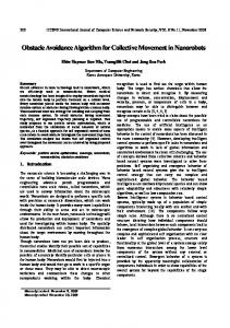
includes a wildebeest stampede. Flocking behavior has been used for other interesting applications. For example, it has been applied to Internet multichannel radio stations [11], information visualization [12], and optimization tasks [13]. Lattice graph is used in order to describe the relationship between different agents. For multiagent dynamical systems, if the configurations of agents satisfy the constraint that ‖𝑞𝑗 − 𝑞𝑖 ‖ = 𝑑, ∀𝑖, 𝑗 ∈ 𝑁𝑓 , where 𝑞𝑗 and 𝑞𝑖 represent the positions of agents 𝑗 and 𝑖, respectively, and 𝑁𝑓 denotes the set of all of the agents, these agents form a lattice as shown in Figure 1(a); then, 𝑑 is the goal distance (the length of side for the lattice). However, if the configurations of agents satisfy the constraint that −𝛿 ≤ ‖𝑞𝑗 −𝑞𝑖 ‖−𝑑 ≤ 𝛿, ∀𝑖, 𝑗 ∈ 𝑁𝑓 , then these agents form a quasilattice due to the movements of the agents. To form a lattice is the ideal status for the multiagent dynamical systems [2].
where 𝜎1 (𝑧) = 𝑧/√1 + ‖𝑧‖2 , 𝑐𝜂] is a positive constant, and 𝜂 = 1, 2, V = 𝛼, 𝛽, 𝛾. (𝑞𝑟 , 𝑝𝑟 ) means the position and velocity of 𝛾 agent, respectively. Vectors 𝑛𝑖,𝑗 and 𝑛̂𝑖,𝑘 are the direction vectors used to describe the relation of interaction for these agents, and they are given by
𝑛𝑖𝑗 =
𝑞𝑗 − 𝑞𝑖 2 √ 1 + 𝜀𝑞𝑗 − 𝑞𝑖
𝛽
𝛾
𝑢𝑖 = 𝑢𝑖𝛼 + 𝑢𝑖 + 𝑢𝑖 ,
(1)
where 𝛼, 𝛽, and 𝛾 represent three different agents and 𝛽 𝛾 𝑢𝑖 , and 𝑢𝑖 are the interaction mechanisms for the agent set
𝑞̂𝑖,𝑘 − 𝑞𝑖 . √1 + 𝜀𝑞̂𝑖,𝑘 − 𝑞𝑖 2 (3)
𝑞̂𝑖,𝑘 = 𝜇𝑞𝑖 + (1 − 𝜇) 𝑦𝑘 , 𝑝̂𝑖,𝑘 = 𝜇𝑃𝑝𝑖 ,
(4)
where 𝜇 = 𝑅𝑘 /‖𝑞𝑖 − 𝑦𝑘 ‖, 𝑎𝑘 = (𝑞𝑖 − 𝑦𝑘 )/‖𝑞𝑖 − 𝑦𝑘 ‖, and 𝑃 = 𝐼 − 𝑎𝑘 𝑎𝑘𝑇 . If the interaction mechanism between the two agent sets named (𝛼, 𝛼) and (𝛼, 𝛾) is fixed. Analyzing the interaction mechanism of (𝛼, 𝛽) agent, there are two parts for the mutual effect; the first one is repulsive interaction between 𝛽 agent and 𝛼 agent, and the second part is the velocity matching between them. The two parts exist all the time under the condition of 𝛽 agent entering the perception region of 𝛼 agent, which means that the neighbor condition of 𝛼 agent 𝛽 𝑞𝑖,𝑘 − 𝑞𝑖 ‖ < 𝑟 } is met. Besides, obstacle that 𝑁𝑖 = {𝑗 ∈ V𝛽 : ‖̂ 𝛽
𝑢𝑖𝛼 ,
𝑛̂𝑖,𝑘 =
Supposing an obstacle 𝑂𝑘 whose radius and center are 𝑅𝑘 and 𝑦𝑘 , respectively, and that there is an 𝛼 agent whose status is (𝑞𝑖 , 𝑝𝑖 ), then the position 𝑞̂𝑖,𝑘 and the velocity 𝑝̂𝑖,𝑘 of 𝛽 spherical agent ((𝑖, 𝑘) ∈ ]𝛼 × ]𝛽 ) are, respectively, defined by
2. Olfati-Saber Algorithm of Obstacle Avoidance for Multiagent Dynamical System Olfati-Saber proposed an algorithm of obstacle avoidance [14]. In this algorithm, obstacle is regarded as a moving agent, and system merges this velocity and the velocity of that agent entering the region of obstacle and then regards the merged velocity as next-time velocity for the agent. The magnitude of velocity, but not its direction, is considered while merging velocity. Besides, obstacle is still regarded as one agent while it is moving away from the obstacle, so this will disturb the behavior of the agent and even the process of obstacle avoidance for these agents. In the algorithm, the system input is given by
,
𝛽
the value of 𝑐1 and 𝑐2 does not change all the time. After analyzing the existing algorithm, we know that the algorithm has the following flaws.
Journal of Applied Mathematics
3
(a) It only judges the distance of 𝛼 agent and obstacle. While the distance is smaller than the distance perception, then the system will execute the process of obstacle avoidance, but without considering the velocity direction of 𝛼 agent, which means that the velocity direction of 𝛼 agent does not move toward the obstacle; under this case, if 𝛼 agent can detect the 𝛽 obstacle, the factor of 𝑐2 ∑𝑗∈𝑁𝛽 𝑏𝑖,𝑘 (𝑞)(𝑝̂𝑖,𝑘 − 𝑝𝑖 ) while 𝛽
yk
ddan
𝑖
calculating the 𝑢𝑖 will block the move path while 𝛼 agent is moving away from obstacle. (b) It only obtains the velocity matching between 𝛼 agent and 𝛽 agent, which means that the system aims to change the velocity direction of 𝛼 agent, till it tends to the same with 𝛽 agent; thus, the final velocity direction of 𝛼 agent is uncertain. So this is not beneficial for the form of flocking and access to target point. The major contribution of this paper is to propose an improved algorithm for obstacle avoidance, which aims to make the agents fast form flocking and approach the destination point; at the meantime, all agents can effectively avoid the obstacles. In addition, this paper innovatively constructs a smart environment to implement the localization of quadrotor helicopters, and the proposed FMOA algorithm is used to conduct the formation flying of quadrotor helicopters in the smart environment.
3. Fast Multiagent Obstacle Avoidance (FMOA) Algorithm The proposed algorithm is considered under the status of whether the flocking has formed. If there exists at least one agent having the same velocity with 𝛼 agent and the distance between them reaches the given value 𝑑, then it means that the flocking has formed. If the action range of 𝛼 agents is 𝑟, then the dangerous radius of an obstacle is 𝑑dan = 𝑅𝑘 + 𝑟 safe, where 𝑅𝑘 denotes the radius of obstacle and 𝑟 safe represents the predefined safe region of obstacle. Besides, using 𝑑𝑞 denotes the vector between 𝛼 agent and the center of obstacle as Figure 2 shows, and the tangent vector between 𝛼 agent and dangerous region of obstacle is defined as 𝑑𝑡1 and 𝑑𝑡2 , respectively. After agents detect the dangerous region of obstacle (while 𝑑 ≤ 𝑟), the system judges the direction of its velocity; if it moves within the region of obstacle (while det[𝑑𝑡1 , 𝑝𝑖 ] < 0 ∧ det[𝑑𝑡2 , 𝑝𝑖 ] > 0), the system will execute the process of obstacle avoidance. Otherwise, no obstacle exists. While 𝛼 agent enters the dangerous region of obstacle, the system regards the obstacle as 𝛽 agent; the magnitude and direction of its velocity for 𝛼 agent are discussed by the status of whether flocking has formed. System can judge whether 𝛼 agent enters the dangerous region of 𝛽 agent by calculating the value of det[𝑑𝑡1 , 𝑝𝑖 ], det[𝑑𝑡2 , 𝑝𝑖 ], and det[𝑑𝑞 , 𝑝], which are defined by
𝛽 dt1 dq dt2 (qi , pi )
𝛼
Figure 2: The description of agent and dangerous area.
𝑑 𝑝 det [𝑑𝑞 , 𝑝] = det [ 𝑥 𝑥 ] = 𝑑𝑥 𝑝𝑦 − 𝑑𝑦 𝑝𝑥 𝑑𝑦 𝑝𝑦 (5)
𝑝 = [𝑑𝑥 , 𝑑𝑦 ] [ 𝑦 ] , −𝑝𝑥 𝑝
𝑝
where [𝑑𝑥 , 𝑑𝑦 ] [ −𝑝𝑦𝑥 ] = 𝑑𝑞 𝑇; thus, 𝑇 = [ −𝑝𝑦𝑥 ]. So the above judgment can be simplified to judge its value. If vector 𝑑𝑞 𝑇 ≥ 0, it means that the velocity vector is above the median vector as Figure 3(a) shows; oppositely, if vector 𝑑𝑞 𝑇 < 0, it represents that the velocity vector is under the median vector as Figure 3(b) shows. 3.1. Flocking Has Not Formed. The target point 𝛾 is the final goal for 𝛼 agent. So, while agents avoid obstacles, the target point 𝛾 is the guided direction for these agents. (a) While 𝛾 agent is located in the region as Figure 4(a) shows, then the velocity direction of 𝛼 agent should be altered to the tangential direction of obstacle as 𝑝𝛽1 , which makes it avoid obstacle with the least deviation:
𝑝𝛼1
𝑝𝑖 𝜎 ⋅ (𝑞𝑖 − 𝑞𝛾 ) { { { , { { { (𝑞𝑖 − 𝑞𝛾 )𝜎 { { { { {𝑑 ≤ 𝑟} ∩ {det [𝑑𝑡1 , 𝑝𝑖 ] < 0 ∧ det [𝑑𝑞 , 𝑝𝑖 ] { { { { { > 0 ∧ det [𝑑𝑡1 , 𝑑𝛾 ] ≥ 0} = { { 𝑝 ⋅ (𝑞 − 𝑞 ) { 𝑖 𝜎 𝑖 𝛾 { { , { { { (𝑞 − 𝑞 ) 𝑖 { 𝛾 𝜎 { { { { {𝑑 ≤ 𝑟} ∩ {det [𝑑𝑞 , 𝑝𝑖 ] < 0 ∧ det [𝑑𝑡2 , 𝑝𝑖 ] { { > 0 ∧ det [𝑑𝑡2 , 𝑑𝛾 ] ≤ 0} . { (6)
4
Journal of Applied Mathematics
P
𝛽 agent
𝛽 agent
dq
T
P
dq q 𝛼 agent
𝛼 agent q
T (a)
(b)
Figure 3: The relative position relationship between agent and obstacle.
Dangerous area
Dangerous area
𝛽 agent
𝛽 agent
𝛾 agent
𝛾 agent
q
q 𝛾 agent
𝛼 agent
𝛾 agent
𝛼 agent
(a)
(b)
𝛾 agent
𝛾 agent
Dangerous area
Dangerous area
𝛽 agent
𝛽 agent
q
q 𝛼 agent
𝛼 agent
(c)
(d)
Figure 4: Different conditions between agents while flocking has not formed.
Journal of Applied Mathematics
5 Beginning
Neighbors No with the same velocity and Yes distance between them is d? Agent moving toward obstacle?
No Agent moving toward obstacle?
Yes
Yes
Target agent in the region of two tangent lines formed by agent and obstacle?
Target agent Yes in the region of two tangent lines formed by agent and obstacle?
Change velocity of agent to P𝛼2
Yes
No
No Change velocity of agent to P𝛼1
No
Keep current velocity
Change velocity of agent to P𝛼3
Change velocity of agent to P𝛼4
Keep current velocity
End
Figure 5: The workflow of FMOA algorithm.
(b) While 𝛾 agent is located in the region as Figure 4(b) shows, then the velocity direction of 𝛼 agent should be altered to the target point. In this case, system does not change the velocity direction of 𝛼 agent, because the obstacle will not affect the movement of 𝛼 agent. (c) While 𝛾 agent is located in the region as Figure 4(c) shows, then the velocity direction of 𝛼 agent should be altered to the tangential direction. The velocity of 𝛼 agent is given by
𝑝𝛼2
𝑝𝑖 𝜎 ⋅ 𝑑𝑡1 { { , { { 𝑑𝑡1 𝜎 { { { { {𝑑 ≤ 𝑟} ∩ {det [𝑑𝑡1 , 𝑝𝑖 ] < 0 ∧ det [𝑑𝑞 , 𝑝𝑖 ] { { { { { > 0 ∧ det [𝑑𝑡1 , 𝑑𝛾 ] { { { { { < 0 ∧ det [𝑑𝑡2 , 𝑑𝛾 ] > 0} = { 𝑝 ⋅ 𝑑 { 𝑖 𝜎 𝑡2 { { { , { { 𝑑𝑡2 𝜎 { { { { {𝑑 ≤ 𝑟} ∩ {det [𝑑𝑞 , 𝑝𝑖 ] < 0 ∧ det [𝑑𝑡2 , 𝑝𝑖 ] { { { { { > 0 ∧ det [𝑑𝑡1 , 𝑑𝛾 ] { { < 0 ∧ det [𝑑𝑡2 , 𝑑𝛾 ] > 0} . {
𝑝𝛼3
𝑝𝑖 𝜎 ⋅ 𝑑𝑡1 { { { , { { { 𝑑𝑡1 𝜎 { { { {𝑑 ≤ 𝑟} ∩ {det [𝑑𝑡1 , 𝑝𝑖 ] > 0 ∧ det [𝑑𝑡1 , 𝑑𝛾 ] { { { { { < 0 ∧ det [𝑑𝑡2 , 𝑑𝛾 ] > 0} = { 𝑝 ⋅ 𝑑 { 𝑖 𝑡2 { 𝜎 { { , { { 𝑑𝑡2 𝜎 { { { { {𝑑 ≤ 𝑟} ∩ {det [𝑑𝑡2 , 𝑝𝑖 ] < 0 ∧ det [𝑑𝑡1 , 𝑑𝛾 ] { { { < 0 ∧ det [𝑑𝑡2 , 𝑑𝛾 ] > 0} . {
(8)
3.2. Flocking Has Formed. After flocking is formed, 𝛼 agent has the same velocity with its neighbors, so if it moves toward the direction of obstacle, its next-time velocity should be changed to the tangential direction of the obstacle. The velocity of 𝛼 agent is given by
(7) (d) While 𝛾 agent is located in the region as Figure 4(d) shows, then the velocity direction of 𝛼 agent should be altered to the tangential direction. The velocity of 𝛼 agent is given by
𝑝𝛼4
𝑝𝑖 𝜎 ⋅ 𝑑𝑡1 { { { , { { 𝑑 { { 𝑡1 𝜎 { { {𝑑 ≤ 𝑟} ∩ {det [𝑑𝑡1 , 𝑝𝑖 ] < 0 ∧ det [𝑑𝑞 , 𝑝𝑖 ] > 0} = { { 𝑝𝑖 𝜎 ⋅ 𝑑𝑡2 { { { , { { 𝑑 { { 𝑡2 𝜎 { {𝑑 ≤ 𝑟} ∩ {det [𝑑𝑞 , 𝑝𝑖 ] < 0 ∧ det [𝑑𝑡2 , 𝑝𝑖 ] > 0} . (9)
6
Journal of Applied Mathematics
180 160 140 120 y
100 80 60 40 20 0 0
20 40 60 80 100 120 140 160 180 x
180 160 140 120 100 y 80 60 40 20 0 −20 −20 0
20 40 60 80 100 120 140 160 180 x
(a)
180 160 140 120 100 y 80 60 40 20 0 −20 −20 0
(b)
180 160 140 120 y
100 80 60 40 20 0 −20 0
20 40 60 80 100 120 140 160 180
20 40 60 80 100 120 140 160 180
x
x
(c)
(d)
180
180
160
160
140
140
120 y
100
y
80 60
100 80
40
60
20 0
120
40 0
40
20 40 60 80 100 120 140 160 180 x
60
80
100
120
140
160
180
x
(e)
(f)
170
170 160 150 140 130 y 120 110 100 90 80 70
160 150 140 y 130 120 110 100 90 70 80 90 100 110 120 130 140 150 160 170 x
90
(g)
100 110 120 130 140 150 160 170 x (h)
Figure 6: Continued.
Journal of Applied Mathematics
y
7
170
170
160
160
150
150
140
140
130
y
120
130 120
110
110
100
100
90
90 80
80 90
90
100 110 120 130 140 150 160 170 x
100 110 120 130 140 150 160 170 x
(i)
(j) 190
180 170
180
160
170
150
160
y 140
y 150
130
140
120
130
110
120
100
110
90 100 110 120 130 140 150 160 170 180 x
80
100
120
(k)
180
200
(l)
200
200
180
180
170 160
y 160
150
140
140 130
120
120 110
160
220
190
y
140 x
100 80
100
120
140
160
180
200
80
220
100
120
140
160
180
200
220
x
x (m)
(n)
260
250
240 220 200
200
y
y
180 160
150
140 120 100 80
100 120 140 160 180 200 220 240
100 80 100 120 140 160 180 200 220 240 260 x
x (o)
(p)
Figure 6: Continued.
8
Journal of Applied Mathematics 280
350
260 300
240 220 y
250
200
y
180
200
160 140
150
120 100
100 80 100 120 140 160 180 200 220 240 260 280
50
100
150
200 x
x (q)
250
300
350
(r)
Figure 6: Simulation process of the proposed FMOA algorithm with avoiding obstacles.
1050
950 900 850 800
0 1 2 3 4 5 6 7 8 9 10 11 12 13 14 15 16 17 18 19 20 21 22 23 24 25 26 27 28 29 30 Experiment ID Olfati-Saber algorithm FMOA algorithm
Figure 7: Experimental results about flocking path.
nd Se Video transmitter kit
es m fra C eo P id ote gv m in re
vi C o de l l e o ct fra in m g es
Flocking path (m)
1000
to Image processing in remote PC
ca
lc u
Co lle
in ga nd
r so en gs in a lat dat
ArduCopter
ct
to ata g d PC n i d te Sen remo
Calculating the information of navigation and obstacle avoidance
ht ig to g fl s r in nd te nd ma op Se om duC c Ar
ht flig ds g din man Sencom
Radio telemetry kit
Figure 8: Workflow of the whole quadrotor helicopter system.
Journal of Applied Mathematics If it does not move toward the direction of obstacle, then it should just follow its neighbors, because the obstacle will not affect the movement of the 𝛼 agent at all. System continuously adjusts the movement of agents according to the following conditions: whether there exist the neighbors with the same velocity and the distance between the agent and its neighbor is 𝑑, whether the direction of moving agent is toward the obstacle, and whether target agent is located in the region of two tangent lines formed by agent and obstacle. Then, system will adjust the velocity of agents according to the above different cases, and the whole algorithm can be described as Figure 5 shows.
4. Simulation Experiment Test In the experiments, Matlab 7.0 is used as the simulation software. System randomly generates 100 agents in the given region as Figure 6(a) shows. The red circle represents the obstacles, and the smaller black circles represent the agents. Besides, the execution parameters of communication distance, lattice length, and safe distance of obstacle are set as 8.8 m, 7 m, and 2 m separately. For each agent, its arrow describes the direction of the velocity, and the length of the arrow means the magnitude of the velocity. At any certain time, if agents form lattice, then blue lines are added between these agents. These following pictures show the simulation process of FMOA flocking with avoiding obstacles for these agents. As Figure 6 shows, we can know that agents can effectively avoid obstacles and form flocking toward the direction of destination point. Besides, in order to test the performance of the proposed FMOA algorithm, we tested its flocking path and compared it with Olfati-Saber algorithm. Flocking path length means the total length of paths that all of the agents move from the initial status to the final flocking status after avoiding all obstacles. For the flocking path, the less its value is, the less time the agents spend to reach the destination point with the proposed FMOA algorithm, since these agents have the same magnitude of velocity. In addition, the time complexity of the proposed FMOA algorithm is still 𝑂(𝑛2 ), which is the same as that of Olfati-Saber algorithm. These experiments are executed with different obstacles and parameter settings. As the experiment results of Figure 7 show, the proposed FMOA algorithm has better efficiency than Olfati-Saber algorithm.
5. The Application of the Proposed FMOA Algorithm Nowadays, there are many researchers focusing on the research about localization of quadrotor helicopters. Compared with other solutions used to locate the positions of quadrotor helicopters by GPS, laser finder range, and ultrawideband, this paper innovatively constructed smart indoor environment by deploying WSN nodes.
9 5.1. Current Techniques about Localization of Quadrotor Helicopters (a) Laser Range Finder. Abraham Bachrach and others in MIT focus on the research on embedding laser range finder to the hardware platform of quadrotor helicopter, so as to conduct localization of the quadrotor helicopter and explore unknown area. For example, one of their publications [15] focused on the implementation of exploring unknown environment by embedding laser range finder to the quadrotor helicopter. (b) Ultra-Wideband (UWB) Signal. In order to solve the localization of quadrotor helicopter in indoor environment, Damien B and others in MIT propose to deploy beacons in the test environment. One of their papers [16] targets the algorithm of using some known beacons (at least three beacons are needed) to accurately locate the positions of unknown agents in the indoor environment. (c) Global Position System (GPS). Ruijie He and others in MIT have conducted research of embedding GPS devices into the hardware platform of quadrotor helicopter, so as to adopt the quadrotor helicopter to implement object tracking and path planning, and so forth. One of their publications [17] focuses on the design of light-weight quadrotor helicopter and implementation of tracking objects. In fact, GPS can work well outdoors, but in the indoor environment, it usually cannot be used to implement the localization. 5.2. The Construction of Smart Environment. In order to locate the position of the quadrotor helicopter in indoor environment, wireless sensor network (WSN) nodes are deployed in the smart environment. Accordingly, the wireless communication is enabled for each quadrotor helicopter so as to form a WSN node, so quadrotor helicopters can communicate with the WSN nodes deployed in the smart environment. Based on the analysis of localization error [18], this paper proposes a fast localization algorithm as follows. Step 1. Calculate the distance between two nodes (including all quadrotor helicopters). Step 2. Unknown nodes send broadcast packet periodically, and each packet includes the information format {ID, 𝑇𝑠 , (𝑎, 𝑏, 𝑐)}, where ID is the identification of the unknown node, 𝑇𝑠 is the time when the reference node sends the packet, and (𝑎, 𝑏, 𝑐) is the coordinate value of an unknown node. Step 3. Reference node 𝑖 receives the localization packet and then calculates the distance 𝐿 𝑖 between certain reference node 𝑖 and the unknown node.
10 4 Step 4. For these 𝑁 packets, according to the 𝐶𝑁 set, the system performs the following judgments repeatedly.
(a) Use cos 𝑎𝑖,𝑗 = (𝐿2𝑖 + 𝐿2𝑗 − 𝐿2𝑖𝑗 )/2𝐿 𝑖 𝐿 𝑗 to calculate the included angle formed by the unknown node and any two reference nodes (for the set composed of the four ones), where 𝐿 𝑖 and 𝐿 𝑗 represent the distances between the unknown node and the two reference nodes, respectively, and 𝐿 𝑖𝑗 is the distance between the two reference nodes. Choose the reference nodes whose six included angles are all within the range [70.5∘ − 𝜑, 70.5∘ + 𝜑] and store them in the set 𝐻; then, 𝐾 = 𝐾 + 1 (the initial value of 𝐾 is 0), and return to Step 4; otherwise, go to the next step. (b) While both of the following conditions are satisfied, then 𝐾 = 𝐾 + 1. (1) The included angle formed by any two reference nodes (for the set composed of the three reference nodes) and the unknown node (vertex of the included angle) is within the range [𝜋/3 − 𝜃, 𝜋/3 + 𝜃], where 𝜃 is the angle threshold. (2) The line connected by the fourth reference node and the unknown node and the plane formed by the other three reference nodes will form an included angle. When the included angle is within the range [𝜋/2 − 𝜔, 𝜋/2 + 𝜔], where 𝜔 is the angle threshold, then return to Step 4; otherwise, go to the next step. Step 5. Finally, calculate all of the elements in the set 𝐻, and obtain their average value 𝐻avg . Then, 𝐻avg is the estimated position of the unknown node. 5.3. The Proposed Algorithm Used in Formation Flying of Quadrotor Helicopters. In order to apply the proposed algorithm (FMOA), ArduCopters are used as the quadrotor helicopter platform in the constructed smart indoor environment. Real-time data and images are transmitted between ArduCopters and remote PC. Video frames are sent to remote PC by Video Transmitter Kit; accordingly, the process (such as flight attitude, navigation, and obstacles avoidance) is handled in remote PC [19–26], and then flight commands are sent to ArduCopters through Radio Telemetry Kit [27]. The workflow of the whole quadrotor helicopter system is shown as in Figure 8. (a) Quadrotor Helicopters in the Same Height. From the analysis of Figure 9(a), the values of destination points (𝑥1 , 𝑦1 ), (𝑥2 , 𝑦2 ), (𝑥3 , 𝑦3 ), (𝑥4 , 𝑦4 ), (𝑥5 , 𝑦5 ), and (𝑥6 , 𝑦6 ) are (0, 𝐿) (−𝐿 ⋅ tan 𝛽, 0), (𝐿 ⋅ tan 𝛽, 0), (−2𝐿 ⋅ tan 𝛽, 0), (0, −𝐿), and (2𝐿 ⋅ tan 𝛽, 0), respectively. These values are very important for each helicopter flying from the current position to these destination positions, respectively. There are totally 23 WSN nodes placed in the smart environment as shown in Figure 9(b). After obtaining the position set of all of the quadrotor helicopters, their formation flying is controlled by the proposed FMOA algorithm. The algorithm of quadrotor helicopters in the same height is presented as follows.
Journal of Applied Mathematics Step 3. Choose a front quadrotor helicopter, so as to make sure that all other quadrotor helicopters reach the anticipated formation under the shortest path. Step 4. Choose other two quadrotor helicopters near the front one as the second layer ones. Step 5. The other three quadrotor helicopters are processed as the third layer ones. Step 6. Quad-rotor helicopters obtain the coordinates of their current poison by the WSN nodes, and send these coordinates to remote PC. Step 7. Remote PC sends calculated destination point to each quadrotor helicopter by WSN nodes. Step 8. Each quadrotor helicopter flies to the final destination position by the proposed FMOA algorithm. (b) Quadrotor Helicopters in the Different Height. From the analysis of Figure 9(a), while the height is 𝐻 for the three layers of these quadrotor helicopters and the height of the highest quadrotor helicopter is 𝐻0 , then the destination points for (𝑥1 , 𝑦1 , 𝑧1 ), (𝑥2 , 𝑦2 , 𝑧2 ), (𝑥3 , 𝑦3 , 𝑧3 ), (𝑥4 , 𝑦4 , 𝑧4 ), (𝑥5 , 𝑦5 , 𝑧5 ), and (𝑥6 , 𝑦6 , 𝑧6 ) are calculated by the input variables 𝐻0 , 𝐻, 𝐿 1 , and 𝐿 2 . This destination information is very important for each helicopter flying from current position to these positions, respectively. After obtaining all of the positions of quadrotor helicopter, their formation control is conducted by the proposed FMOA algorithm (see Figure 10). The algorithm of quadrotor helicopters in the same height is presented as follows. Step 1. Quadrotor helicopters all hover in the smart room. Step 2. Input variables of 𝐻0 , 𝐻, 𝐿 1 , and 𝐿 2 are sent by remote PC. Step 3. Choose a front quadrotor helicopter with the height 𝐻0 , so as to make sure that all other quadrotor helicopters reach the anticipated formation under the shortest path. Step 4. Choose other two quadrotor helicopters near the front one as the second layer ones with the height 𝐻0 − 𝐻. Step 5. The other three quadrotor helicopters are processed as the third layer ones with the height 𝐻0 − 2𝐻. Step 6. Quad-rotor helicopters obtain the coordinates of their current poison by the WSN nodes, and send these coordinates to remote PC. Step 7. Remote PC sends calculated destination point to each quadrotor helicopter by WSN nodes. Step 8. Each quadrotor helicopter flies to the final destination position by the proposed FMOA algorithm.
Step 1. Quadrotor helicopters all hover in the smart room. Step 2. Input variables of 𝐿 and 𝑐 are sent by remote PC.
The proposed FMOA algorithm can successfully conduct the formation flying of these quadrotor helicopters. As to the
Journal of Applied Mathematics
11 y
(x1 , y1 )
𝛽
L
x (x2 , y2 )
(x3 , y3 )
(x5 , y5 )
(x4 , y4 )
(x6 , y6 )
(a) Mathematical model
(b) Practical application in smart environment
Figure 9: The model of formation control for quadrotor helicopters under the condition of different height.
z
(x1 , y1 , z1 )
L1
(x4 , y4 , z4 )
(x3 , y3 , z3 ) L2
(x6 , y6 , z6 )
(x2 , y2 , z2 )
(x5 , y5 , z5 )
(x1 , y1 )P1
P4 (x4 , y4 )
y
P3 (x3 , y3 ) P6 (x6 , y6 ) (x2 , y2 )P2 x
P5 (x5 , y5 ) (a) Mathematical model
(b) Practical application in smart environment
Figure 10: The model of formation control for quadrotor helicopters under the condition of different height.
process of obstacle avoidance, the methods of optical flow and image entropy are used for these quadrotor helicopters with single camera. For the future work, we will focus on the research about the believability of the emergent behaviour [28].
6. Conclusion On the base of the existing Olfati-Saber algorithm, this paper proposed a fast multiagent obstacle avoidance algorithm to make the multiagent system effectively avoid obstacles and
12 fast form flocking towards the direction of goal target. One of the contributions of this paper is that the direction of agent velocity is comprehensively considered while avoiding obstacles. This paper analyzed the proposed algorithm theoretically under the conditions of whether the flocking is formed, and the subsequent experimental results show that the performance of FMOA is better than Olfati-Saber algorithm in terms of flocking path. In addition, this paper constructed a smart environment by innovatively deploying WSN nodes in indoor environment to locate the positions of all of the quadrotor helicopters; the proposed FMOA algorithm can successfully conduct the formation flying of quadrotor helicopters.
Conflict of Interests The authors declare that there is no conflict of interests regarding the publication of this paper.
Acknowledgments This work is partly supported by the National Natural Science Foundation of China (no. 61101121), the National High Technology Research and Development Program (863 Program) (no. 2013AA102505), the Key Laboratory Project Funds of Shenyang Ligong University under Grant no. 4771004kfs03, and the Educational Committee of Liaoning Province Science and Technology Research Projects under Grant no. L2013096. The authors thank Jan Vitek, Ales Plsek, and Lei Zhao for their help while the first author studied at Purdue University as a Visiting Scholar from September 2010 to September 2012. The authors also thank the anonymous reviewers for their valuable comments.
References [1] http://en.wikipedia.org/wiki/Flocking (behavior). [2] C. W. Reynolds, “Flocks, herds, and schools: a distributed behavioral model,” ACM SIGGRAPH Computer, vol. 21, no. 4, pp. 25–34, 1987. [3] C. W. Reynolds, “Steering behaviors for autonomous characters,” in Proceedings of the of Game Developers Conference, pp. 763–782, San Francisco, Calif, USA, 1999. [4] C. W. Reynolds, “Interaction with a group of autonomous characters,” in Proceedings of the of Game Developers Conference, pp. 449–460, San Francisco, Calif, USA, 2000. [5] J. Toner and Y. Tu, “Flocks, herds, and schools: a quantitative theory of flocking,” Physical Review E, vol. 58, no. 4, pp. 4828– 4858, 1998. [6] N. Shimoyama, K. Sugawara, T. Mizuguchi, Y. Hayakawa, and M. Sano, “Collective motion in a system of motile elements,” Physical Review Letters, vol. 76, no. 20, pp. 3870–3873, 1996. [7] A. Mogilner and L. Edelstein-Keshet, “Spatio-angular order in populations of self-aligning objects: formation of oriented patches,” Physica D: Nonlinear Phenomena, vol. 89, no. 3-4, pp. 346–367, 1996. [8] A. Mogilner and L. Edelstein-Keshet, “A non-local model for a swarm,” Journal of Mathematical Biology, vol. 38, no. 6, pp. 534– 570, 1999.
Journal of Applied Mathematics [9] A. Jadbabaie, J. Lin, and A. S. Morse, “Coordination of groups of mobile autonomous agents using nearest neighbor rules,” IEEE Transactions on Automatic Control, vol. 48, no. 6, pp. 988–1001, 2003. [10] J. M. E. Gabbai, Complexity and the aerospace industry: understanding emergence by relating structure to performance using multi-agent systems [Ph.D. thesis], University of Manchester, Manchester, UK, 2005. [11] J. Ib´an˜ ez, A. F. G´omez-Skarmeta, and J. Blat, “DJ-Boids: emergent collective behavior as multichannel radio station programming,” in Proceedings of the 8th International Conference on Intelligent User Interfaces, pp. 248–250, January 2003. [12] A. V. Moere, “Time-varying data visualization using information flocking boids,” in Proceedings of the IEEE Symposium on Information Visualization (INFO VIS ’04), pp. 97–104, October 2004. [13] Z. Cui and Z. Shi, “Boid particle swarm optimisation,” International Journal of Innovative Computing and Applications, vol. 2, no. 2, pp. 78–85, 2009. [14] R. Olfati-Saber, “Flocking for multi-agent dynamic systems: algorithms and theory,” IEEE Transactions on Automatic Control, vol. 51, no. 3, pp. 401–420, 2006. [15] A. Bry, A. Bachrach, and N. Roy, “State estimation for aggressive flight in GPS-denied environments using onboard sensing,” in Proceedings of the IEEE International Conference on Robotics and Automation (ICRA ’12), pp. 1–8, St Paul, Minn, USA, 2012. [16] D. B. Jourdan, J. J. Deyst Jr., M. Z. Win, and N. Roy, “Monte Carlo localization in dense multipath environments using UWB ranging,” in Proceedings of the IEEE International Conference on Ultra-Wideband (ICU ’05), pp. 314–319, September 2005. [17] R. He, A. Bachrach, M. Achtelik et al., “On the design and use of a micro air vehicle to track and avoid adversaries,” International Journal of Robotics Research, vol. 29, no. 5, pp. 529–546, 2010. [18] J. Wang, H. Zhao, J. Xu, and Y. Bi, “Webit&NEU: an embedded device for the Internet of things,” International Journal of Distributed Sensor Networks, vol. 2014, Article ID 839540, 10 pages, 2014. [19] W. Sun, Z. Zhao, and H. Gao, “Saturated adaptive robust control for active suspension systems,” IEEE Transactions on Industrial Electronics, vol. 60, no. 9, pp. 3889–3896, 2013. [20] W. Sun, H. Gao, and B. Yao, “Adaptive robust vibration control of full-car active suspensions with electrohydraulic actuators,” IEEE Transactions on Control Systems Technology, vol. 21, no. 6, pp. 2417–2422, 2013. [21] W. Sun, H. Gao Sr., and O. Kaynak, “Finite frequency 𝐻∞ control for vehicle active suspension systems,” IEEE Transactions on Control Systems Technology, vol. 19, no. 2, pp. 416–422, 2011. [22] W. Sun, Y. Zhao, J. Li, L. Zhang, and H. Gao, “Active suspension control with frequency band constraints and actuator input delay,” IEEE Transactions on Industrial Electronics, vol. 59, no. 1, pp. 530–537, 2012. [23] W. Sun, H. Gao, and O. Kaynak, “Adaptive backstepping control for active suspension systems with hard constraints,” IEEE/ASME Transactions on Mechatronics, vol. 18, no. 3, pp. 1072–1079, 2013. [24] W. Sun, J. Li, Y. Zhao, and H. Gao, “Vibration control for active seat suspension systems via dynamic output feedback with limited frequency characteristic,” Mechatronics, vol. 21, no. 1, pp. 250–260, 2011. [25] W. Sun, H. Gao, and O. Kaynak, “Vibration isolation for active suspensions with performance constraints and actuator saturation,” IEEE/ASME Transactions on Mechatronics, 2014.
Journal of Applied Mathematics [26] W. Sun, H. Pan, Y. Zhang, and H. Gao, “Multi-objective control for uncertain nonlinear active suspension systems,” Mechatronics, vol. 24, no. 4, pp. 318–327, 2014. [27] J. Wang, H. Zhao, Y. Bi, X. Chen, R. Zeng, and Y. Wang, “An improved task scheduling algorithm for intelligent control in tiny mechanical system,” Mathematical Problems in Engineering, vol. 2014, Article ID 307869, 8 pages, 2014. [28] C. Delgado-Mata, J. Ibanez Martinez, S. Bee, R. Ruiz-Rodarte, and R. Aylett, “On the use of virtual animals with artificial fear in virtual environments,” New Generation Computing, vol. 25, no. 2, pp. 145–169, 2007.
13
Advances in
Operations Research Hindawi Publishing Corporation http://www.hindawi.com
Volume 2014
Advances in
Decision Sciences Hindawi Publishing Corporation http://www.hindawi.com
Volume 2014
Journal of
Applied Mathematics
Algebra
Hindawi Publishing Corporation http://www.hindawi.com
Hindawi Publishing Corporation http://www.hindawi.com
Volume 2014
Journal of
Probability and Statistics Volume 2014
The Scientific World Journal Hindawi Publishing Corporation http://www.hindawi.com
Hindawi Publishing Corporation http://www.hindawi.com
Volume 2014
International Journal of
Differential Equations Hindawi Publishing Corporation http://www.hindawi.com
Volume 2014
Volume 2014
Submit your manuscripts at http://www.hindawi.com International Journal of
Advances in
Combinatorics Hindawi Publishing Corporation http://www.hindawi.com
Mathematical Physics Hindawi Publishing Corporation http://www.hindawi.com
Volume 2014
Journal of
Complex Analysis Hindawi Publishing Corporation http://www.hindawi.com
Volume 2014
International Journal of Mathematics and Mathematical Sciences
Mathematical Problems in Engineering
Journal of
Mathematics Hindawi Publishing Corporation http://www.hindawi.com
Volume 2014
Hindawi Publishing Corporation http://www.hindawi.com
Volume 2014
Volume 2014
Hindawi Publishing Corporation http://www.hindawi.com
Volume 2014
Discrete Mathematics
Journal of
Volume 2014
Hindawi Publishing Corporation http://www.hindawi.com
Discrete Dynamics in Nature and Society
Journal of
Function Spaces Hindawi Publishing Corporation http://www.hindawi.com
Abstract and Applied Analysis
Volume 2014
Hindawi Publishing Corporation http://www.hindawi.com
Volume 2014
Hindawi Publishing Corporation http://www.hindawi.com
Volume 2014
International Journal of
Journal of
Stochastic Analysis
Optimization
Hindawi Publishing Corporation http://www.hindawi.com
Hindawi Publishing Corporation http://www.hindawi.com
Volume 2014
Volume 2014