Journal of International Council on Electrical Engineering Vol. 4, No. 2, pp.162~166, 2014 http://dx.doi.org/10.5370/JICEE.2014.4.2.162
An Improved Modulation Scheme for Voltage Balancing in Modular Multilevel Converter Shunke Sui†, Rongfeng Yang* and Dianguo Xu* Abstract – With the continuous development of power electronic technology toward the high voltage and high-power conversion, the Modular Multilevel Converter (MMC) has attracted research attention. Since a large number of capacitors, voltage balancing problem becomes one of the key technologies of the MMC. To resolve the voltage balancing problem, this paper presents a novel voltage balancing modulation scheme, which control the instantaneous power of each sub-module timely by adjusting carriers offset in PWM, and the respective capacitor voltage could be stabilized at a set value. Simulation results based on MATLAB / SIMULINK environment are provided to testify to the effectiveness of the proposed method. Keywords: MMC, Voltage Balancing control, Itantaneous power, Ofset carrier
poor dynamic performance. This paper proposed a novel capacitors voltage balance control method based on carrier offset adjusting in pulse width modulation (PWM). Firstly this paper decrypts the principle and structure of MMC briefly, and the equivalent mathematical model is derived. Then the question of the capacitor voltage balancing is particularly discussed, and the novel balance method by adjusting the carriers offset is proposed. Through adjusting the carrier offset, the duty cycle time of each module is regulated, thus the instantaneous power flow is changed and the capacitors voltage balancing is achieved. The method is simple to implement without extra switching losses and is suitable for a variety of the MMC topologies with carrier based modulation method. The validity of the proposed method is verified by simulation results.
1. Introduction The modular multilevel converter (MMC) provides an effective way for the power electronics technology deal with high voltage and high-power energy. The traditional multilevel converter requires a lot of clamping diodes and clamp capacitors with the voltage level increasing, and the power devices in the arm inside and outside work in imbalance situation which bring with complex control problems. MMC have characteristics of modular, high equivalent switching frequency, low switching stress, etc. However, MMC needs more sub-module capacitors, and this topology has circulating current problems [1], meanwhile the modular capacitor voltage needs maintain constant, and the relative control strategy is not yet mature. MMC capacitor voltage balancing control researches have been focused on the capacitor voltage sorting control [2] , the averaging and balancing control [3], the upper and lower leg balancing closed-loop control. The capacitor voltage sorting method is to sort all modules capacitor voltage in one phase, select the desired module capacitor to work in charging and discharging states according to the direction of current flow. However, this method has shortcomings that the switching frequency is not equivalent for each module, and the switching loss increases. Since the MMC has many modules, the method to balance the capacitor voltage with the PI controller is complex, and has
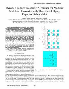
2. Circuit Configuration of MMC Fig. 1(a) is a three-phase MMC converter topology, and each phase consists of two stacks of multiple bidirectional cascaded modules and two none coupled connecting reactors. Each module works as a controllable voltage source that could generate 0 or uC voltage, where the uC is module capacitor voltage. Fig. 1(b) illustrates sub-module structure. The capacitor voltage is set as uC, and the states of S1and S1’switch complementarily with the trigger pulse. The state of the two switches determines the state of the sub-module, thus the output voltage of sub-module changes between 0 and uC. Assuming all capacitors voltages are stable in normal
†
Corresponding Author: Harbin Institute of Technology, China (
[email protected]) * Harbin Institute of Technology, China (
[email protected]) Received: December 26, 2013; Accepted: March 11, 2014
162
Shunke Sui, Rongfeng Yang and Dianguo Xu
work condition, and n-modules are active in every arm, the MMC must meet the following conditions to work properly: (1) The DC bus voltage is equal to n times of capacitors voltage at any time. (2) In the same phase, if a module in the upper arm is plug-in, a module in the lower arm is plug-out complementarily. The output voltage of each sub-module is controlled according to a certain manner. The upper and lower arms switching combinations alters, so the modules working status is constantly changing, and then the output AC voltage is n+1 level.
i pA
C
S1'
Lp
U dc
SM 1
SM 1
SM 2
SM 2
SM 2
SM n
SM n
SM n
Lp
iA
Ln
inA
Lp
iB
Ln
iC SM n +1
SM n+2
SM n+2
SMn+2
inB
U 1 1 U u x = (unx − upx ) − ( dc − dc ) 2 2 2 2 1 = (unx − upx ) 2
SM 2n
3. Modulation Strategy of MMC with Voltage Balancing Control
inC
3.1 Modulation scheme
C
When MMC is working properly, there are n working sub-modules. By changing the number of working submodule in upper and lower arm, the multilevel output is achieved. The phase shift carrier pulse width modulation (PSC-PWM) is a conventional modulation method for cascaded converters [4] which has the nature of equivalent switching frequency and duty cycle time for different modules when generating multilevel voltages.
SM 2n
(a) Power Circuit
+ U0
−
i
S1
(3)
B
Ln
SMn+1
SM 2 n
(2)
According to (1) and (2), the MMC can be characterized by the following equations:
A
n +1
SM
dipx ⎧ ⎪⎪upx = upsmx + L dt ⎨ dinx ⎪u = u nx nsmx − L ⎪⎩ dt
i pC
i pB
S1
The upper and lower arms voltage, upx and unx, can be expressed as
+ uC
VC
S 1'
ur
(b) Sub-module Fig. 1. The circuit configuration of MMC. −VC
When the system is running, according to KVL voltage law, the DC voltage, AC voltage, the sum of upper module voltage upsm and the sum of lower module voltage unsm is given by
dip x ⎧ U dc − ux − L ⎪⎪ u psm x = 2 dt ( x = A,B,C) ⎨ U di ⎪u = dc + u x + L n x ⎪⎩ nsm x 2 dt
uSM
Fig. 2. The output voltage for a sub-module. Fig. 2 shows the modulation method for a sub-module. ur is the modulation wave, uSM is the output voltage of the submodule. According to equation (3), the upper and the lower
(1)
163
An Improved Modulation Scheme for Voltage Balancing in Modular Multilevel Converter
voltage adjustments k Δ uci, and if the carrier is less than zero, the carrier minuses the adjustment k Δ uci . So it could shorten the charging time by reducing the duty ratio when the capacitor voltage is higher than average value. Similarly, when the instantaneous power is negative, it means that the capacitor is discharging and reverse operation should be employed. The proposed control scheme changes the carrier amplitude offset according to the capacitor voltage, thus dynamically adjusts the capacitor voltage to follow the average value of the leg capacitor voltage. Fig. 4 illustrates the duty ratio variation of the sub-module through adjusting the carrier amplitude offset.
arm can be looked as a two-level converter, so the two arms 0
modulation waves’ phase requires 180 difference. In the same arm, the neighbor carriers phase shifts with an angle of 2π / n . In the other arm, the corresponding carrier phase shifted by an angle of π / n .In this case, it ensures that n sub-modules are plugged in at any moment. Note that when the phase-shift angle is different, the output levels are varied [5]. 3.2 Voltage balancing control scheme On the case that the sub-module is active, if the current flows into the capacitor the capacitor is charged and the voltage increases. On the other hand, if the current flows out the capacitor, the capacitor is discharged and the voltage decreases. But when the sub-module is bypassed (the output voltage is 0), the arm current has no influence on the capacitor voltage. Therefore, the scheme that change the capacitors charging and discharging time is proposed to control capacitor voltage fluctuations. For example, when the capacitor voltage is higher than the set value, the capacitor needs to discharge, in order to reduce the voltage. Therefore, if the current flows into the Sub-module, it is needed to reduce the charging time. And if the current flow out the module, it is needed to increase the discharge time. Similarly, when the capacitor voltage is lower than the set value, it is needed to increase the charging time or reduce the discharge time, so as to increase the capacitor voltage. * ucri
Δuci
uci + −
uav
−VC
uSM t Fig. 4. The modified modulation and the output voltage of one sub-module. After adjustment of the above process, it will increase the discharge time and shorten the charging time when the module has higher capacitor voltage. However, it will increase the charging time and shorten the discharge time of capacitor when the module has lower capacitor voltage. In the process of dynamically adjusting the carrier amplitude, it could achieve a good voltage balancing control.
±1
Δucri−
k ±1
ii
VC
ucri
+
u
* cri
4. Simulation results
uci
verify the performance of the effectiveness of proposed modulation scheme, the simulation of MMC is conducted. The simulation parameters are shown in Table 1. Fig. 5(a) is shown as a capacitor voltage fluctuations without balance control, It can be obviously seen that capacitor voltage fluctuations and result in a large deviation. After long-time running, the voltage will be reduced to zero or higher enough to cause the device malfunction. Fig. 5(b) shows the proposed control strategy performance after adjustment module instantaneous power. It could be seen that the voltage maintain stable and the voltage deviation is
Fig. 3. The proposed system control block diagram. The control block diagram is shown in Fig. 3. For the sub-module i in the leg of MMC, the capacitor voltage uci subtracts the capacitor average voltage uav, to obtain a voltage deviation signal, and it is then multiplied by the factor k. When the instantaneous power of the sub-module uci ⋅ ii is positive (the current of the sub-module is ii), it means that the capacitor is charging. If the corresponding carrier is greater than zero, the carrier pluses the capacitor
164
Shunke Sui, Rongfeng Yang and Dianguo Xu
laminated under low level. It displayed that the proposed method has excellent voltage balance control effect.
quickly and efficiently. The module capacitor voltage has initial value 180V, meanwhile the setting capacitor voltage value is 200V. It can be clearly seen that the capacitor voltage has been effective regulated to normal range after several cycles. It means that this method can resist perturbations and improve the MMC system stability.
Table 1. Simulation parameters parameter DC bus voltage Number of sub-modules 2n
Value 600V 6
capacitor
2500 μ F
Inductance
4mH
Load
10 Ω 0.1 1kHz
k Carrier frequency
5. Conclusion In this paper, a novel voltage balancing modulation scheme is proposed to obtain the capacitor voltage balance. This method regulates the duty cycle time to change the capacitor charging or discharging energy through adjusting the carrier offset in PWM process, which has fast dynamic response and ability to resist perturbations. The simulation results have been presented to demonstrate the effectiveness and superiority of this method.
200 uc1/V
150 100 50 0
0
0.5
1
1.5
2 t/s
2.5
3
3.5
4
Acknowledgements
(a) Capacitor voltage without control. This work was financially supported by the Project 51237002 supported by National Natural Science Foundation of China and grants from the Power Electronics Science and Education Development Program of Delta Environmental & Educational Foundation.
200 uc1/V
150 100 50 0
0
0.5
1
1.5
2 t/s
2.5
3
3.5
References
4
[1] Hagiwara M, H. Akagi. PWM control and experiment of modular multilevel converters. Proceedings of IEEE Power Electronics Specialists Conference. Rhodes, Greece: IEEE, 2008 : 154-161. [2] Zhao Xin, Zhao Chengyong, Li Guangkai, et al. Submodule Capacitance Voltage Balancing of Modular Multilevel Converter Based on Carrier Phase Shifted SPWM Technique [J]. Proceedings of the CSEE, 2011, 21 (31) : 48-55. [3] H. Akagi. Classification, Terminology, and Application of the Modular Multilevel Cascade Converter (MMCC). Power Electronics, IEEE Transactions on, 2011, 31193130. [4] Konstantinou G S, Agelidis V G. Performance evaluation of half-bridge cascaded multilevel converters operated with multicarrier sinusoidal PWM techniques[C]. IEEE Conference on Industrial Electronics and Applications. Xi’an, China, 2009:3399-3404. [5] A .Shojiaei, G. Joos. An improved modulation scheme
(b) Capacitor voltage control. Fig. 5. Capacitor voltage fluctuations.
uc1/V
200 150 100 50 0
0
0.25
t/s
0.5
0.75
Fig. 6. The initial capacitor voltage value is 180V. Fig. 6 shows that the module capacitor voltage initial value is not equal to the normal work setting, and this method is still able to adjust the voltage to setting value
165
An Improved Modulation Scheme for Voltage Balancing in Modular Multilevel Converter
for Harmonic distortion reduction in modular multilevel converter. IEEE Power and Energy Society General Meeting. 2012 : 1-7. [6] Wang Shanshan, Zhou xiaoxin, Tang Guangfu. Modeling of modular multilevel voltage source converter [J]. Proceeding of the CSEE, 2011, 31(24) : 1-8(in Chinese). [7] Liu Zhongqi, Song Qiang, Liu Wenhua. VSC-HVDC system based on modular multilevel converters [J]. Automation of Electric Power Systems, 2010, 34(2) : 53-58(in Chinese). [8] Li Xiaoqian,Song Qiang,Liu Wenhua,et al.Capacitor voltage balancing control by using carrier phase-shift modulation of modular multilevel converters[J]. Proceedings of the CSEE,2012, 32(9) : 49-55(in Chinese).
Electrical Engineering, HIT. He was the Dean of School of Electrical Engineering and Automation, HIT from 2000 to 2010. He is now the assistant president of HIT. His research interests include renewable energy generation technology, multi-terminal HVDC system based on VSC, power Quality Mitigation, speed sensorless vector controlled motor drives, high Performance PMSM Servo System. He published over 600 technical papers. Dr. Xu is a senior member of IEEE, an Associate Editor for the IEEE Transactions on Industrial Electronics. He serves as Chairman of IEEE Harbin Section, Director of Lighting Power Supply Committee of CPSS, Vice-director of Electric Automation Committee of CAA, Electrical Control System & Equipment Committee of CES, and Power Electronics Committee of CES.
Yang Rongfeng was born in 1979. He received the B.S., M.S. and Ph.D. degrees all in engineering physics department from the Tsinghua University, Beijing, P. R. China in 2001, 2003, and 2006, respectively. In 2006, he joined the Department of Electrical Engineering, Harbin Institute of Technology as a lecturer, where he finished postdoctoral work. His research interests are focused on sensorless induction motors control and high power medium voltage application. He has published over 20 papers about these.
Sui Shunke was born in 1989.He received the B.S. degree in Electrical Engineering from the Chinese University of Mining and Technology. He is currently working toward the M.S. degree at the Harbin Institute of Technology.
Dianguo Xu received the B.S. degree in Control Engineering from Harbin Engineering University, Harbin, China, in 1982, and the M.S. and Ph.D. degrees in Electrical Engineering from Harbin Institute of Technology (HIT), Harbin, China, in 1984 and 1989 respectively. In 1984, he joined the Department of Electrical Engineering, HIT as an assistant professor. Since 1994, he has been a professor in the Department of
166