An improved optimization method for designing a doublet lens Wen-Shing SUfla, Horng Changb, Ching-Cherng Suna, Ming-Wen Chang', Chuen-Lin Tien
aJflstjte of Optical Sciences, National Central University, Chung-Li, 320, Taiwan bMaterials and Electro-Optics Research Division, Chung Shan Institute of Science and Technology, Taoyuan, 325, Taiwan cDepament of Electrical Engineering, Yuan-Ze University, Chung-Li, 320, Taiwan
dAeronautical System Research Division, Chung Shan Institute of Science and Technology, Taichung, 407, Taiwan
ABSTRACT We presented an efficient method to achieve the optimized design of a doublet lens. Using the third-order aberrations to obtain directly a minimal area from the ray-fan diagram was suggested. We took the specification of FI#=3.333 and a half field of view 1° as the design example. The optimization technique was utilized to control the third order aberrations such as spherical aberration and coma, and used the third-order spherical and coma aberrations to correct directly the on-axis aberrations. In order to minimize increasing the tendency of the off-axis aberration at the 1 .0 field angle, during the correction of the on-axis aberration a small value, then had a
tendency to increase. Our solution is taking the RMS value of spot diagram less than the diffraction limited value of point spread function (PSF) as an evaluated criterion for the on-axis aberrations. Finally, the optimized value of the system design is obtained by adjusting lens thickness and lens spacing. Two design examples of the doublet, one glass lens and one plastic lens, are well presented in this article. Keywords : Doublet, Spherical aberration, Coma, Point Spread function, Optimization technique
1. INTRODUCTION Owing to the mathematical formula of the third-order aberration is much simpler than that of higher order aberration. If we directly aimed at the third-order aberration solution, then the zero value requirement could be achieved easily, which is unique solution of the third-order aberration. However, when the third-order aberration
is approaching to zero. The real aberration, instead of decreasing, had a trend to increase. That is to say, those increasing aberrations were caused by high-order aberrations.
In this paper, with the help of a shape dependent third order aberration function, an analytical way to find the
minimum of a triplet is introduced. We find a easy to manipulate the doublet design with flexible full field controlling.
Correspondence : Email:
[email protected]; Telephone: 886-3-4276240; Fax: 886-3-4252897
146
Novel Optical Systems Design and Optimization IV, Jose M. Sasian, Paul K. Manhart, Editors, Proceedings of SPIE Vol. 4442 (2001) © 2001 SPIE · 0277-786X/01/$15.00
Downloaded From: http://proceedings.spiedigitallibrary.org/ on 04/22/2015 Terms of Use: http://spiedl.org/terms
2. THEORY 2.1 RMS spot size The spot diagram is related to the geometrical spot size of the image and the radial energy distribution. With the definition of the radial transverse aberration as 2
2
2
(1)
TATAX+TAY
These ray transverse aberrations TA and TALl, are measured with respect to the image, for the d line. The average
transverse aberration is the height of the centroid of the image. Taking into account the symmetry about the merridional plane, it may be written as
TA'TA N —
(2)
where N is total number of rays, and the sum is performed overall the rays in the spot diagram. The geometrical
spot size is easily defined in terms of the transverse aberrations, by the variance of the transverse aberrations, which is the square of the room mean square spot size TArms as follows
TA+(TA_TA)2= TA2 —TA2 '=
TA2 rms
1=
N
(3)
N
as described above, the diffraction limit = 1 .22f/# = 1 .22xO.5876umx3.3333 2.389x 10 3rnm.
2.2 The design philosophy The merit function"2 is strongly related to the spherical aberration S1 and coma S11
2
2
2
2
ç = W1 (s1 _t1 ) + w2(s11 _t11 ) (4) The w's
and
'
are the weighting factors and target values as usual. There are only two aberrations, so it is
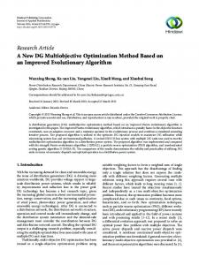
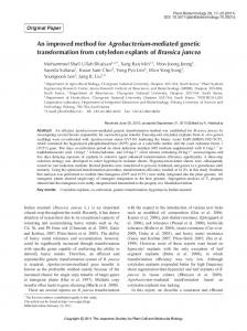
easy to calculate the two shape factors of the target values t1 t11 by the merit function program. The shape factor obtained from the optimized process will make the lens power change correspondingly. The design optimized process is shown in the flow chart in Fig. 1. If we start with our procedure, i.e. place all of the target values as zero, we can obtain a lens design with the two shape factors, spherical and coma aberrations,
being approximate zero. First of all, we use
and tsH to optimize an on-axis aberration, until the on-axis
RMS spot size is less than diffraction limit. Finally, we adjust the lens thickness and lens spacing to reduce both
on-axis aberration and off-axis aberration 1.0 field simultaneously, thus an optimization value design was obtained.
Proc. SPIE Vol. 4442
Downloaded From: http://proceedings.spiedigitallibrary.org/ on 04/22/2015 Terms of Use: http://spiedl.org/terms
147
3. DESIGN EXAMPLES We define weighting factor of wavelength as follows:
0.4861 m weighting factor =1 0.5876 m weighting factor =2 0.6563 m weighting factor =1
wavelength
BU1 is defined as the area of meridional ray emerging from the entrance pupil which is relative to aberration,
BU2 is the area of sagittal ray emerging from the entrance pupil which is relative to aberration, and BU=BU1+BU2.
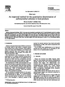
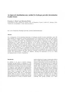
3.1 The design of minimal on-axis aberration If we only optimized a design for the on-axis aberration, and regardless of other field angle aberration, then the
result was obtained and shown in Fig. 2. The ray-fan plot shows an on-axis aberration BU1 3.904359xl0 , which at half field angle of 0.7° indicated BU = 5.O85934x 1 0 _3; and at half field angle of 1 .00, BU
and
7.29O392xlO
On-axis RMS spot size is 6.42OO82çj 4mm, and polychromic RMS wavefront of on-axis
aberration is 0.0255 , the aberration at 0.7 field is 0.0575 ,
and
that of 1.0 field is 0.0806 . The on-axis
aberration has reached the minimum, but the variation of off-axis aberration is very large at half field angle of 1.00.
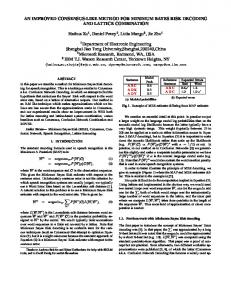
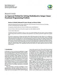
3.2 The optimization design over the full field Figure 2 shows that an off-axis aberration is increasing during optimized the on-axis aberration. For good quality, we must consider both on-axis aberration and off-axis aberration over half field of 1 .0°. Hence we present an improved method on the on-axis aberration optimization, using RMS spot size less than diffraction limit as a criterion to cut-off the optimization over on-axis aberration and off-axis aberration over half field of 1.00. Figure 1 shows the flow chart of the optimization, firstly optimized the on-axis aberration to achieve RMS spot size < diffraction limit, then evaluated the off-axis aberration (BU) over half field of 1.0° whether the value
is going down. If yes, then we keep going to optimize the on-axis aberration up to the minimum of an off-axis aberration over the half field of 1 .0° and then cut-off the optimization. If not, we choice the on-axis aberration
to fulfill the criterion, RMS spot size = diffraction limit, and stop the optimization program. If we adjust again the lens thickness and lens spacing to find an optimum design of the system in full field, as shown in Fig. 3. For
the ray-fan plot, the on-axis aberration BU1 = 9.685787x10 4.0691 63x 10
; the aberrations at 1.0 field is BU =
5.5501 95x
,
the
aberrations at 0.7 field is BU =
10 , respectively. On-axis RMS
spot size is
2.2l5346x10 3mm, and polychromic RMS wavefront of on-axis aberration is 0.0250k, the aberration at 0.7 field is 0.0435k, and that of 1.0 field is 0.0605k.
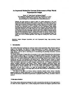
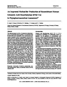
4. PLASTIC DOUBLET DESIGN We choose the plastic lenses PMMA (nd = 1.49 18, vd = 57.4) and PS(nd = 1.5905, vd = 30.9) to design a doublet
148
Proc. SPIE Vol. 4442
Downloaded From: http://proceedings.spiedigitallibrary.org/ on 04/22/2015 Terms of Use: http://spiedl.org/terms
lens. Fig. 4 shows the optimization design. In ray-fan plot, the on-axis aberration BU1 is = 4.647494x10
', the
.
aberrations at 0.7 field are BU = i.247iix10 _3; the aberrations at 1.0 field are BU = 2.O77495xl0 On-axis RMS spot size is i.091974xl0 and polychromic RMS wavefront of on-axis aberration is O.O419, the aberration at 0.7 field is O.0366X, and that of 1.0 field is O.O367. The design result compared with Fig. 3, only on-axis aberration is large but the off-axis aberration is small
5. CONCLUSION We have presented an improved optimization method for doublet lens design. For the application of collimator lens design, the minimum value design of an on-axis aberration can be obtained. If considering the optimization
of the off-axis aberration, then must sacrifice an on-axis aberration to get the optimized value design over the full field-of- view. The use of doublet plastic lens is promising in the near future..
REFERENCES 1. D. P. Feder, "Automatic Optical Design," Appl. Opt. 2,pp.l2O9-l226 ,1963. 2. T. H. Jamieson, Optimization Techniques in Lens Design (1971).
Proc. SPIE Vol. 4442
Downloaded From: http://proceedings.spiedigitallibrary.org/ on 04/22/2015 Terms of Use: http://spiedl.org/terms
149
start solve initial value
tS1O, t11=O fix
change
t1
t c corrects axis ray-fan aberration
fix tS1' change tS11 t corrects axis ray-fan aberration
Fig. 1 The optimized program flow chart for doublet design
150
Proc. SPIE Vol. 4442
Downloaded From: http://proceedings.spiedigitallibrary.org/ on 04/22/2015 Terms of Use: http://spiedl.org/terms
NO SURFACE
1
stop
2
sphere
3
sphere
4
sphere
S sphere
MEDIUM
air air
LENGTH
CURVATURE
HATER IAL
INFINITE
8
S1= 7.988683E—84 52= 6.45999E—84 C1= 3. 648527E—84
8
.2332228
glass
.75
K3
C2=—1 - 347691E—85
— - 2766482
air
.8162
— .2762776
glass
.25 —-
P4
8867136
hFOV= 1 BFL= 9.212838 EFL= 18 Meridian ( 8 —Degree ) L29 x103
1/11= 3.333
( 8 —DEGREE)
0
0)
r
Vt ______
::-i
8
1
C .\58
—1 .29x103 BU1 = 3. 984359E—84 Ray height
2.573555E—83
spot
RHS
Meridian ( .7 —Degree ) 6.34 x10³
size
Sagittal
C
= 6.428882E—84
.7 —Degree )
1 .58x103
0
0
Ia
It c-I
Vt
1 58
c-8
c-—1.58
a.'
a.'
C
C
—6 .34x103
—1.58 Ray height BU2= 2. 548875E—84
BU1=4.831127E—83 Ray height BU= 5.885934E—83
Meridian C 1
—Degree
8 .81x103
)
Sagittal
C 1 —Degree )
1.72 xltT3
S
S
0 It
0 Ia
8
c-8 a.'
j1S8 —8 81x103
C —1 .72x103 Ray height BU2= 3. 826578E—84
BU1= 6. 987735E—83 Ray height BU= 7.298392E—83 (a)
Proc. SPIE Vol. 4442
Downloaded From: http://proceedings.spiedigitallibrary.org/ on 04/22/2015 Terms of Use: http://spiedl.org/terms
151
0. 1 000 H
0.0900
I
0.0800
z H
I I z0 II 0 I
0,0700 0.0600 0.0800
H
0.0100 0.0300
W
0.0200
H
0.0100 0 0000 0 .
8000
+Y FIELD IN DEDREES
RMS HALEFRONT ERROR US FIELD LENS HAS NO TITLE. SAT MAY 26 2001
HOLY 0.H86 0.588 0.656
REFERENCE
A: \OOU8LET\TESTA. ZMX
CENTROID
1.0 .9
I H
0
.8
.7
I , W
H
0 0 -J o 00 o
.5 H
.
.0 3 16 .
36
SPATIAL FREQUENCY IN CYCLES PER MILLIMETER POLYCHROMATIC DIFFRACTION MODULATION TRANSFER FUNCTION
HAS NO TITLE. SAT MAY 26 2001 DATA FOR 0.8b1 TO 0.6563 MICRONS. LENS
,
E: \DOU8LET\TESTA . ZMX (c)
Fig. 2 The design of minimal on-axis aberration
152
Proc. SPIE Vol. 4442
Downloaded From: http://proceedings.spiedigitallibrary.org/ on 04/22/2015 Terms of Use: http://spiedl.org/terms
NO SURFACE
1
stop
2 sphere 3 sphere 4 sphere
5 sphere
MEDIUM
CURVATURE
air
LENGTH
MATERIAL
INFINITE H
air
S1= 1.273492E—H4 S2= 4.706526E—H4 C1= 4.H54H65E—H4
H
.22H2552
glass
1.H5
K3
— .2954956
air
C2=—1 .834392E—H5
.H15 — .2949546
.23
glass —
F4
. H199952
F/#= 3.333 hFOV= 1
BFL= 9.H45922 EFL=
1H.HHHH1
Meridian ( H —Degree )
( H —DEGREE)
4 .5?x103
0
1. I
—4 .57x103 13U1= 9. 665787E—H4 Ray height
RMS spot
Meridian C .7 —Degree ) 0 .H6x103
1-1IH —o .06x103 BU1= 3.589833E—03 Ray BU= 4.H69163E—H3
1H
height
Meridian C 1 —Degree ) 9 .05x103
k
9.12H682E—H3
size =
I
2.215346E—H3
Sagittal C .7 —Degree ) 4.70x10³
—4
.?8x1O3
T
Ray height BU2= 4. 7933H0E—H4
Sagittal C 1 —Degree ) 5 .HHxIO3
0
—9 .85x103 BU1= 5. 016018E—03 Ray height
—5 .HHxIO3 Ray height BU2= 5. 3417?E—H4
BU= 5.550195E-03
Proc. SPIE Vol. 4442
Downloaded From: http://proceedings.spiedigitallibrary.org/ on 04/22/2015 Terms of Use: http://spiedl.org/terms
153
0. 1000
3 3
I z I0I I H
w
0 .
0900
0 .
0800
0 .
0700
0 .
0600
0 .
0900
H
z0
0. 0H00
UU-
0 .
0300
0 .
0200
0 .
01
0 .
0000
I 0 I3 I C')
00
+Y FIELO IN DECREES
RMS NADEFRONT ERROR US FIELD LENS HAS NO TITLE.
FRI MAY h11 POLY 0
0.588 0656 E;\DOU8LET\TEST2,ZMX
REFERENCE
CENTROID
1.0 .9 .8 U-
H
0
.7
W
I
.6
H
3 0 0 0 0
.b L
.3 ,
.0
POLYCHROMATIC DIFFRACTION MODULATION TRANSFER FUNCTION LENS HAS NO TITLE. FRI MAY 11 2001 DATA FOR 0.H8E1 TO 08963 MICRONS E: \O OU8LET\TEST2
(c) Fig. 3 The optimization design over the full field
154
Proc. SPIE Vol. 4442
Downloaded From: http://proceedings.spiedigitallibrary.org/ on 04/22/2015 Terms of Use: http://spiedl.org/terms
ZMX
NO SURFACE MED JUM
1
stop
2
sphere sphere
3
sphere
4
S sphere
air air
LENGTH
CURVATURE
HATFP TAT.
INFINITE B
S1= .000325
B . 1665244
plastic
air plastic
.61
S2=— .00001
C1= 1.306649E—04
PMMA
— .2729356
C2=—1 .266017E—05
.06 — .2610529
.32
PS
— .065363
F'#= 3.3J3 hFOV= 1
BFL= 9.1EnJ?43 EFL= 9.999999 C B —DEGREE) Meridian C B —Degree )
2 .25x103
0
t-ir
B
C
.25x103 Ray height
'V
I
—2
BIJ1=4 . 647494E—04
RMS spot
4.497729E—03
size =
Sagittal
Meridian C .7 —Degree )
C
I
1.091974E—03
.7 —Degree )
2 .47x103
4 .07x103
0
.—
41.5B
to
B
C
C —4
.B7x103
—2 .47x103 Ray height BU2= 2. 6B1326E—B4
BU1= 9. 669769E—B4 Ray height BU= 1.24711E—B3
Sagittal C 1 —Degree ) 2 .69x103
Meridian C 1 —Degree )
5. 16x103
0
ti.s
40
B
C
C
—2 .69x103
—5. 16x103
Ray height BU2= 4. 25633E—B4
BU1= 1. 651662E—B3 Ray height BU= 2. B7?495E—B3 (a)
Proc. SPIE Vol. 4442
Downloaded From: http://proceedings.spiedigitallibrary.org/ on 04/22/2015 Terms of Use: http://spiedl.org/terms
155
8. 1000 U)
0.0900 0.0800
z H
3
0.0600
3 w H
z0
0.OHOO
3 3
3 0
0.0300
I
0.0200
U)
0.0100 0
0000
0 5000 +Y FIELD IN DECREES
RMS 8ADEFRDNT ERROR US FIELD LENS HAS ND TITLE.
FRI MAY
1
PDLY
REFERENCE
1
0 888 0 656 E \DOU8LET\TEST8X ZMX
CENTRDID
1.0 .9
.8 U-
c .7 H
I
w H U-
0 U)
.6 .8 H
0 0 0 3
.3
.0
311 93
SPATIAL FREOUENCY IN CYCLES PER MILLIMETER PDLYCHRDMATIC DIFFRACTION MODULATION TRANSFER FUNCTION LENS HAS ND TITLE. FRI MAY 11 2001 DATA FOR 0,H861 TO 0.6863 MICRONS. E \DDU8LET\TEST8X . ZMX
(c) Fig. 4 The plastic doublet design
156
Proc. SPIE Vol. 4442
Downloaded From: http://proceedings.spiedigitallibrary.org/ on 04/22/2015 Terms of Use: http://spiedl.org/terms