Abstractâ This paper focuses on the amount of processed data in communication network, transmitting power control and the number of terminals that should ...
ISSN 2249-6343 International Journal of Computer Technology and Electronics Engineering (IJCTEE) Volume 4, Issue 2, April 2014 (An ISO 9001: 2008 Certified International Journal)
An Improved Method of Using Throughput in Optimization of Data Transmission Network. Udeh I.J,1, Ugwu O.C2 ,Eneh I.I2 Department of Electrical Electronic Engineering Enugu State University of Science and Technology, Nigeria.
CDMA is a form of spread spectrum, a family of digital communication techniques that have used in so many application for years. A basic property of spread spectrum is a substantial increase in bandwidth of an information bearing signal far beyond that needed for basic communication and spread spectrum systems generally fall into one or two categories frequency hopping (FH) or Direct Sequence. Both forms can be regarded as using a pseudorandom carriers but they create the carrier of the signals in different ways and synchronization of transmitter and receiver is required.
Abstract— This paper focuses on the amount of processed data in communication network, transmitting power control and the number of terminals that should be admitted in to code division multiple access (CDMA) system in order to maximize the base station throughput for a wireless data transmission network. Also a simulator was developed for effective handling of issues for number of terminals. It was discovered that when noise and interference are negligible, received power balancing maximizes the base station throughout, provided the population of active terminals does not exceeds an optimum size. However, throughput is the average rate of successful message delivery over a communication channel. This data may be delivered over a physical or pass through a certain network node. Keywords: CDMA, Modulation scheme, Propagation characteristics
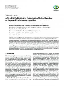
Code and modulat e
I. INTRODUCTION Users of telecommunication devices, system designers and researchers involved in communication theory are often interested in knowing the expected performance of a system following the success of cellular telephone services in the 1990s, the technical communities has turned its attention to data transmission such as code division multiple access which has become the focus of current research to provide higher data rates for end users over a wireless channels. The throughput of a wireless data communication system depends on a number of variables which includes, packet size, transmission rate, the number of overhead bits in each packet, received signal power, received noise power spectral density, modulation technique and channel conditions. The major key to maximizing throughput is maintaining the (SINR) at optimum level. Signal Noise Ratio (SINR)..
v
Pseudo- Noise Carrier
Fig. 1 Direct Sequences II. MATH Code Division Multiple access transmitter block of a more conventional communication wave form by a pseudo noise (PN) 1 burery sequence in the transmitter.
Code Division Multiple Access (CDMA) is a third generation (3G) Technology that provides users (mobile stations) both within and across a different cells to transmit and receive on the entire frequency spectrum.
1
ISSN 2249-6343 International Journal of Computer Technology and Electronics Engineering (IJCTEE) Volume 4, Issue 2, July 2014 (An ISO 9001: 2008 Certified International Journal)
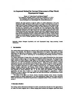
Demodulator and Decode
III. Pseudo-Noise Carrier Fig. 2 Direct Sequence of Code Division Multiple access Receiver Block Diagram
A second multiplication by a replica of the same sequence in the receiver recovers the original signal. There are two CDMA common air interference standards.
IV. METHODOLOGY A data source generates packets of height L bits at each terminal of CDMA system. A forward error correction (FEC) encoder is presents and cyclic redundancy check (CRC) encoder together expand the packet size of megabits. The data date of the coded packets is RS b/s. The throughput optimization in this paper in CDMA networks spread the signals to product Rc chips/S. The CDMA processing gain is G = W/Rs - - - - - - (1) Where W(HZ) is the system bandwidth and is proportional to RC. The gain from transmitter 1 to the base station is hi and the signal from terminal 1 arrives at the base station at the received power level of Q1 = Pi hi (W) - - - - - (2) In mathematical function f(x) which is the probability that a packet arrives at cyclic redundancy check decoder without errors. The dependent variable y is the received SINR for terminal i. Y = G Pi hi N N pihi + 2 - - - - - - (3)
Forward CDMA Channel: This is the call to mobile direction of communication. It carriers traffic, a pilot signal and overhead information, the pilot and overhead channels establish the system timing station identity. Reverse CDMA: This is the mobile to cell direction of communication. It carriers traffic and signaling. Digital Modulation Scheme: The choice of digital modulation scheme will significantly affect the characteristics, performance and resulting physical realization of communication system. Consideration must be given to the required bandwidth, required data rate, acceptable level of latency, anticipated link budget, size and current consumption. II. PROPAGATION CHARACTERISTICS Microwave point links are typically designed with slim margins as the channel will vary with time, with the exception of possible increased loss from gain, however, mobile communication system operating at vary high frequency (VHF) and ultra high frequency (UHF) band are typically not lime of sight and therefore consists of the sum of signals from different path. Potentially this will result in intersymbol interference due to delay spreads as well as considerable amplitude variations with time or distance. Physical object will cause showdowing resulting in loss of signal and additionally due to varying proximity between two nodes.
J=1 =1
Substituting (2) into (3) Yi = G Q1 N Qi + 2 - - - - - (4) J=1 =1
2
ISSN 2249-6343 International Journal of Computer Technology and Electronics Engineering (IJCTEE) Volume 4, Issue 2, April 2014 (An ISO 9001: 2008 Certified International Journal) axis (L0 6 0 25); When 2 > 0, the signal to noise ratio of the receiver is defined as Si = Q1/2 - - - - - - - (5) Substituting (4) we have Y1 = G Si N Si + 1 - - - - - (6) J=1
If the probability of undefected errors at the CRC decoder is negligible, the throughput of signal i defined as the number of information bit per second received without error is T1 = L RSF (Y) b/s M Where T is the throughput of terminal i (b/s) L is the packet length (bit) M is the packet size RS is the packet data rate (b/s) F (Y) is the probability function Assuming that L M and RS are system constant, the aggregate throughput, Ttotal - - - - - - (7) The normalized throughput is analyzed as; U = M Ttotal = N F(Y)i - - - - - (8)
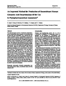
Fig. 3. We observed that a small value of propagation exponent for terminal yields a wide operational range (longer distance) and thus a significant increase in the system performance that a lager value of the propagation exponent. However increase value of the propagation exponent for terminals leads to more frequent attenuation of signal, thus yielding reduced operation range and higher signal noise rated terminal.
J=1
u Q1 = Q1 0; 2 = 0 - - - - - (9) Q1 u Q1 = Q >0, 2 = 0 - - - - - (10) Q1
IV. DATA PRESENTATION, ANALYSIS AND RESULT V. CONCLUSION The simulator has a graphical user interface (FU1) that captures data corresponding to the parameters in the model. Empirical input were made and result were obtained from the simulation. In analysis the effect of distance (d) – on the propagation exponent was simulated against distance (d).
We have been to optimize the throughput in CDMA networks through power control by simulating models with relevant parameters. Some practical issues regarding the application of this paper throughput optimization for wireless data transistor network in CDMA have bee identified and series of investigations identifying the key features and parameters as well as how they influence CDMA systems network have been presented. Numerical results and discussion have shown that the interference generated by users of the network in the form of noise has been minimized with the help of the model derived which can aid in transmitting signals to the base stations of CDMA system with equal strongest power. Finally the future of the second generation (2G) network technologies such as GSM is highly uncertain due to rapid development and widespread of the third generation technologies.`
MATLAB CODE FOR DISTANCE VS PROPAGATION EXPONENT X = 0:1:6 T = 0:5:25 T = (29.387) *exp (-0.586.*(x)); Plot (X, Y,) Grid on% insert grid lines Xlabel (‘propagation exponent’)% x – axis label. T label (‘Actual Distance )d))% T axis label
3
ISSN 2249-6343 International Journal of Computer Technology and Electronics Engineering (IJCTEE) Volume 4, Issue 2, July 2014 (An ISO 9001: 2008 Certified International Journal) REFERENCES [1]
Andrew J. Viterbi, (1995) “Principles of Spread Spectrum Communication”, Addison- Wesley, Wireless Communications Series.
[2]
David J. Goodman, (1997) “Wireless Personal Communications Systems.” Addison-Wesley, Wireless Communications Series.
[3]
David J. Goodman, Narayan Mandayam, (2000) “Power Control for Wireless Data,” IEEE Personal Communications.
[4]
J. Zander, (1992) “Distributed Co-Channel Interference Control for Cellular Radio Systems,” IEEE Trans. Vehic. Tech. Vol. 41.
[5]
Jeongrok, Yang, Insoo, Koo, Yeoongyoon Choi, and Kiseon Kim, (1999) “A Dynamic Research Allocation Scheme to Maximize Throughput in Multimedia CDMA System/ Vehicular Technology Conference.
[6]
John G. Proakis, (1995) “Digital Communications.” McGraw-Hill, Inc., Third Edition.
[7]
Seong-Lyun Kim, Zvi Rosberg and Jens Zander, (1998) “Combined Power Control and Transmission Rate Selection in Cellular Networks,” IEEE Personal Communications.
[8]
Shah (1998) “Power Control for Wireless Data Services based on liability and pricing, , “MS Thesis, Rutgers University.
4