thin, sliced and horizontally placed. Additive manufacturing technology saves time and cost for developing 3D models by eliminating separate designing, ...
An in-depth Study of Implementation Issues of 3D Printer Debasish Das 1, Indrajit Pandey2, and Jyoti Sekhar Banerjee1 Department of Electronics & Communication Engineering, Bengal Institute of Technology Kolkata, West Bengal, India Department of Electronics & Instrumentation Engineering, Techno India College of Technology Kolkata, West Bengal, India 1
2
design and implementation steps of any 3D printing process. The rest of the paper is described as follows. Section II presents working principle of 3D printer. In Section III, we discuss the integral parts of 3D printer. Section IV provides the application areas of 3D printer. Finally, in Section V and VI, we provide future scope of 3D printer and discuss some concluding remarks.
ABSTRACT The making of three dimensional object from a digital file involves a process called Additive manufacturing. Using Additive process, an object is developed by laying down of consecutive layers of materials till the object is manufactured entirely. If we consider the cross section of the object then it is clear to us that every layer is prominent as a thin, sliced and horizontally placed. Additive manufacturing technology saves time and cost for developing 3D models by eliminating separate designing, printing and glue together individual printed parts. Henceforth we may develop a complete model in one single process using 3D printing which finally leads to increasing flexibility. Keywords: 3D Printing, Slicing Software, CAD Image, Filament, Extruder Assembly, Print Bed.
I.
INTRODUCTION
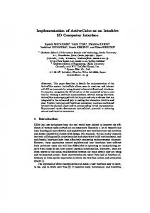
Fig. 1. 3D Printing Process Layer by Layer.
Late 1980’s witnessed the first 3D printing technologies. A rapid prototyping [1] [11] [12] technology was the name given to those printers that went through further development to give birth to 3D printer. The more cost effective method for creating prototypes and the processes being originally conceived as fast lead to such nomenclature. Dr. Kodama filed the very first patent application for Rapid prototyping technology in Japan in May 1980.The process of making 3D object using additive process (see fig.1) [5][6] from a digital file is called 3D printing. The method has proved to be cost effective and time saving. The model in its entirety can be created through single process. Flexibility is increased by using this technology in Jewelry, footwear, industrial design, architecture, engineering, construction, automotive, dental and medical education, and several other fields those are directly or indirectly is benefitted by the application of the 3D printing. We can manufacture [4] [7] the duplicate copy of any Physical object using 3D printer which is scanned with a scanner or designed in CAD tool. In this paper, we focus on the implementation issues of 3D printing technology. The major contributions of this paper are defined as follows. Firstly, we explain the in-depth
Fig. 2. CAD Image.
II.
WORKING PRINCIPLE OF 3D PRINTER
First we have to create the virtual 3D design. This virtual design can be made using CAD (computer aided design) (see fig. 2) [9] [10] or with 3D scanner to copy an existing object. A 3D scanner makes a copy of the existing object into CAD format. 3D scanner uses different technologies such as time
32
of flight, structured/modulated light, and volumetric scanning. Many companies like Microsoft, Google has introduced a hardware to perform 3D scanning, such an example is Microsoft’s Kinect. This is a sign that future hand-held devices like smart phones will be integrated 3D scanners to scan objects of any kind. Price of 3D scanners ranges from very expensive industrial devices to DIY (do it yourself) devices that anyone can make at home. There are different types of 3D printers. Fused deposition modeling (FDM) is a method of Rapid Prototyping is the most commonly used additive technology. It includes 1. nozzle ejecting molten material (plastic), 2. deposited material (modelled part), 3. controlled movable tab. Plastic filament or metallic plastic filaments are used in FDM technology. Filament is unwounded from a coil and then it is passed on to the heated extrusion nozzle. The flow of material passing through the nozzle can be adjusted using the controller of the 3D printer connected to a computer. The material is melted while passing through the heated nozzle which can be moved in both vertical and horizontal direction by a numerical controlled mechanism directly controlled by a computer aided manufacturing (CAM) software. Layers are formed by extruded melted material in layers to produce an object. After extrusion from the nozzle, the material hardens immediately. ABS and PLA are two common plastic filament used widely with this technology. III.
Fig. 3. Slicing Software.
Fig. 4. 3D printed complex objects after calibration.
B. Filament PLA and ABS are the most frequently used plastic raw material as fused filament for 3D printing. PLA filament is a biodegradable corn based polymer [15] [16] filament which needs to be preheated to about 1850C (3650F) before its extruding and bonding well. (Temperatures in 3D printing are given in Celsius.) ABS (acrylonitrile butadiene styrene) is a thermoplastic that requires a higher temperature (~2400C, or 4640F) for use in 3D printing. It tends to be smooth and strong. While melted PLA may smell slightly sweet, melted ABS can give off a burnt plastic odor, and has been known to cause headaches, so it's best used in a wellventilated area. Recently, filament Maker (see fig. 5) can be used to make filament which will reduce the cost of buying readymade filament from the shop which costs 2000 in Indian rupee per spool of 1kg weight.
INTEGRAL PARTS OF 3D PRINTER
A. Software 3D printers are generally computer mediated and require a number of programs like Slic3r and a print control program like pronterface. The programs are often bundled by 3D printer makers to optimize the package for their models.3D models is taken in STL format by the slicer software (see fig. 3 & 4) which then” slices” the designed object into layers for printing based on layer height or resolution of the desired object and some other parameters that is previously set from within the slicer. STL (stereolithography) is a file format innate to the stereolithography cad software. Many software packages support this format. It is mainly used for Rapid prototyping, 3D printing and computer-aided manufacturing. The object is saved in G-code format when sliced. The extruder gets heated up and the temperature gets controlled by the print control software which also moves the extruder in 3 dimensions. The minimum possible distance between the build platform and the extruder is set with the help of it.
Fig. 5. Filament maker Frame.
33
Fig. 7. Dual head extruder with inductive sensor for z-axis and extruder head cooling fan.
Fig. 6. Advance dual head extruder 3D Printer.
3D printers (see fig. 6) have an open frame. Open frames let you to clearly see the job in progress, but have two drawbacks. One is noise due to having four motors; several of them frequently switching directions, 3D printers can be noisy. A closed frame can eliminate much of the printing noise. Printing with ABS material produces harmful fumes which can be a big issue with an open frame that offers no protection from these harmful fumes. If you do print with ABS on an open-frame printer, be sure to have a fan nearby, and keep your windows open, if possible. Recently due to vibration problem, the frame is being made of acrylic plastic of thickness 6mm minimum so as to absorb the noise produced during printing. This update will also decrease vibration as well as the weight of the overall printer. So the portability problem of the 3D printer will be solved
After few researches on extruder a modified form is being introduced in 3D printer category. The single and dual extruder can be replaced with multicolor extruder having single nozzle to extrude the filaments. This update will
C. Extruder Assembly (aka print head)
D. Print Bed
1. 2. 3. 4. 5.
The convectional printer’s print head is an analogue to the 3D printer and is known as extruder (see fig. 7). At the extruder’s bottom is a nozzle which is found adhered to it. The working of the 3D printer first includes a liquefied plastic being squirted out from the nozzle above which is a melting chamber in which the plastic [17] filament is melted by a heating element before extrusion. The filament is feed into hole situated at the top of the assembly. A motor gear is found fitted with the filament strand. The motor gear when turned, feeds it into the melting chamber.
Decrease the size of the extruder. Decrease the load on the x-axis thus stepper motor can now perform with great speed without any issue. Increase portability Reduce the price as one extruder is extruding different kinds of filaments. Only one stepper motor is being used for extruding multiple filaments unlike dual extruder which uses two stepper motor to extrude two different color only
Fig. 8. Heat Bed [18].
The print bed (see fig. 8) or build platform is the surface on which the object is printed. It will be at least as large as the
34
width and depth of the printer's build area (the size of the largest object it's capable of printing). It is often treated to allow the object to adhere to it while printing. You need to apply glue before each printing to the Printer's build platform, and then rinse it under running water to soften the glue when the job is finished.
printing, the printer will remain idle. It is very much challenging to remove the printed object from the heat bed. We can use few drops of water for soften the glue that hold the printed object to the heat bed & with care the object is removed from the heat bed. Now 3D printer is more portable by using wireless communication technology to print 3D objects without any requirement of connecting computers to the 3D printer using wires. So, to print an object, the. stl file will be simply transferred to the printer motherboard containing SD card to store the data and then to execute the process of 3D printing.
The readymade 3D printer bed is not efficient in terms of money as well as the power consumed by the bed. This readymade bed took lot of time to get heated up to reach 100 degrees in isolated place, so printing abs on this heat bed is difficult as heat bed should reach minimum of 100 degrees centigrade to stick abs material on the bed. It can be replaced with aluminum or copper (costly but best conductor heat) with heat resistor of 10k ohm to heat the heat bed (see fig. 9). Again the numbers of resistor to be attached to the aluminum or copper clad depend on the size and the thickness of the clad.
IV.
APPLICATION AREAS OF 3D PRINTER
3D printer is user friendly and it takes very less time to print any kind of object with accurate resolution. The following application some [2] [3] [8] [12] areas of 3D printer are:
Bio -printing 3D printing has been studied by biotech firms for possible use in tissue engineering application where organs and body parts are built using inject technique [14].
Automotive industry The use of 3D printing in automotive is to manufacture models for design verification, vehicles, engines, and platforms.
Fig. 9. Modified heat bed.
E. Motion
Aerospace & aviation industries The growth in utilisation of 3D printing in the aerospace and aviation industries is huge.3D printing technology is used in Aerospace & aviation industries to manufacture engines ,model and for design verication
The extruder assembly and print bed move relative to each other in three dimensions—X (side to side); Y (in and out); and Z (up and down)—in order for the extruder to sequentially deposit the layers of molten plastic to create the object. This is done by means of motors—one for each axis—connected to belts. V.
F. Printing Depending on the type of plastic used in the melting chamber starts heating up to the desired temperature on the initialization of the print command. The extruder, almost touching the build platform moves to its starting point. Printing process will start when the extruder is hot enough to melt the plastic filament. According to the instruction, the extruder will move relative to the build platform to deposit plastic layer after layer. The first layer is generally pressed against the print bed due to the extruder’s proximity to the build platform. One thing we need to remember that layer height of the 3D printer is its resolution and it is measured in microns, or a millimeter. Typical resolutions range is between 100 and 250 microns or 0.0039 to 0.0088 inches. The extruder will generally move away from the printed object on the completion of the printing and until next
FUTURE SCOPE IMPLEMENTATION
OF
3D
PRINTER
3D printer is costly due to the material used to make it and all the electronic parts in it. But it can widely be available to everyone by using electronic waste device (see fig.10) [11] [13] such as scanner, CD drives to make 3D printer which will costs less to nothing.
35
Industry, Vol. 41, pp. 3-24. [5] Brown, S. and Bessant, J. (2003), “The manufacturing strategycapabilities links in mass customisation and agile manufacturing – and exploratory study”, International Journal of Operations & Production Management, Vol. 23 No. 7, pp. 707-30. [6] Buswell, R.A., Soar, R.C., Gibb, A.G.F. and Thorpe, A. (2007), “Freeform construction: mega-scale rapid manufacturing for construction”, Automation in Construction, Vol. 16, pp. 224-31. [7] Buswell, R.A., Thorpe, A., Soar, R.C. and Gibb, A.G.F. (2008), “Design, data and process issues for mega-scale rapid manufacturing machines used for construction”, Automation in Construction, Vol. 17, pp.923-9.
Fig. 10. 3D Printer using waste electronic device.
VI.
[8] Campbell, R.I. and de Beer, D.F. (2005), “Rapid prototyping in South Africa: past, present and future”,Rapid Prototyping Journal, Vol. 11 No. 4, pp. 260-5.
CONCLUSION
[9] Chang, J.W., Luh, Y.P. and Chiou, S.S. (1997), “Integrated application in CAD/CAM, scheduling and control”, Integrated Manufacturing Systems, Vol. 8 No. 6, pp. 378-87.
3D printing is an expanding technology as any virtual designed object can be printed into physical object with ease. Such technology has a blooming prospect and will soon start an industry in which everyone will have a possibility of being a manufacturer. This method is cost effective and time saving.3D printer has lots of possible benefits that will help in the progress of society.
[10] Chen, C.-S. and Wu, J. (1994), “CAD/CAM systems integration: an integrated surface and volume feature modelling scheme”, Integrated Manufacturing Systems, Vol. 5 Nos 4/5, pp. 22-9. [11] Dimitrov, D., Schreve, K. and de Beer, N. (2006), “Advances in three dimensional printing – state of the art and future perspectives”, Rapid Prototyping Journal, Vol. 12 No. 3, pp. 136-47.
VII. ACKNOWLEDGEMENT The authors deeply acknowledge the support from the department of ECE, Bengal Institute of Technology (A unit of Techno India Group) & the department of EIE, Techno India College of Technology (A unit of Techno India Group). The authors also wish to express appreciation to Prof. Debanshu Ray, Director, Bengal Institute of Technology, Prof. (Dr.) Bibek Chakraborty, Principal, Bengal Institute of Technology & Prof. (Dr.) Sanjib Sil, Techno India College of Technology for their continuous support and inspiration. VIII.
[12] Dimitrov, D., Schreve, K., Taylor, A. and Vincent, B. (2007), “Rapid prototyping driven design and realisation of large components”, Rapid Prototyping Journal, Vol. 13 No. 2, pp. 85-91.
[13] Leigh SJ, Bradley RJ, Purssell CP, Billson DR, Hutchins DA (2012) A Simple, Low-Cost Conductive Composite Material for 3D Printing of Electronic Sensors. PLoS ONE 7(11): e49365. doi: 10.1371/journal.pone.0049365 [14] Murr LE, Gaytan SM, Medina F, Lopez H, Martinez E, et al. (2010) Next-generation biomedical implants using additive manufacturing of complex, cellular and functional mesh arrays. Phil Trans R Soc A 368: 1999–2032. doi: 10.1098/rsta.2010.0010
REFERENCE
[1] Chua CK, Leong KF, Lim CS (2010) in Rapid Prototyping: Principlesand Applications 3rd Edition, World Scientific.
[15] Foulger SH (1999) Electrical properties of composites in the vicinity of the percolation threshold. J Appl Polym Sci 72: 1573–1582. doi: 10.1002/(sici)1097-4628(19990620)72:123.3.co;2-y
[2] Ajoku, U., Hopkinson, N. and Caine, M. (2006), “Experimental measurement and finite element modelling of the compressive properties of laser sintered nylon-12”, Materials Science & Engineering A, Vol. 428, pp. 211-6.
[16] Sumita M, Sakata K, Asai S, Miyasaka K, Nakagawa H (1991) Dispersion of fillers and the electrical conductivity of polymer blends filled with carbon black. Polym Bull 25: 265–271. doi: 10.1007/bf00310802
[3] Bak, D. (2003), “Rapid prototyping or rapid production? 3D printing processes move industry towards the latter”, Assembly Automation, Vol. 23 No. 4, pp. 340-5.
[17] Zein I, Hutmacher DW, Tan KC, Teoh SH (2002) Fused depositionmodeling of novel scaffold architectures for tissue engineering applications. Biomaterials 23: 1169–1185. doi: 10.1016/s01429612(01)00232 [18] J. Průša, PCB Heatbed - RepRapWiki, in RepRap, 2010. [Online]. Available: http://reprap.org/wiki/PCB_Heatbed.
[4] Bhandarkar, M.P. and Nagi, R. (2000), “STEP-based feature extraction from STEP geometry for agile manufacturing”, Computers in
36