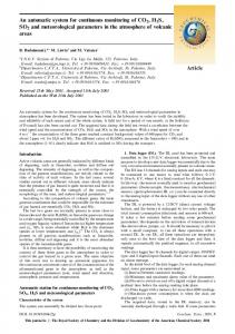
Figure I. Circuit for control of microdrive motor. each other as a dual astable multivibrator. The on-off sequence is initiated by depressing Pushbutton Switch S2.
Behavior Research Methods & Instrumentation 1980, Vol. 12(4),487-488
NOTE An integrated circuit for stepwise or continuous microdrive advancement MATTHEW A. LAITINEN, MICHAEL L. WOODRUFF, and RONALD H. BAISDEN College ofMedicine, East Tennessee State University, Johnson City, Tennessee 37614
A circuit for inexpensive automation of a hydraulic microdrive is described. The circuit uses two integrated timing circuits with output periods defined by resistancecapacitance circuits. The output of this circuit operates a relay that controls a small electric motor that runs the microdrive. This system can operate in either a continuous mode for long-term infusion of solutions or in a stepwise fashion for lowering electrodes. When attached to an appropriate microdrive, the circuit can be employed in experiments in which brain-behavior relationships are investigated within anatomical, pharmacological, or electrophysiological paradigms. Microdrive units have many applications in research directed toward elucidation of the relationship between various physiological parameters and behavior. Such units can be used to lower electrodes for recording various types of behavior-related neuronal potentials or, when attached to appropriate in-dwelling cannulas, for infusion of substances into either the brain or the circulatory system. Some units (e.g., Trent-Wells Model 3-0590) are not constructed with the necessary motor and control circuitry for automated and timed operation. Other units have the circuitry and motor for automated advancement but are comparatively expensive (e.g., Kopf ModeI607WCP, 1980 price: $4,235; Stoelting Company Standard Model 51422, 1980 price: $3,475). The system described in this note provides a low-cost electronic circuit that drives an inexpensive motor geared to a Trent-Wells Model 3-0590 hydraulic microdrive. Timing for the operation of the micro drive is controlled by two integrated circuits (ICs) independently controlled from external resistance-capacitance (RC) networks. The timing generated by these ICs individually can be varied from microseconds to minutes with great accuracy. Temperature stability is .005% per degree centigrade. For the combined circuit shown in Figure I, the timing is continuously variable from 2 to 20 sec. The timing circuits control the rate of the hydraulicmicrodrive driving motor by means of a relay. The circuit operates in the following manner. When Switch SI is in the PULSE position, stepwise operation of the microdrive is produced by Timing Circuits IC1 and IC2, which determine the off and on periods of Relay K1 (see Figure 1). le 1 and IC2 are connected to
Copyright 1980 Psychonomic Society, Inc.
each other as a dual astable multivibrator. The on-off sequence is initiated by depressing Pushbutton Switch S2. Momentary closing of S2 produces a negative-going pulse that triggers IC2 Input Pin 2. This causes IC2 Output Pin 3 to change from low to high for a time period defined by the values of R4, R5, and C4. At the end of this time period, the IC2 output goes from high to low and triggers ICI Input 2. ICl Output Pin 3 will then go from low to high for a predetermined time, which is defined by RI, R2, and Cl. When the output time for ICI is completed, the output goes to low and starts IC2. The cycle will repeat until stopped by the user. Timing Circuit IC2 determines the on time of Relay KI, and ICI determines the off time. The LED indicator light Dl is on whenever the relay Kl is operated. Continuous operation of Relay Kl, and therefore, the microdrive motor, can be produced by turning Switch SI to the CONT position. The power for the circuit is derived from a +12-V dc regulated power supply that is operated from 110 V ac introduced through Transformer TL The 12-V ac secondary output is rectified by a full-wave rectifier D3-D6 and filtered by Capacitor C9. An unregulated direct current of approximately 18 V is produced and fed into the +12-V de regulator IC3. All of the components depicted in Figure 1 are readily available from electronics suppliers and are very inexpensive. The total cost of the circuit was less than $50 (1980 prices). A list of the necessary components is given in Table I. Output of the circuit serves to regulate current flow to an electric motor that is geared to a Trent-Wells hydraulic microdrive. The circuit is +12V R1
t.
R2
..•. 7
C
"-;l
~IIOVAC ca
_6
It~
t
~R6 4a 2 3
T
6C7
+12V R7 +12V
~
I
'
J
it
I:-
FI
motor
I
5 C5
C4
to mIcrodrive
83
+12V
IOVAC~~_I~~I~~ Figure I. Circuit for control of microdrive motor.
487
0005-7878/80/040487-02$00.45/0
488
LAITINEN, WOODRUFF, AND BAISDEN Table 1 A List of Components
Cl, C4 Capacitor 10 microfarad 25 V de C2, C5 Capacitor .0012 microfarad C3, C6 Capacitor .01 microfarad C7 Capacitor .1 micro farad C8 Capacitor 600 picofarad C9 Capacitor 250 microfarad 50 V dc D1 Diode LED D2-06 Diode IN4759 F1 Fuse AGC .5 A IC1, IC2 Timing Circuit MC1455 IC3 Voltage Regulator +12 V MC7812 K1 Relay 12 V de R-1O-E2-Y4-V185 (potter and Brumfield) Ll Lamp Assembly 120 V ac RI, R4 Potentiometer 1 megohm Linear R2, R5 Resistor 100 kohm ± 5% .25 W R6, R7 Resistor 27 kohm ± .25 W R3 Resistor 470 ohm ± .25 W SI Switch SPDT Center Off S2 Switch PBDT S3 Switch SPST ri Transformer-Calectro Dl-746 12 V ac .5 A
enclosed, and the microdrive is mounted on Plexiglas. The motor we use turns at 1 rpm and is manufactured by the Cramer Division of the Conrac Corporation. The motor is Type 117 and runs on 115 Vac. Similar motors
with rpm values from .0004 to 20 are also available from Razel Scientific Instruments, P.O. Box 4054, Stamford, Connecticut 06907. The motors cost approximately $5 each. The 1980 price of the Trent-Wells 3-0590 standard hydraulic microdrive is $855. Inclusion of this commercial microdrive brings the entire unit cost to about $950, but the system can perform all of the operations of devices costing from $3,000 to $4,200. This system has been used for intracranial injection of less than a microliter of horseradish peroxidase or 6hydroxydopamine (Woodruff & Baisden, 1980) through a Hamilton microsyringe. It can also be used for intravenous infusion of much larger volumes.
REFERENCE M. 1., & BAISDEN, R. H. Increased catecholamine fluorescence in the anterior commissure of the rat induced by intraseptaI6-hydroxydopamine. Anatomical Record, 1980, 196, 255A.
WOODRUFF,
(Received for publication August 6, 1980; accepted August 8,1980.)