Original Article International Journal of Fuzzy Logic and Intelligent Systems Vol. 18, No. 1, March 2018, pp. 20-28 http://doi.org/10.5391/IJFIS.2018.18.1.20
ISSN(Print) 1598-2645 ISSN(Online) 2093-744X
An Integrated Fault Detection and Identification System for Permanent Magnet Synchronous Motor in Electric Vehicles Ali Rohan1 , Mohammed Rabah1 , and Sung Ho Kim2 1 School
of Electronics and Information Engineering, Kunsan National University, Gunsan, Korea of Control and Robotics Engineering, Kunsan National University, Gunsan, Korea
2 Department
Abstract This paper proposes an efficient and integrated fault detection and identification system for power converters and permanent magnet synchronous motor in electric vehicles. Switching faults of power converters (single, double and triple switching faults), electrical and mechanical faults of the permanent magnet synchronous motor (bearing fault, stator electrical faults) are considered. Fault detection is done using Clarke transformed (α-β) three-phase current analysis. Features are extracted from the current signals and artificial neural network (ANN) is used for the fault identification. Using motor current signature analysis and by selecting simple and suitable features, the system can detect and distinguish between overall faults of power converters and permanent magnet synchronous motor in an electric vehicle; it requires no complex calculations. The proposed system is designed in MATLAB/Simulink. The system is tested under different fault scenarios and performance is evaluated. The simulation results have proved that the proposed system can detect and identify overall faults of power converters and permanent magnet synchronous motor easily and effectively with no need for complex calculations and techniques. Keywords: Stator current analysis, Feature extraction, Fault detection and identification, Switching faults, Motor faults, Permanent magnet machine, Artificial neural network
1. Received: Feb. 27, 2018 Revised : Mar. 12, 2018 Accepted: Mar. 20, 2018 Correspondence to: Sung Ho Kim (
[email protected]) ©The Korean Institute of Intelligent Systems
cc
This is an Open Access article distributed under the terms of the Creative Commons Attribution Non-Commercial License (http://creativecommons.org/licenses/ by-nc/3.0/) which permits unrestricted noncommercial use, distribution, and reproduction in any medium, provided the original work is properly cited.
Introduction
In recent times with an increasing need for energy conservation and emission reduction, electric vehicles are considered as the best transportation source instead of typical vehicles. Electric vehicles basically comprise of a motor drive system that is used to convert electrical energy into mechanical energy. A typical motor drive system is based on power converters and an electric motor. Power converters provide regulated electrical power to the motor through batteries or some other energy source. In electric vehicle system, different types of electric motors can be used such as induction motors, brushless DC motors, and permanent magnet synchronous motors (PMSM). In contrast to other types of motor, PMSM is considered as the best option due to its advantages of high power density and high efficiency [1–3]. As the electric vehicle system is based on power converters and electric motor, there is always a chance of system failure which might be due to some faults in power converters or
| 20
International Journal of Fuzzy Logic and Intelligent Systems, vol. 18, no. 1, March 2018
electric motor. The main faults caused by power converters are switching faults that occur due to an open or short circuit in an insulated-gate bipolar junction transistor (IGBT) device. The fault caused by electric motor could be an electrical or mechanical fault. The electrical fault of the motor might occur due to any of the following: an open circuit in one of the three-phase power line, a short circuit between the two or more coils in the stator winding, and a short circuit between windings of the same coils called as the inter-turn short circuit fault. The mechanical fault in case of PMSM might be due to a faulty bearing, air gap flux difference, rotor eccentricity, shaft misalignment, or mass unbalance. For a reliable and smooth operation of the system, it is required to detect these faults early to avoid a total system failure. In past, different studies about design, control, and problems of motors have been conducted [4–8]. Several authors proposed different techniques to tackle this kind of problems. In [9], a fault diagnosis and monitoring system using Kohonen neural network was proposed. For identification of rotor faults an online diagnosis method using flux signals was described in [10]. A method to detect and diagnose serial wound starter motor faults using suitable features by a feedforward multilayer neural network was presented in [11]. Fuzzy logic-based fault detection system was developed for implementation on emergency vehicles in [12]. In [13], the authors evaluated wavelet-based schemes based on neural network and support vector machine (SVM) for bearing fault detection and classification. An artificial neural network (ANN)-based fault diagnosis system for PMSM using feedforward neural network for short circuit faults in stator windings was presented [14]. Authors detected faults in switched reluctance motor using the Kohonen neural network [15]. The discrete wavelet transform (DWT) based feature extraction method for switching fault detection was proposed in [16]. Another work on inverter switching faults using neural network was proposed in [17].
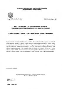
Figure 1. Structure of fault detection and identification system.
ical) for PMSM in an electric vehicle. The proposed system works on the motor current signature analysis method. By just analyzing the three-phase current of the motor and using simple features, the proposed system works efficiently to detect and identify the faults without any need of extensive feature extraction and complex calculations. The proposed fault detection and identification system is designed in MATLAB/Simulink and simulations are carried out under different fault scenarios. The result shows that the proposed system is efficient and simple enough to detect and identify the faults for PMSM in an electric vehicle. This paper is divided into following sections: Section 1 provides an introduction; Section 2 describes the structure of fault detection and identification system; Section 3 contains the simulation studies and results; and Section 4 outlines the conclusion.
2.
Structure of Fault Detection and Identification System
All these fault detection methods were designed to detect some specific types of fault; these fault detection methods can detect either an electrical fault or mechanical fault but are not good enough to act as an integrated method to completely detect and classify the faults. Some are good enough to detect electrical faults and can distinguish the fault types but they cannot detect mechanical faults.
Structure of fault detection and identification system is shown in Figure 1. An electric vehicle system based on PMSM is developed using the vehicle dynamics implemented in [18]. MATLAB/ Simulink is used to design and implement the proposed algorithm. Initially, three-phase motor current is converted to two-phase (α-β) using Clarke transformation and features are extracted from the Clarke transformed current pattern.
In cases when some are efficient enough to detect mechanical faults, they, however, fail to detect electrical faults. In this work, an integrated fault detection system is developed to efficiently detect and classify the fault types (both electrical and mechan-
These features are given as an input to a neural network that computes the output on the basis of the training data.
21 | Ali Rohan, Mohammed Rabah, and Sung Ho Kim
http://doi.org/10.5391/IJFIS.2018.18.1.20
(a)
(b)
Figure 2. Block diagram of PMSM control system. 2.1
Figure 3. Block diagram of controller: (a) outer control loop and (b) inner control loop.
PMSM Control
The proposed system comprises of a PMSM driven by an inverter. Figure 2 shows the control mechanism used to operate the PMSM. In case of an electric vehicle, the main source of power is batteries. Batteries provide DC power regulated by a DC/DC converter and this regulated DC power is converted to threephase controlled AC using a three-phase inverter to operate the motor. In order to control the PMSM operation, vector control technique is implemented. The control technique comprises of two loops of operation: 1) Outer control loop (speed controller). 2) Inner control loop (current controller or vector controller). The outer control loop works by taking the motor output speed ωl and speed reference ωref as inputs and gives torque reference Te ∗ as an output. A PI controller is used to control the operation of the system. Torque reference generated by the outer speed control loop is given as an input to the inner control loop. The torque reference is converted to three-phase current reference using d − q transformation and compared with the motor three-phase current to generate the gate driving pulses. Eq. (1) was used to convert reference torque to current. Te ∗ =
3 np [λm iq + (Ld − Lq ) id iq ] . 2
(1)
The block diagram of the control system is shown in Figure 3. 2.2
Feature Extraction and Neural Network System
Features are extracted from the Clarke transformed (α-β) current patterns. The selection of feature plays an important role in the efficiency of the fault detection system. Features were www.ijfis.org
selected carefully to decrease the computation time and increase the efficiency of the fault detection system. The extracted features are mean, standard deviation and angle, and are given as: P Iα , (2) Iα = n P Iβ , (3) Iβ = n s P 2 (Iα − Iα ) σ Iα = , (4) n s P 2 (Iβ − Iβ ) σ Iβ = , (5) n ! Iβ θ = atan , (6) Iα where, Iα and Iβ is the Clarke transformed two-phase current signal along (α-β) axis, Iα and Iβ is the mean, σIα and σIβ is the standard deviation, and θ is the angle between the two axis. Figure 4 shows the basic coordinate system for Clarke transformation. Extracted features are used to train the neural network. A feedforward network-based ANN is used to identify the faults. The proposed neural network is based on an input layer with 5 neurons, one hidden layer, and one output layer with 16 neurons corresponding to the number of detected faults. The target output of the system was 1 in case of any fault. The target output for a normal case would be as follows: Target Output = [1 0 0 0 0 0 0 0 0 0 0 0 0 0 0 0],
(7)
where 1 represents the faulty condition and 0 represents that
An Integrated Fault Detection and Identification System for Permanent Magnet Synchronous Motor in Electric Vehicles
| 22
International Journal of Fuzzy Logic and Intelligent Systems, vol. 18, no. 1, March 2018
air gap flux difference the flux linkage of the motor is changed and the fault is created. Using motor current signature analysis, three-phase current of the motor is monitored under different fault scenarios. This three-phase current is converted to two-phase using Clarke transformation and features are extracted. Extracted features are given as an input to neural network and faults are detected. Figure 6 shows the Simulink model for the fault identification system. 3.2 Figure 4. Three-phase to (α-β) coordinate system for Clarke transformation. currently there is no fault.
3.
Simulation Studies
The proposed fault detection and identification system was modeled in MATLAB/Simulink. The Simulink model of the system is shown in Figure 5. 3.1
Fault Categorization and Implementation
The system is tested under 16 different fault scenarios including both electrical and mechanical faults. The electrical faults are the following: short circuit fault caused by a short circuit between any of the three phases; open circuit fault caused by an open circuit in any of the three phases; and inverter switching faults caused by a short or open circuit in any of the switching devices. Further, the inverter switching faults are classified into single, double, and triple switching faults caused by a short or open circuit in a single or multiple switching devices. The mechanical faults are bearing fault caused by the faulty bearing and air gap flux difference fault caused by the difference in the air gap flux in the motor. For short circuit electrical faults, a short circuit between the two phases is made by using a resistance of very small value. Whereas, in case of open circuit faults, the fault is implemented by disconnecting one of the three phases. Inverter switching faults are implemented by creating a short circuit or an open circuit by using the resistance of small and high values, respectively. In order to implement the mechanical faults, such as bearing and air gap flux difference fault, changes in the parameters of the motor are made. In case of faulty bearing the friction caused by the bearing will be high; and by changing the friction coefficient of the motor, this fault is implemented. For 23 | Ali Rohan, Mohammed Rabah, and Sung Ho Kim
Results
It can be seen from the Figure 7 that every fault gives a pattern that differs from the normal case. In the normal case the output is a complete circle, but in case of a fault the output is biased with some specific pattern. By monitoring these fault patterns and extracting the features, faults are distinguished. Figure 8 shows the results obtained on the output of the neural network. In case of normal fault the output values will be 0 but in case there is a fault the neural network will give the output as 1. By observing the output value of the neural network, faults can be identified easily. The proposed fault detection and identification system is tested for each fault mentioned before and simulations are carried out to test the performance of the system. The system is able enough to detect and identify single as well as multiple faults. The accuracy of the proposed system is 100% and results clearly show that the system is able enough to detect and identify faults effectively and efficiently. 3.3
Performance Evaluation and Comparative Study
Performance evaluation of the proposed technique is done by comparing it with some previously implemented techniques for fault detection and identification such as Technique 1 in [17] and Technique 2 in [16]. All the techniques are implemented in MATLAB/Simulink and simulations are carried out repeatedly to get the results. Output results show that proposed technique is much better in comparison to Techniques 1 and 2 as it can detect single, double and triple switching faults, inter-turn short circuit fault and mechanical faults with 100% accuracy in one cycle period of output current or voltage. Table 1 shows the detected faults and description. Using Technique 1 [17], the system shows high accuracy in single and double switching faults but 95% accuracy in case of triple switching faults and inter-turn short circuit fault, due to less number of features to differentiate the faults. For mechani-
http://doi.org/10.5391/IJFIS.2018.18.1.20
Figure 5. Simulink model for the overall system. Table 1. Detected faults and description Fault AB short BC short AC short Figure 6. Simulink model for fault identification system: feature extraction and neural network.
Bearing fault
S3
In the case of Technique 2 [16], the system shows high accuracy in single and double switching faults but triple switching fault and inter-turn short circuit fault accuracy is nearly 70% and for mechanical faults 85% due to the similarity of feature data in such complex case. The reason behind its slow detection is the complex method to identify and detect the faults. www.ijfis.org
Fault due to the short or open circuit between two phases Inter-turn short circuit Fault due to faulty bearing in motor
S1 S2
cal faults, the accuracy of the system is 90%. The reason behind this issue is that in case of triple switching faults, inter-turn short circuit faults and mechanical faults, two-dimensional pattern similarity is high and we have a small number of features to identify the specific switch fault. Therefore, the neural network is unable to identify the specific fault due to many similar data and mix up the fault type in the end. The number of features used is 9.
Fault description
S4 S5
Single switching fault due to the open or short circuit in one switching device in an electrical drive
S6 S1 & S4 S2 & S5 S1 & S4 & S6 S2 & S3 & S5 Air gap flux diff.
Double switching fault due to the open or short circuit in two switching devices in an electrical drive Triple switching fault due to the open or short circuit in three switching devices in an electrical drive Fault due to difference in the flux linkage
In this technique, the number of features used is 13. Initially, DWT is used to extract the features in separate file due to the
An Integrated Fault Detection and Identification System for Permanent Magnet Synchronous Motor in Electric Vehicles
| 24
International Journal of Fuzzy Logic and Intelligent Systems, vol. 18, no. 1, March 2018
Figure 7. Fault pattern of the Clarke transformed current signals.
Figure 8. Output results for different fault conditions. system complexity and these features are saved in MATLAB workspace. Then in the separate Simulink file, these features are used to detect and identify the faults using a neural network. Likewise in a real system, this data similarity while detection or dissimilarity with the trained neural network can happen due to random noise or other environmental uncertainties. In the case of proposed fault detection and identification technique, the system shows very high accuracy in single, double and triple switching faults, inter-turn short circuit faults and mechanical faults. The number of features used is 5. The system takes less computational and detection time with independent features for all types of faults. Table 2 shows the comparison between the
25 | Ali Rohan, Mohammed Rabah, and Sung Ho Kim
proposed Techniques 1 and 2.
4.
Conclusion
An effective and efficient method to detect and identify the faults for PMSM in an electric vehicle system has been proposed in this work. MATLAB/Simulink is used to model and implement the proposed method. The system works on the motor current signature analysis phenomenon with the ANN based fault detection and identification technique. The system is tested for electrical as well as mechanical faults. The simulation results show that the proposed fault detection and identification
http://doi.org/10.5391/IJFIS.2018.18.1.20
Table 2. Comparison of proposed and previous techniques Fault
Technique 1 Accuracy Response (%) time
No. of features
Technique 2 Accuracy Response (%) time
No. of features
Proposed technique Accuracy Response No. of (%) time features
AB short BC short
95
70
AC short Bearing fault S1
90
85
100
S2 S3
100
Medium
9
100
Medium
13
100
Fast
5
S4 S5 S6 S1 & S4 S2 & S5 S1 & S4 & S6 S2 & S3 & S5 Air gap flux diff.
95
90
100
95
70
100
90
85
100
system is able enough to identify the faults for PMSM in an electric vehicle system.
Conflict of Interest No potential conflict of interest relevant to this article was reported.
References [1] K. D. Hoang, Y. Ren, Z. Q. Zhu, and M. Foster, “Modified switching-table strategy for reduction of current harmonics in direct torque controlled dual-three-phase permanent magnet synchronous machine drives,” IET Electric Power Applications, vol. 9, no. 1, pp. 10-19, 2015. https://doi.org/10.1049/iet-epa.2013.0388 [2] R. Islam, M. Islam, J. Tersigni, and T. Sebastian, “Inter winding short circuit faults in permanent magnet synchronous motors used for high performance applications,” in Proceedings of the 4th Annual IEEE Energy Conversion Congress and Exposition, 2012, pp. 1291-1298. https://doi.org/10.1109/ECCE.2012.6342667 www.ijfis.org
[3] G. Vinson, M. Combacau, T. Prado, and P. Ribot “Permanent magnets synchronous machines faults detection and identification,” in Proceedings of the 38th Annual Conference on IEEE Industrial Electronics Society, Montreal, Canada, 2012, pp. 3925-3930. https://doi.org/10.1109/ IECON.2012.6389265 [4] K. R. Weeber, M. R. Shah, K. Sivasubramaniam, A. ElRefaie, R. Qu, C. Stephens, and S. Galioto, “Advanced permanent magnet machines for a wide range of industrial applications,” in Proceedings of IEEE Power and Energy Society General Meeting, Providence, RI, 2010, pp. 1-6. https://doi.org/10.1109/PES.2010.5590104 [5] S. M. A. Cruz and A. J. M. Cardoso, “Multiple reference frames theory: a new method for the diagnosis of stator faults in three-phase induction motors,” IEEE Transactions on Energy Conversion, vol. 20, no. 3, pp. 611-619, 2005. https://doi.org/10.1109/TEC.2005.847975 [6] D. Diallo, M. E. H. Benbouzid, D. Hamad, and X. Pierre, “Fault detection and diagnosis in an induction machine drive: a pattern recognition approach based on Concordia stator mean current vector,” IEEE Transactions on Energy
An Integrated Fault Detection and Identification System for Permanent Magnet Synchronous Motor in Electric Vehicles
| 26
International Journal of Fuzzy Logic and Intelligent Systems, vol. 18, no. 1, March 2018
Conversion, vol. 20, no. pp. 512-519, 2005. https://doi. org/10.1109/TEC.2005.847961 [7] M. Sahraoui, A. Ghoggal, S. E. Zouzou, A. Aboubou, and H. Razik, “Modelling and detection of inter-turn short circuits in stator windings of induction motor,” in in Proceedings of the 32nd Annual Conference on IEEE Industrial Electronics, Paris, France, 2006, pp. 4981-4986. https://doi.org/10.1109/IECON.2006.348093 [8] J. O. Estima and A. J. M. Cardoso, “A new algorithm for real-time multiple open-circuit fault diagnosis in voltagefed PWM motor drives by the reference current errors,” IEEE Transactions on Industrial Electronics, vol. 60, no. 8, pp. 3496-3505, 2013. https://doi.org/10.1109/TIE.2012. 2188877 [9] B. S. Yang, T. Han, and J. L. An, “Art-Kohonen neural network for fault diagnosis of rotating machinery,” Mechanical Systems and Signal Processing, vol. 18, no. 3, pp. 645657, 2004. https://doi.org/10.1016/S0888-3270(03)000736 [10] M. Bouzid, G. Champenois, N. Bellaaj, and K. Jelassi, “Automatic and robust diagnosis of broken rotor bars fault in induction motor,” in Proceedings of the IEEE 19th International Conference on Electrical Machines, Rome, Italy, 2010, pp. 1-7. https://doi.org/10.1109/ICELMACH. 2010.5608108 [11] R. Bayir and O. F. Bay, “Serial wound starter motor faults diagnosis using artificial neural network,” in Proceedings of the IEEE International Conference on Mechatronics, Istanbul, Turkey, 2004, pp. 194-199. https://doi.org/10. 1109/ICMECH.2004.1364436 [12] R. Bayir and O. F. Bay, “A fault diagnosis of engine starting system via starter motors using fuzzy logic algorithm,” Gazi University Journal of Science, vol. 24, no. 3, pp. 437-449, 2011 [13] G. S. Vijay, H. S. Kumar, P. P. Srinivasa, N. S. Sriram, and R. B. K. N. Rao, “Evaluation of effectiveness of wavelet based denoising schemes using ANN and SVM for bearing condition classification,” Computational Intelligence and Neuroscience, vol. 2012, article no. 16, 2012. https://doi.org/10.1155/2012/582453 [14] S. S. Moosavi, A. Djerdir, Y. Ait-Amirat, and D. A. Khaburi, “ANN based fault diagnosis of permanent mag27 | Ali Rohan, Mohammed Rabah, and Sung Ho Kim
net synchronous motor under stator winding shorted turn,” Electric Power Systems Research, vol. 125, pp. 67-82, 2015. https://doi.org/10.1016/j.epsr.2015.03.024 [15] A. Uysal and R. Bayir, “Real-time condition monitoring and fault diagnosis in switched reluctance motors with Kohonen neural network,” Journal of Zhejiang University Science C, vol. 14, no. 12, pp. 941-952, 2013. https://doi. org/10.1631/jzus.C1300085 [16] A. Rohan and S. H. Kim, “Fault detection and diagnosis system for a three-phase inverter using a DWT-based artificial neural network,” International Journal of Fuzzy Logic and Intelligent Systems, vol. 16, no. 4, pp. 238-245, 2016. https://doi.org/10.5391/IJFIS.2016.16.4.238 [17] M. Talha, F. Asghar, and S. H. Kim, “A Matlab and Simulink based three-phase inverter fault diagnosis method using three-dimensional features,” International Journal of Fuzzy Logic and Intelligent Systems, vol. 16, no. 3, pp. 173-180, 2016. https://doi.org/10.5391/IJFIS. 2016.16.3.173 [18] A. Rohan, F. Asghar, and S. H. Kim, “Design of fuzzy logic tuned PID controller for electric vehicle based on IPMSM using flux-weakening,” Journal of Electrical Engineering and Technology, vol. 13, no. 1, pp. 451-459, 2018. https://doi.org/10.5370/JEET.2018.13.1.451 Ali Rohan received his B.S. degree in Electrical Engineering from The University of Faisalabad, Pakistan in 2012. Currently, pursuing his M.S. and Ph.D. in Electrical, Electronics and Control Engineering from Kunsan National University, Korea. His research interests includes renewable energy system, power electronics, fuzzy logic, neural network, EV system, flywheel energy storage system. E-mail: ali
[email protected] Mohammed Rabah received his B.S. degree in Electronics and Telecommunication Engineering from the AL-SAFWA High Institute of Engineering, Cairo, Egypt in 2015. He completed his M.S. in Electrical, Electronics and Control Engineering from Kunsan National University, Gunsan, Korea in 2017. Currently, pursuing his Ph.D. in Electrical, Electronics and Control Engineering from Kunsan National University, Korea. His research interests includes UAV’s, fuzzy
http://doi.org/10.5391/IJFIS.2018.18.1.20
logic systems and machine learning. E-mail:
[email protected] Sung Ho Kim received his B.S. degree in Electrical Engineering from Korea University in 1984. He completed his M.S. and Ph.D. in electrical engineering from Korea Univer-
www.ijfis.org
sity in 1986 and 1991 respectively. In 1996, he completed his Postdoc from Hirosima University in Japan. Currently, he is a professor at Kunsan National University. His research interests includes fuzzy logic, sensor networks, neural networks, intelligent control system, renewable energy system, fault diagnosis system. E-mail:
[email protected]
An Integrated Fault Detection and Identification System for Permanent Magnet Synchronous Motor in Electric Vehicles
| 28