Abstractâ In this paper, an Integrated Radio Resource. Allocation (IRRA) framework is proposed for enhanced uplink. UTRA-FDD with fixed relay stations ...
An Integrated Radio Resource Allocation Framework for Enhanced Uplink UTRA-FDD with Fixed Relay Stations Yajian Liu, Reza Hoshyar, Xinjie Yang, Rahim Tafazolli Center for Communication Systems Research (CCSR), University of Surrey Guildford, GU2 7XH, UK Y.Liu {R.Hoshyar, Xinjie.Yang, R.Tafazolli}@eim.surrey.ac.uk Abstract— In this paper, an Integrated Radio Resource Allocation (IRRA) framework is proposed for enhanced uplink UTRA-FDD with fixed relay stations (FRSs). It comprises two entities: Relaying Link Scheduler (RLS), and Transmission Mode Aware Packet Scheduler (TMAPS). RLS is responsible for the scheduling of user transmission modes (direct or relaying) and routes, whereas TMAPS is responsible for the scheduling of user transmission time and rates. These two entities operate synchronously, periodically, and with coordinated interactions. System level simulation results show that this framework is able to ensure significant gains in terms of cell throughput. Keywords- Relaying Link Scheduler (RLS), Packet Scheduler (PS), Multi-hop, Uplink, UTRA-FDD
I. INTRODUCTION In recent years, in order to improve the capacity and coverage of cellular systems, a new system concept, multi-hop cellular network (MCN), is getting more and more attention [1]-[6]. Due to the capability of reducing overall path attenuations, and thus, decreasing transmission power and interference level, multi-hop concept does open a door for the performance improvements of cellular systems. However, it has its own inherent drawbacks, such as requiring extra radio resources for relaying hops, very sensitive to the quality of relaying routes etc. Hence, multi-hop does not always lead to performance improvements. Only with well-designed radio resource management (RRM) algorithms, performance gains could be achieved with reasonable costs. So far, lots of research work has been done on the investigation of the RRM algorithms for MCNs. Some approaches have been proposed for finding out when to resort relaying, such as reach-ability-based scheme [2], and distancebased scheme [1][3] etc. Various algorithms have been proposed for the relay station selection, such as distance-based routing, pathloss-based routing [4], and power-based routing [5] etc. And some simple resource allocation approaches have been studied in [6]. Although, [1]-[6] show that the coverage and capacity of cellular systems could be improved by using relaying, the strategy for effectively coordinating routing, packet scheduling and relay station load balancing within an integrated framework has not been investigated. In this paper, an Integrated Radio Resource Allocation (IRRA) framework is proposed. It comprises two entities: the first one, named Relaying Link Scheduler (RLS), is for the scheduling of user transmission modes and routes, whereas the second entity, named Transmission Mode Aware Packet
Scheduler (TMAPS), is for the scheduling of user transmission time and rates. The two entities operate synchronously, periodically, and with coordinated interactions. System level simulation results show that this framework is able to ensure significant gains in terms of cell throughput. The rest of the paper is organized as follows: in section II, the system scenario is described. The proposed IRRA framework is presented in detail in section III. In section IV, system level simulation results are demonstrated and discussed. Finally, this paper is concluded in section V. II.
SYSTEM SCENARIO: ENHANCED UPLINK UTRA-FDD WITH FIXED RELAY STATIONS
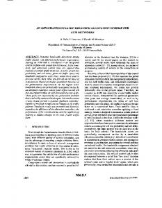
A. Introduction In our study, the enhanced uplink UTRA-FDD [7] is employed as the basis, and then fixed relay stations (FRSs) are introduced to build a type of MCN as our system scenario. The cell layout is hexagonal grid with 3 tiers. An example of cell deployment is shown in Fig.1.
Figure 1. Enhanced uplink UTRA-FDD with fixed relay stations
Fixed relay stations are assumed to be located on the perimeter of a circle symmetrically. The cell radius is denoted as R, the distance between the BS and each RS is denoted as r. It is assumed that from users to the BS, maximally two hops could be used, and in order not to highly increase the complexity of BSs and RSs etc., both these two hops employ WCDMA/FDD (rather than use heterogeneous air-interfaces), but different carrier frequencies are adopted to avoid the selfinterference of RSs. Note that most network operators have licenses for more than one carrier frequencies, hence above assumption is implementation feasible. B. Resource allocation of enhanced uplink UTRA-FDD The resource allocation in enhanced UTRA-FDD is mainly managed by NodeB (BS) packet scheduler [7], which is one of
the major enhancements against the uplink of other UMTS versions (which use RNC packet scheduler) for the purpose of fast resource scheduling. NodeB packet scheduler operates periodically. At each scheduling instant, it issues resource assignments to users based on available cell capacity, user priorities and user needs etc. The assignments are valid till the next scheduling instant, when new assignments will be issued. Normally, a resource assignment for a user indicates whether this user is allowed to transmit in the next scheduling period and what is the available TFC (Transport Format Combination) subset for this user. Note that each TFC corresponds to a certain transmission data rate. Above mechanism could be regarded as a two-dimension resource allocation for “transmission time” and “transmission rate”. Noteworthy, the allocation of spreading codes is not considered in enhanced uplink UTRA-FDD due to the fact that each user has a uniquely assigned scrambling sequence, thus the spreading code resources occupied by each user do not affect those available for others. More details about the NodeB scheduling algorithms for enhanced uplink UTRA-FDD can be found in [7] and [9]. C. Interference issues of enhanced uplink UTRA-FDD SIR (signal-to-interference ratio) is a very important indicator for the quality of data receiving. To maintain a certain user QoS (for instance: a certain Block Error Rate), a particular SIR value needs to be maintained at the receiver given a certain radio channel condition. In enhanced uplink UTRA-FDD, this SIR value is maintained by closed-loop power control. The load factor of a user is a function of the SIR at the BS, as shown in following equation: Prx , MSi � BS
K MS � BS i
Prx , MSi � BS I total , BS
I total , BS � Prx , MSi � BS Prx , MSi � BS 1� I total , BS � Prx , MSi � BS
SIRMSi � BS
(1)
1 � SIRMSi � BS
KMSi-BS is the load factor of user i at the BS. Prx,MSi-BS is the received power of user i at the BS. Itotal,BS is the total interference at the BS. SIRMSi-BS is the SIR of user i at the BS. Due to the existence of closed-loop power control, in enhanced uplink UTRA-FDD, the load factor of user i at the BS could be approximated as follows:
K MS � BS | i
SIRt arg et ,MSi � BS
(2)
1 � SIRt arg et ,MSi � BS
SIRtarget,MSi-BS is the power control SIR target of user i. For different transmission rates, power control SIR targets are different, and thus different load factors will be induced at the BS. Then, based on equation (1) and (2), we can derive the following equation for the packet scheduler to estimate how much extra cell capacity will be taken if a new rate is given to a user:
K diff , MS � BS | i
SIR new t arg et ,MSi � BS 1 � SIR new t arg et ,MSi � BS
�
SIR MSi � BS
(3)
1 � SIR MSi � BS
In relay-based systems, equation (3) could still be applicable for direct transmission links, but not for multi-hop links. In next section when presenting the algorithm for TMAPS, the load estimation for multi-hop links will be discussed. III.
INTEGRATED RADIO RESOURCES ALLOCATION (IRRA)
A.
Introduction In enhanced uplink UTRA-FDD with fixed relay stations, a three-dimension resource allocation is envisioned for “transmission time”, “transmission rate”, and “transmission mode and route”. Noteworthy, the transmission mode and route are considered together as one dimension since they are coupled with each other. To fulfill above resource allocation task, we propose an Integrated Radio Resource Allocation (IRRA) framework, which comprises two entities: the first entity, named Relaying Link Scheduler (RLS), is mainly for the scheduling of user transmission modes and routes, and it includes four main functions: Best Relaying Route Calculation (BRRC), Candidate List Generation (CLG), Priority Management (PM), and Relay Station Load Balancing (RSLB); The second entity, named Transmission Mode Aware Packet Scheduler (TMAPS), is for the scheduling of user transmission time and rates. These two entities operate synchronously, periodically, and with coordinated interactions. The major advantages of the proposed framework lie in the following aspects: firstly, by synchronizing and coordinating RLS and TMAPS, an appropriate set of users can be easily worked out for relaying transmissions without overloading relay stations or underutilizing the chances to relay users, in addition, the potential load reductions due to relaying transmissions can be promptly translated into increases on user assigned rates, which directly lead to throughput improvements. Furthermore, by performing RLS and TMAPS periodically, the resource allocation for “transmission time” “transmission rate” and “transmission mode and route” can promptly adapt to system dynamics, such as traffic burstiness and session comings or leavings etc. B. Structure and procedures IRRA resides in the BS. As shown in Fig. 2, its main inputs are end-to-end transmission losses, interference/load levels at the BS and RSs, user queue sizes, and user power-limited max rates (the max rates that users could support given their power limits). The major outputs of IRRA are “transmission time”, “transmission rate” and “transmission mode and route” for individual users. IRRA operates periodically, and for each operation, the procedure is as follows: 1) The first two functions of RLS: BRRC and CLG, are executed to work out tentative user transmission modes and routes, and then output them to TMAPS;
2) TMAPS performs packet scheduling and then feeds back tentative user transmission time and rates to RLS; 3) The last two functions of RLS: PM and RSLB, are executed to work out fine-tuned user transmission modes, routes, and load-limited max rates (the max rates that users could reach given the load limits of RSs), and output them to TMAPS; 4) TMAPS performs packet scheduling once again to finetune user transmission time and rates, based on the updated user transmission modes, routes, and user load-limited max rates.
D. Relaying Link Scheduling (RLS) Considering the capacity of uplink UTRA-FDD is interference-limited, thus the most beneficial transmission mode or route for a user is the one inducing the least system interference/load, therefore, we introduce a criterion, namely Load Cost Indicator (LCI), for the assessment of user transmission modes and routes:
] MS � RS i
x
(4)
I total , RS x * LMSi � RS x
]MSi-RSx is the LCI of the route from user i to RS x. Itotal,RSx is total interference at RS x. LMSi-RSx is the end-to-end transmission loss from user i to RS x. The LCI of a direct transmission route could be calculated likewise. The reason for choosing above equation as LCI is shown in the following derivations, based on equation (1), (2), and (4): ] MS � RS i
I total , RS x * LMSi � RS x
x
Prx , MSi � RS x
K MS � RS i
Ptx , MSi
K MS � RS i
Figure 2. Structure and procedure of IRRA
It is worth mentioning that apart from the packet scheduling for users (the main task of TMAPS), the BS should also take care of the packet scheduling for RSs. Nevertheless, RSs are assumed to use direct transmission mode all the time and transmit with another carrier frequency, therefore, the packet scheduling for them could be performed independently with conventional algorithm, such as the PS algorithm in [9]. Hence, in the paper, we will not further discuss this issue. C. ETE transmission loss calculation End-to-end transmission loss is the summation of the gains and losses along the path from the transmitter to the receiver, including channel losses, antenna gains, cable losses etc. Basically, IRRA needs two types of end-to-end transmission losses as inputs: transmission losses between MSs and the BS, and transmission losses between MSs and their neighboring RSs. It is assumed that IRRA could get these endto-end transmission losses from a database, namely ETE transmission loss database. Due to the mobility of users, the database should be updated periodically. The period could equal to the IRRA period or a multiple of it. The detailed approaches and protocols for updating these transmission losses are beyond the scope of this paper. However, the following basic schemes could be considered: 1) neighbor probing mechanism proposed for ODMA [8]; 2) Approximate uplink losses with downlink losses, which could be measured and reported by users based on the received downlink pilot signal strength.
| Ptx , MSi * x
x
*
Ptx , MSi Prx , MSi � RS x
(5)
1 � SIRt arg et , MSi � RS x SIRt arg et , MSi � RS x
Note that the SIR target of a user normally is fixed given a certain user transmission rate, hence equation (5) indicates that the proposed LCI is proportional to the transmission power, i.e., the bigger the LCI is, the higher the transmission power is needed for delivering same amount of traffic, and thus the more interference is induced to the system. Therefore, the proposed LCI well reflects the load costs of user transmission routes. x
Best Relaying Route Calculation (BRRC)
The main task of BRRC is to calculate the best relaying route for all the users. In our work, the best relaying route of a user is defined as the route with the least LCI. x
Candidate List Generation (CLG)
CLG is responsible for generating a so-called candidate list that contains all the candidate users for relaying transmission. The following equation is employed in our work for the generation of candidate list:
i J , if ] MSi � BS ,dB � ] MSi � Best RS ,dB ! W
(6)
J is the candidate list. ]MSi-BS,dB is the LCI of the direct transmission route of user i in dB. ]MSi-Best RS,dB is the LCI of the best relaying route of user i in dB. W is the eligibility threshold in dB. After the candidate list is generated, the tentative user transmission modes and routes are determined: all the users in the candidate list are tentatively in relaying transmission mode using their best relaying routes, whereas all users outside candidate list are tentatively in direct transmission mode. Noteworthy, these tentative transmission modes and routes may be fine-tuned by the RSLB later on for the purpose of RS load balancing. x
Priority Management (PM)
The main task of PM is to prioritize users in order to indicate which users could bring more benefits to the system by using relaying transmission, thus should have priority to be relayed when relaying resources are limited. Considering that the capacity of uplink UTRA-FDD is interference-limited, LCI-based priority function is employed in this work, as follows:
xi
] MS � BS ,dB � ] MS � Best RS ,dB i
(7)
i
xi is the priority of user i, and the higher the xi is, the more benefits this user could bring to the system by using relaying transmission. x
Relay Station Load Balancing (RSLB)
RSLB is responsible for performing load balancing for RSs to prevent the overloading of them. To judge whether a RS is overloaded, the following criteria could be considered: 1) Number of relaying links at the RS; 2) Interference level at the RS. The former is normally used in the scenario where spreading codes or time slots etc. for relaying links are limited, and the latter is normally adopted in the scenario where the capacity of RSs are interference-limited. To relieve overloading, the following approaches could be considered: 1) Switch multi-hop users from overloaded RSs to under loaded RSs; 2) Switch multi-hop users back to direct transmission mode; 3) Reduce the rate of multi-hop users. The first two schemes are normally used when the number of relaying links per RS is limited, whereas the last scheme is normally employed when the interference level at the RS is limited. The overloading relief starts from the most heavily loaded RS, and for every RS, starts from the user with the least priority (user priorities are calculated with equation (7)). E. Transmission Mode Aware Packet Scheduler (TMAPS) TMAPS has similar procedure with the NodeB scheduling algorithm in [9]: firstly, the available cell capacity is estimated; then, users are prioritized based on a certain priority function; finally, transmission time and rate are assigned to individual users according to their priorities and needs, and available cell capacity. Noteworthy, in the final step, before a new rate is assigned to a user, load estimation needs to be performed to see how much extra cell capacity will be taken if the new rate is given to the user. The major enhancement of TMAPS against the NodeB scheduling algorithm in [9] is TMAPS employs different load estimation approaches for users in different transmission modes. For users in direct transmission mode, equation (3) could still be adopted, whereas for multi-hop users, the load estimation equation is derived as follows: RS K MS � BS x i
Prx, MSi � BS
K MS � RS * I total, RS * LMS � RS
I total, BS
I total, BS * LMSi � BS
i
x
x
i
x
(8)
RS is the load factor of user i at the BS when the user K MS � BS x i
is relayed via RS x. Prx,MSi-BS is the received power of user i at
the BS. Itotal,BS is the total interference at the BS. KMSi-RSx is the load factor of user i at RS x. Itotal,RSx is the total interference at RS x. LMSi-RSx is the end-to-end transmission loss from user i to RS x. LMSi-BS is the end-to-end transmission loss from user i to the BS. KMSi-RSx could still be calculated with equation (1) or (2), since it is direct transmission from user i to RS x. IV. SIMULATION RESULTS By system level simulations, the proposed IRRA is evaluated and compared with another two cases: non-relaying, and relaying with a benchmark relaying algorithm that adopts pathloss-based scheme [4] to determine users transmission routes and conventional packet scheduling algorithm [9] for resource allocation. The simulation parameters are shown in Table I. TABLE I.
SIMULATION PARAMETERS
Parameter Cellular layout Cell radius R Propagation model Channel type Std. deviation of slow fading Correlation distance of slow fading BS antenna gain plus cable loss User antenna gain Maximum user EIRP Maximum RS EIRP Closed-loop power control step size User TFCS (kbit/s) RS TFCS (kbit/s) TTI Scheduling period / IRRA period Priority Traffic model Session arrival distribution model Session arrival rate (session/cell/s) Session duration distribution model Minmum session duration (s) Mean session duration (s) Number of FRSs RS-to-BS distance r Eligibility threshold W Load thresholds of the BS Load threshold of RSs Routing period in the benchmark relaying algorithm
Explanation Hexagonal grid, omni-directional sites, 3 tiers (19 cells) 1.8 km 128.1 + 37.6 Log10(R) 3GPP Pedenstral A 3 Km/h 8.0 dB 50 m 14 dBi 0 dBi 21 dBm 24 dBm 1 dB 8,16,32,64,128,256,384 8,16,32,64,128,256,384,768,1000 10 ms 100 ms Proportional fairness[9] Near real time video[7] Poisson distribution 0.25; 0.50; 0.75; 1.00; 1.25 Shifted exponential distribution[11] 20 40 6 per cell 0.65*R; 0.85*R 1 dB 70% (for carrier freq. 1), 90% (for carrier freq. 2) 70% (for carrier freq. 1) Once per session (performed at the beginning of each session)
The simulation results are shown in Fig. 3 and 4. It could be observed from Fig. 3 that when the offered traffic load (reflected by session arrival rate) is light, without the help of relaying, traffic could still be delivered satisfactorily. However, when the offered traffic load gets heavy, systems with relaying perform significantly better than non-relaying system. Moreover relaying with proposed IRRA could achieve much higher cell throughput than the benchmark relaying approach. This is due to the following facts: firstly, the transmission mode and route selection in the benchmark algorithm is based on pathloss, instead of LCI, but pathloss can not exactly reflect which transmission mode or route is most beneficial (in terms of uplink load) for a certain user; secondly, the benchmark
relaying algorithm has no mechanism to prevent the overloading of RSs that may extraordinarily increase the transmission power level of multi-hop users and the error ratio of relayed traffic; thirdly, in the benchmark relaying algorithm, the packet scheduling is neither aware of user transmission modes nor well coordinated with the user transmission mode and route selection, as a result, the benefits of relaying transmissions could not be very effectively translated into throughput improvements; finally, in the benchmark relaying algorithm, the transmission mode and route selection for each session is only performed once at the beginning of the session, hence could not effectively adapt to system dynamics, such as traffic bustiness or session comings and leavings etc. From Fig. 3, we could also see that the gain of proposed IRRA varies with the BS-to-RS distance r, and the maximum cell throughput gain is about 210% obtained when r equals to 0.65*R. This is because currently, we assume users could only be relayed by the same cell RSs, therefore, due to the hexagonal cell shape, when the BS-to-RS distance gets bigger, the number of users around RSs will be less, hence the number of eligible users for relaying transmission will be reduced, as indicated by Fig. 4 that when r gets bigger, the relayed traffic reduces. 2500
Throughput (kbps)
2000
Non−relaying Relaying with benchmark algorithm, r=0.65*R Relaying with IRRA, r=0.65*R Relaying with benchmark algorithm, r=0.85*R Relaying with IRRA, r=0.85*R
V.
IRRA could also be applied into time-slotted system, such as UTRA-TDD, but more sophisticated algorithms for relaying link scheduling, and packet scheduling are required, since some other types of resources such as time slots etc. need to be considered. VI.
1000
0.50
0.75
1.00
1.25
Session arrival rate (session per cell per second)
Figure 3. Average cell throughput v.s. session arrival rate
2500
2000
Non−relaying Relaying with benchmark algorithm, r=0.65*R Relaying with IRRA, r=0.65*R Relaying with benchmark algorithm, r=0.85*R Relaying with IRRA, r=0.85*R
1500
1000
500
0 0.25
0.50
0.75
ACKNOWLEDGEMENT
The work presented in this paper is based on the IST project WINNER (IST-2003-507581), whose funding support is gratefully acknowledged. REFERENCES
1500
0 0.25
CONCLUSION
We have proposed an Integrated Radio Resource Allocation (IRRA) framework for enhanced uplink UTRA-FDD with fixed relay stations. As shown by system level simulation results, relaying with IRRA can achieve up to 210% throughput gain against conventional non-relaying systems.
[1]
500
Throughput (kbps)
Noteworthy, in above simulations, some features normally included in enhanced uplink UTRA-FDD, such as HARQ and antenna diversity etc., are not applied. However, it is expected that above observed conclusions will roughly stay the same after these features are taken into account. Nevertheless, simulations with more complete system modeling will be carried out in the future study of this work.
1.00
1.25
Session arrival rate (session per cell per second)
Figure 4. Average relayed cell throughput v.s. session arrival rate
Dawy Z., Davidovic S., Oikonomidis I., “Coverage and Capacity Enhancement of CDMA Cellular Systems via Multihop Transmission,” IEEE Global Telecommunications Conference (GLOBECOM) 2003, Dec. 2003, Pages:1147 - 1151 Vol.2 [2] Fujiwara A., Takeda S., Yoshino H., Otsu T., “Area Coverage and Capacity Enhancement by Multihop Connection of CDMA Cellular Network,” IEEE Vehicular Technology Conference (VTC) 2002 Fall, Sept. 2002, Pages:2371 - 2374 Vol.4 [3] Yamao Y., Otsu T., Fujiwara A., Murata H., Yoshida S., “Multi-hop Radio Access Cellular Concept for Fourth-Generation Mobile Communications System,” Personal, Indoor and Mobile Radio Communications (PIMRC) 2002, Sept. 2002, Pages:59 - 63 Vol.1 [4] Sreng V., Yanikomeroglu H., Falconer D.D., “Relayer Selection Strategies in Cellular Networks with Peer-to-peer Relaying,” Vehicular Technology Conference (VTC) 2003 Fall, Oct. 2003, Pages:1949 - 1953 Vol.3 [5] Kusuma, A.A.N.A., Andrew, L.L.H. “Minimum Power Routing for Multihop Cellular Networks,” Global Telecommunications Conference (GLOBECOM) 2002, Nov. 2002, Pages:37 - 41 Vol.1 [6] Harrold, T.J., Nix, A.R., “Performance Analysis of Intelligent Relaying in UTRA TDD,” Vehicular Technology Conference (VTC) 2002 Fall, Sept. 2002, Pages:1374 - 1378 Vol.3 [7] 3GPP, “Feasibility Study of Enhanced Uplink for UTRA FDD (TR 25.896) V6.0.0,” www.3gpp.org, Mar. 2004 [8] 3GPP, “Opportnity Riven Multiple Access (TR 25.924) V1.0.0,” www.3gpp.org, Dec. 1999 [9] Qualcomm Europe, “Reference Node-B Scheduler for EUL (3GPP R1031246),” www.3gpp.org, Nov. 2003 [10] Harri Holma, Antti Toskala, “WCDMA for UMTS : Radio Access for Third Generation Mobile Communications,” John Wiley & Sons, 2000 [11] Nyberg H., Johansson, C., Olin, B., “A Streaming Video Traffic Model for the Mobile Access Network,” Vehicular Technology Conference (VTC) 2001 Fall, Oct. 2001, Pages:423 - 427 Vol.1