support in distributed UWB networks ... controlled RRC protocol leads to an efficient support of ... way the transmission powers are managed at a new access,.
An interference-controlled admission control scheme for QoS support in distributed UWB networks F. Cuomo, C. Martello, S. Caputo Dpt. Info-Com, University of Rome “La Sapienza”, Via Eudossiana 18, 00184 Roma, Italy email: {cuomo, martello}@infocom.uniroma1.it, stefano.caputo@net. infocom.uniroma1.it
ABSTRACT Power controlled RRC (Radio Resource Control) is becoming the most attractive paradigm to provide efficient and flexible access for future wireless communications, both in public cellular systems and in local area ones. We aim at investigating how the design of an interferencecontrolled RRC protocol leads to an efficient support of traffic requiring Quality of Service (QoS). This work has been developed in the framework of the European IST whyless.com project where the Ultra Wide Band (UWB) radio technology is used to supply an Open Mobile Access Network. Radio resource management is performed in a distributed fashion with cooperation among the network entities, exploiting the UWB characteristics. We propose an RRC approach based on margins on the desired QoS and we compare this approach with other proposals. I. INTRODUCTION One of the most challenging issues in the design of future wireless systems is the definition of flexible and reconfigurable Radio Resource Control (RRC) protocols [1]. In this framework power controlled RRC is becoming an attractive paradigm to provide efficient and flexible radio resource sharing on one side, and Quality of Service (QoS) potentialities on the other side [2][3]. In literature several proposals [4-11] can be found, which introduce power control as a mechanism to be jointly employed in the RRC in order to improve the radio channel utilization. RRC procedures involve the Admission Control (AC) of new communications and the maintenance of active ones. In this work we mainly focus on the AC according to a power controlled access model. The power control schemes can be applied in multichannel systems (e.g., CDMA) [4-8] and in single channel ones (e.g., the 802.11) [9-11]. In distributed wireless systems, where each link autonomously decides its own admission by collecting information regarding the system it is going to enter, AC schemes can be classified in two groups on the basis of the way the transmission powers are managed at a new access, either global or incremental [6]. A global management implies that the assigned powers are reconfigured each time a new link is activated or leaves the system. On the contrary, in the incremental scheme, the decision whether a new link can be established is based only on the current interference conditions, that can not be changed by tuning
the already active links’ powers. An incremental strategy can be much simpler to be implemented since it could require a lighter coordination effort; nevertheless it could lead to a less efficient resource allocation. The work in [6] deeply investigates the performance of three distributed incremental allocation schemes based on power control, minimum power, maximum rate allocation and maximum Signal-to-Noise-Ratio (SNR) allocation, and shows that the latter scheme overcomes the other two. In this paper we consider a wireless system adopting Ultra Wide Band (UWB) radio [12]. UWB devices operate by employing very narrow or short duration pulses that result in very large or wideband transmission bandwidths. With appropriate technical standards, UWB devices can operate using spectrum occupied by existing radio services without causing interference, thereby permitting scarce spectrum resources to be used more efficiently. This technology could be flexibly exploited and brings several advantages as investigated in the whyless.com IST project. This work focuses on power control as a mechanism exploited for the QoS support in an UWB system where all the RRC operations are performed in a distributed way. Typically the receiver has the task of measuring the perceived interference and reporting the result to the transmitter [7]. Besides measurements, some proposals (e.g., [9]) provide also for signaling broadcasted by each link (typically the transmitter) as further information used to coordinate the power selection process. The distributed approach makes the strategy quite flexible to be used in both an infrastructure and an ad-hoc network. In the whyless.com architectural model, the RRC basic scheme is employed also for the network resource brokerage at the session start-up. In the remainder, Section II presents the considered architectural model. In Section III we describe the algorithms and procedures for the QoS negotiation and support. A preliminary performance analysis, which compares our proposal with other approaches found in literature, is presented in Section IV. Section V concludes the paper. II. GENERAL ARCHITECTURE The whyless.com architecture is composed by different Administrative Domains (AD) employing IP as networking protocol. Each AD is managed by a Network Resource Manager (NRM) that controls the information transport resources within the AD. The QoS support is constituted
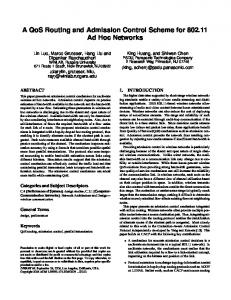
by two phases: i) ID-phase: consists in the IDentification of the available resource in an AD; this phase is used by potential users to select the service and by the network for resource brokerage purposes; ii) AC-phase: concerns the Admission Control of a new flow entering the AD and is dedicated to effect IDphase decisions. The result of the first phase consists in the construction of tables, as explained next, that characterize the service classes available in the AD. The overall reference architecture is reported in Fig. 1. The Wireless part of an AD (WAD) is constituted by Access Points (AP), Radio Nodes (RN), Access Network Routers (ANR) and the NRM. NRM
NRM
NRM
AP1
RN1
MAC domain of AP1
Administrative domain 1
ANR Administrative domain 2
RN2
AP2 AP3
Administrative domain 3 (WAD)
A class of service is characterized by two parameters: the Bit Error Rate (BER) associated to the class and achievable by a SNR target γT; the bit rate that can be sustained maintaining the given γT (named available bandwidth B(γT)). During the ID-phase the SNR tables are used in order to verify whether the rate R relevant to the service request can be accommodated in the WAD, given the requirement on the SNR. Once selected the service class, the AC-phase is based on the negotiated rate R and γT. The B(γT) for a RN depends on the geographical position of a RN in the system as well on the enabled transmission power and the interference at the RN receiver; different estimations of this quantity are obtained in downlink and uplink as well as for each RN. To reduce the complexity of the SNR tables it is possible to assemble only two of them (one for the down-link and one for the up-link) by averaging, for each class, the available bandwidth on the set of RNs present in the AP MAC domain. This corresponds to associate a characterization to a “generic” RN in the domain itself. III. RRC ALGORITHM
RN
Fig. 1 - General architecture An AP is a layer 2 entity evaluating the available resource during the ID-phase and controlling the access of the RNs during the AC-phase. Each radio entity (AP or RN) is in association with a MAC-domain area characterizing the covered transmission range. Different APs’ MAC domains can overlap (possibly just partially) and correspond to their coverage radio areas. The NRM has the task of guaranteeing the service negotiated by a flow and, to this end, interacts with the APs it is in control of. The ANR, as layer 3 entity, carries out functions mainly concerning the IP protocol. In general an ANR is in association with several APs and is the only entity of the radio access part interacting directly with the IP Backbone. In the philosophy of the Open Mobile Access Network foreseen in whyless.com, the access procedure is based on distributed operations involving both APs and RNs. Of course the local access decisions are not uncoordinated, on the contrary based on information concerning neighbouring links and obtained by signaling and measurements. A background broadcasting procedure is run by APs and RNs so that they can detect and acquire information about neighbouring radio entities. To this end a Broadcast-channel-AP(RN) is provided to by used by all the APs(RNs) to continuously transmit AP(RN) Broadcastpackets (B-packs) containing the AP(RN) identifier and information used for the RRC procedures. Thanks to the broadcasting procedure, the AP can derive the resource available in the domain and make service offers; these are collected by the NRM. A so-called SNR table stores the available bandwidth values for the M classes of service supported in a WAD, characterized by M different levels of SNR target.
We propose an interference-controlled RRC supporting QoS by making a link acquire a margin with respect to its minimum QoS requirements [6][8]. In particular an active link perceive an SNR level greater than the minimum required and thus can tolerate some extra interference; as a consequence, the accommodation of a new link does not necessarily require a transmission powers reconfiguration. In the following we indicate as MEI (Maximum Extra Interference) the additional interference sustainable by a receiver still maintaining the QoS negotiated for the relevant link. A link with MEI=0 cannot tolerate adjunctive interference without loosing the negotiated QoS. The admission control rule can be expressed as the problem of selecting, if exists, a suitable transmission power between i) the minimum required for achieving the desired link rate and the desired SNR; ii) the maximum to maintain, for the already active links, the negotiated rates and non negative MEIs. We contemplate an UWB system and the relevant expression of the SNR in hypothesis of gaussian approximation for the multi-user interference [12]. We consider the Impulse Radio (IR) modulation scheme where extremely short pulses (of duration 0.1-1.5 ns), named monocycles, are transmitted on a time axis structured in time frames (Tf), lasting typically hundred or thousand times the pulse duration, which in turn is divided in very short time periods (Tc). A bit is in association with Ns consecutive pulses and Pulse Position Modulation is used for the data communication. The multiple access is based on the adoption of pseudo-random Time Hopping (TH) codes whose elements are chosen among Nh possible Tcshifts within the period Tf. The use of the TH codes gives rise to a multichannel-multirate system that can be classified as “CDMA” oriented [12]. The SNR associated to the i-th link can be written as:
SNRi =
Pi g ii Ri [ηi + T f σ 2 I i ]
, Ii =
N
∑ Pj g ij
j =1, j ≠i
(1)
where N is the number of the active links. Pi is the average power emitted by the i-th link’s transmitter and gij the path gain from the j-th link’s transmitter to the i-th link’s receiver. Ri denotes the bit rate of the i-th link. The thermal noise power at the i-th link’s receiver is ηi. σ2 is an adimensional parameter depending on the pulse shape. The expression (1) is structurally similar to asynchronous CDMA. The main difference regards the value of key parameters like the mutual interference “weight” σ2. In addition, the UWB based on IR works efficiently even when different links in the network are asynchronous [12]; this makes it suitable for distributed wireless networking paradigms, as considered in the whyless.com project. The goal of the ID-phase is the construction of the SNR tables. We recall that a simplified procedure is considered here, referring to a generic RN by averaging on the parameters characterizing the set of RNs in the AP MAC domain. The AP collects, by listening to the RN B-pack, the following parameters indicative of the MAC domain status: the MEI level; the maximum transmission power the RN can emit; the two path gain values to and from the AP; the interfering power at the RN; the measured noise. The AP measures the perceived interference and noise and estimates its maximum transmission power Pmax on the basis of MEIs signaled in B-packs of other APs and RNs in the AP MAC domain. The path gain values are either calculated on the basis of the power used to transmit the Bpacks; this power level can be either fixed a priori (equal for all the B-packs) or signaled in the B-pack itself. The AP fills the SNR table by calculating, for the M values of γT, the available bandwidth in the down-link (Bdw(γT)) and in the uplink (Bup(γT)):
B dw / up ( γ Τ ) =
Pmax, AP / RN ⋅ g dw / up γ T [ηRN / AP + T f σ 2 I RN / AP ]
(2)
where the quantities gdw/up, Pmax,RN, ηRN and IRN, which would depend on the RN location, are calculated averaging on all the RNs in the AP MAC domain. The SNR table is refreshed periodically since the relevant parameters are highly influenced by the varying conditions of the MAC domain due to RNs’ mobility, channels variations, links activation/releasing. The maximum powers Pmax,AP and Pmax,RN takes also into account for the maximum power that a device can emit dev (named in the following Pmax ): it depends on both the device characteristic and on specific emission limits as that enforced by the FCC [13]. These values are computed as: MEI i dev Pmax,AP / RN = min Pmax , min (3) i g AP / RN i The AC in the WAD is performed in a distributed way and
has the task of checking if the rate and SNR requested by the user can be fulfilled. The level of interference MEIi that a link i (active at power Pi and with rate Ri) can tolerate before the SNR decreases till γiT can be found according to the expression:
g ii Pi = γ Ti Ri (ηi + σ T f I i + σ 2T f MEI i ) 2
(4)
The RRC algorithm evolves in the following way. 1) N-1 links are active at initial transmission powers such that they can tolerate positive MEI levels. 2) An N-th link (that has selected the desired service class on the basis of the SNR tables) attempts the access by calculating the minimum transmission power, Pmin,N allowing to reach the desired QoS and the maximum transmission power, Pmax,N not exceeding active links’ dev MEIs and the device maximum power Pmax . The access can take place if Pmin,N≤Pmax,N. 3) Within the range (Pmin,N, Pmax,N), if it exists, a transmission power level is selected which determines the acquired MEI level as well as the other links’ MEIs consumption amount. The parameters Pmin,N and Pmax,N can be calculated thanks to the cooperation between the new link’s transmitter and receiver. Pmin,N is computed by imposing that exactly the SNR target is achieved:
Pmin, N =
γ TN
R N η N + σ 2T f g NN
Pj g Nj j =1 N
∑
(5)
Pmin,N depends on interference level IN at the receiver and link extension, besides γT. Thus the link’s receiver must measure I and estimate the link extension by cooperation with the relevant transmitter. Pmax,N, calculated according to (3), is derived by neighboring links’ MEIs and their receivers’ distance from the link’s transmitter. As for the choice of the transmission power, while in [6] every new link enters the network acquiring a constant margin, we introduce a more flexible definition of the margin approach by providing an access with balanced MEIs. The optimal working point consists in the power Popt,N allowing to maximize the minimum margin which indeed constitutes a bottleneck for further accesses. In fact, from the point of view of a further entering link, the maximum access probability is reached when MEIs are balanced since an unbalanced condition would imply that at least one large MEI could be reduced in favor of links with less MEIs. This situation is shown in Fig. 2 where link number 3 tries to enter the system. If the new link enters at minimum power (Pmin,3) it acquires null MEI but reduces the impact on the other two active links. On the other side, if the link enters at the Pmax,3 it achieves a considerable MEI but reduces to zero the MEI of the link 1. As a consequence, the figure shows that Popt,3 is a tradeoff in acquiring a suitable MEI still preserving the other links. In general the actual possibility to enter the system
depends on RN location too. The optimal power Popt,N can be calculated by the new N-th link on the basis of MEIs and measured interference IN:
Popt , N
MEI + σ 2T I + η i f N N = min g 1≤i < N σ 2T f g iN + NN γ TN R N
(6)
MEI MEIold,1 MEIold,2
links with a given γT. More in detail the first link should select a power P1 depending on MEI0 by:
g11 P1 = γ1T MEI0 + η1
(7)
while MEI0 should be calculated as a function of N0 as:
g ex MEI0 /( N 0 g ex ) = γT η 0 + g ex P1
(8)
where gex is the expected path gain and MEI0/N0gex is the maximum power allowed to each new link. Of course the selection of power P1 will also consider, as in (3), the constraints on the maximum power of the device.
MEI3 MEI1 mini{MEIi}
IV. PERFORMANCE ANALYSIS
MEI2
0 Pmin,3
Popt,3
Pmax,3
P3
Fig. 2 - MEIs as functions of the new link’s transmission power
A. Signaling exchange to support the AC-phase and implementation issues The protocol supporting the AC algorithm is quite simple requiring the computation of few parameters, Pmin, Pmax, Popt, that can be obtained by signaling and measurements. A major component of the AC scheme is the broadcasting of MEIs which are updated by the receivers as their variations come about. We assume a periodic signaling of MEI levels by a field in the B-packs. Let us consider by two radio entities A and B willing to establish a link respectively as transmitter and receiver. A can be either an AP or a RN and vice versa for B. The protocol main steps are the following: 1) A contacts B in order to trigger in B interference measurements. The path gain can be estimated by comparing transmitted and received powers relevant to this message; moreover in the contact message A includes the desired SNR so that B can compute Pmin. 2) B notifies to A the minimum power Pmin. 3) In the meanwhile A collects MEIs signaled from neighboring receivers. The relevant messages either include the used transmitted powers or are transmitted at a a-priori known power level. Thus A can estimate the path gains between itself and the receivers. 4) A compares Pmin and Pmax: if Pmin≤Pmax the access can take place and the transmission power Popt is selected. 5) A acknowledges to B the eventual access success and notifies the adopted transmission power. B calculates its own MEI and signals to neighbors the relevant level. As transmission starts, the other links’ receiver will update their MEIs. The selection of MEI when no other links are active (say MEI0) must be specified. A criterion consists in setting MEI0 at the value that will allow the system, in further access requests, to accommodate a given number N0 of
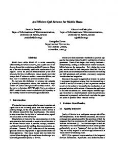
In this section we show some results corroborating the effectiveness of the proposed approach (here Balanced MEIs - B-MEI) with respect to the scheme proposed in [6] (here named Constant MEIs – C-MEI). As reference for the performance analysis, we consider also an ideal scheme reconfiguring powers to the Paretooptimal solution [3] giving rise to the minimum power consumption (in the following MINPOW). We assume this scheme behaves ideally rejecting links that would force some link’s drop due to maximum power saturation. We generated a number of topologies with N links, for different values of N, randomly located in a square area of 100m x 100m and estimated the probability of successfully activating all the links. The link rate is R=1 Mbit/s and the dev =0.5 mW, η=4 10-20 W/Hz. We target SNR γT=10. Pmax referred to a path loss decreasing as the power 2.4 of distance and equal to 1259 at 1 meter. The adopted signaling scheme is ideal: no collisions occur in the broadcast channels. Fig. 3 reports the probability of activating N links as a function of MEI0 for different values of N. Both for BMEI and C-MEI, initially the greater MEI0 the higher the probability of activating a number of links. Then the BMEI curves saturate due to the maximum power constraint limiting also the actually achievable MEIs. Instead, as for C-MEI, the curves first gain a peak and then decrease saturating to a certain level. In this case, since MEI0 represents the initial margin that each new link tries to achieve, the entering links generate higher interference that future links will have to overcome with higher transmission powers thus quickly saturating the maximum power constraint. Fig. 3 can also be interpreted as the access scheme behavior as a function of the MEI/power configuration indicating a possible criterion of reconfiguring powers in B-MEI. In fact, once identified the “elbow” of the curves, a reconfiguration process during communications lifetime could make the network move to the minimum level allowing to reach the saturation floor. In Fig. 4 the curve relevant to MINP sets the maximum probability achievable by any strategy. B-MEI outperforms C-MEI and further improvement is expected by introducing the reconfiguration mechanism which would make B-MEI curve closer to MINPOW. Both strategies B-
MEI and C-MEI require the signaling of MEIs. Instead, as for the distributed implementation of MINPOW, we remind that, although schemes based on probing the radio channel before and after the access has been proposed to implement such solution [10], the bound on the transmission power of a device is completely neglected while deeply affecting performance. 1
Probability of activating N links
N=5 N=10 0.8
B-MEI C-MEI
0.6
N=30 0.4
N=40 0.2
N=60 0 -12 10
10
-10
10
-8
10
-6
10
-4
MEI0 (Watt)
Fig. 3 - Probability of activating N links as a function of MEI0
Probability of activating N links
1
0.8
0.6
0.4 MEI0=10-8 Watt 0.2
0
B-MEI C-MEI MINPOW 0
5
10 15 20 25 30 35 40 45 50 55 60
Number N of links
Fig. 4 - Probability of activating N links as function of N V. CONCLUSIONS The paper deals with interference-controlled RRC in distributed wireless systems. The system at hand is based on UWB and aims at supporting QoS flows requiring a given SNR and bit rate. We propose an approach based on the maximum extra interference that can be tolerated by a QoS flow suitable to be applied in a distributed system where the optimal “minimum power approach” seems not applicable due to the high complexity required to reconfigure the transmission powers. With respect to the literature, our margin-based approach provides a MEI balancing procedure in order to reduce the link block probability typical of these incremental admission control approaches. In the paper we give the motivations that induce the adoption of the balanced margin approach and we show the performance results confirming these considerations. We also face implementation issues within the framework of the whyless.com architecture based on
the adoption of UWB and we show that the approach on the whole requires the exchange of few parameters by means of broadcast channels. Future work will be dedicated to design into details the UWB RRC protocol supporting the proposed strategy. REFERENCES [1] T.S. Rappaport; A. Annamalai, R.M. Buehrer and W.H. Tranter, “Wireless communications: past events and a future perspective”, IEEE Communications Magazine, vol. 40, no.5, May 2002, pp. 148-161. [2] N. Bambos, S. Kandukury, “Power-controlled multiple access schemes for next-generation wireless packet networks”, IEEE Wireless Communications, June 2002, pp. 58-64. [3] N. Bambos, S. C. Chen and G. J. Pottie, “Channel Access Algorithms with Active Link Protection for Wireless Communication Networks with Power Control”, IEEE/ACM Trans. On Networking, vol. 8, no. 5, October 2000, pp. 583-597. [4] F. Cuomo, A. Baiocchi, F. Capriotti and C. Martello, “Radio resource optimization in an UWB wireless access”, in Proc. of IST Mobile Communications Summit 2002, pp. 723-727. [5] D. Kim, “Rate-Regulated Power Control for Supporting Flexible Transmission in Future CDMA Mobile Networks”, IEEE JSAC, vol. 17, no. 5, 1999, pp. 968-977. [6] S. Lal and E. S. Sousa, “Distributed Resource Allocation for DS-CDMA-Based Multimedia ad hoc Wireless LAN’s”, IEEE JSAC, vol. 17, no. 5, 1999, pp. 947-967. [7] M. Xiao, N. B. Shroff and E. K. P. Chong, “Distributed Admission Control for Power-Controlled Cellular Wireless Systems”, IEEE/ACM Trans. on Networking, vol. 9, no. 6, 2001, pp. 790-800. [8] F. Cuomo, C. Martello, A. Baiocchi, F. Capriotti, “Radio resource sharing for ad-hoc networking with UWB”, IEEE JSAC, vol. 20, no. 9, pp. 1722-1732. [9] J. P. Monks, V. Bharghavan and W. W. Hwu, “A Power Controlled Multiple Access Protocol for Wireless Packet Networks”, in Proc. of INFOCOM 2001, pp. 219-228. [10] C. Zhu and M. S. Corson, “A Distributed Channel Probing Scheme for Wireless Networks”, IEEE INFOCOM 2001, pp. 403-411, 2001. [11] C. Martello, D. Bocchetta, “Power Controlled MAC Protocols for Wireless Ad-Hoc Networks”, in Proc. of European Wireless 2002, pp. 319-326. [12] M. Z. Win and R. A. Scholtz, “Ultra-Wide Bandwidth Time-Hopping Spread-Spectrum Impulse Radio for Wireless Multiple-Access Communication”, IEEE Trans. on Communications, vol. 48, no. 4, pp. 679-690. [13] Federal Communications Commission, Release 14 February 2002, http://www.fcc.gov.