A Packet Handling Scheme for QoS Support in an Integrated Satellite/Terrestrial System Paolo Dini1, Roberto Cusani1, Francesco Delli Priscoli2 University of Rome “La Sapienza” – INFOCOM1 Department / DIS2 Department Via Eudossiana 18, 00184 Roma, ITALIA Email:
[email protected];
[email protected];
[email protected] ABSTRACT – Since the Internet is today a sort of global multiservice network, a key consideration is support for services with guaranteed quality of service. The challenging objective of this paper is to propose a possible architecture to support Internet QoS-sensitive services (video-conferencing, voice over IP, web browsing,...), thus providing users with end-to-end QoS guarantees. A new hybrid Intserv/Diffserv scheme for handling IP packets by supporting QoS over an integrated, multi-segment network is here presented. It is implemented via a suitable QuAlity of service Support Module (QASM). The main advantages and drawbacks of QASM are discussed and the impact on both system architecture and Multi Mode Mobile Terminal is investigated. Performance evaluation, carried out via computer simulations, confirm the effectiveness of the proposed solution.
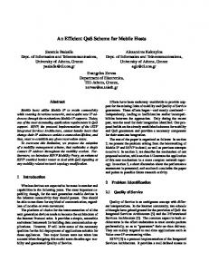
1. INTRODUCTION In order to have a global coverage to access the Internet services a satellite-terrestrial network has been studied and developed. The aim of this multi-segment network is to provide IP multimedia services with a guarantee end-toend QoS to mobile users. This system, called Global Mobile Broadband System (GMBS) consists of different mobile networks including GPRS (General Packet Radio Service), UMTS (Universal Mobile Telecommunication System), ESW (Euro Sky Way) and W-LAN (Wireless Local Area Network), all connected to an IP core network [1]. A reference scenario is shown in Figure 1. Each component of the GMBS has its own specific mechanisms to manage user QoS requests: the main challenge of such a system is to harmonize these different ways of operating so that the whole system can be seen, from a user perspective, as a single network providing global coverage and QoS guarantee multimedia services. A practical approach for such harmonisation, foresees that the modifications of both the access and core networks are kept at lowest level. A critical issue for GMBS is represented by the end-toend QoS provision. It is achieved via a QoS contract, on an end-to-end basis, which specifies all the basic features which must be guaranteed to the new connection once it is accepted. The problem of guaranteeing an adequate QoS to a certain connection can be conceptually divided into two parts: • Verify the availability of the requested resource over the whole path and accepting the connection, if it is possible, or negotiating a new contract. • Once the connection has been activated, continuously monitoring the effective QoS in order to guarantee that the stipulated contract is respected. A QoS contract includes the following fundamental definitions [2]:
Wired host NavigationSystem
FES
SAT
T- IWU
NIU
GPRS/UMTS QASM
HLR/ VLR
ESW SEGMENT
W-LINK
NOC NIU ER
ER
ER NIU
GMBS Mobile Terminal
Mobile User
ER EdgeSubnetwork ER
EdgeSubnetwork
FES
Internet Network ER
EdgeSubnetwork
ER ER
W-LAN GPRS/UMTS SEGMENT BS BS
2G BSS
ER R
CorePortion
EdgeSubnetwork ER ER
SGSN
GGSN HLR
3G URAN
FES: Fixed Earth Station ER:Edge Router
SGSN
Fig.1 - Reference scenario for the GMBS architecture
•
The “compliant traffic” is the traffic relevant to the connection (in the IntServ approach) or to the class of connections (in the DiffServ approach) which, in howany situation, has to be admitted into the network; the agreed QoS performance must be guaranteed for this kind of traffic. • The QoS performance of the compliant traffic is usually expressed in terms of maximum transfer delay, maximum loss and maximum delay jitter undergone by the Protocol Data Units (PDUs) relevant to the connection (or to the class of connections). • A rule for handling the “non-compliant traffic” must be defined; for example, to discard this kind of traffic, to downgrade its priority on the link, or to admit it into the network guaranteeing the QoS performance only if the network can afford it. The present paper aims at describing the QoS provision in the access network of GMBS. An IntServ approach has been adopted and the corresponding RSVP signaling protocol has been implemented [3], [4]. In order to provide users with the same QoS regardless of the access
segment supporting the communication a special module, the so-called QASM (Quality of Service Support Module) has been implemented. It is placed, on terminal side, between the underlying network layer (i.e. the radiotechnology dependent layers particular to the various Access Networks) and the IP layer, and, on network side, in the GGSN, for the GPRS/UMTS network, and in the FES, for the ESW network (see Figure 1). The main issue of QASM is to apply some actions to the IP flows (classification, scheduling, traffic shaping/policing...) which are generally absent in the network layers, in order to comply to the QoS subcontracts relevant to the wireless sub-network. QASM module is then a kind of universal adapter harmonizing the degree of QoS offered by the different GMBS wireless networks. 2. QoS SUPPORT MODULE
ARCHITECTURE
by the dashed blue lines, whereas the full black lines are related to the IP packets flow. It is worth noting that no QASM-specific header is added to the IP packets crossing the QASM. Comma nd
Command Description
C1
RSVP parameters exchange between RSVPIH and RSVPIE
C2
RSVP connection set up request response
C3
Segment Specific Connection Set up request and response
C4
QASM packet generation command
C5
Admitted connection registration/deregistr ation
C6
QASM configuration command
C7
QoSPT consultation
C8
Measurement Database consultation
C9
Congestion Control Measurement, Congestion Control execution Measurement Database updating
C10
C11
QASM functional entities are in charge of providing QoS support to the GMBS wireless sub-networks by providing traffic shaping and congestion control mechanisms, and their mutual interactions. A key feature of QASM is its transparency with respect to the interface between the IP layer and the upper layers of the underlying network. QASM processes IP packets without modifying the functionalities of IP and upper layers. The main reason to consider the QASM as a “special layer” (and not as a simple “module”) is due to its main functionality, i.e. to adapt a traditional cable network to a wireless one without being tailored to a specific segment. Regarding the QoS support provision, the QASM implements the following functions: • Interfacing the wireless access networks with the overall GMBS network from a QoS point of view: this means to be able to communicate with the RSVP Intermediate Entity (RSVPIE)1 during each RSVP connection set-up phase (i.e. contract definition stage) [5]. As a matter of fact, the GMBS system relies on the RSVP protocol, complemented by the GRIP protocol within the core portion of the Federated ISPs network, in order to ensure a certain end-to-end QoS provision, from the sender to the receiver, to the admitted connection [6]. This means that QASM must be inserted within a RSVP-aware node. • Performing traffic shaping and congestion control with respect to the currently active segment. • Monitoring the active segment congestion status in order to report the performed measurements to the CN-IWU. This functionality is performed only by the QASM at network side (N-QASM). Figure 2 describes the functional architecture of QASM special module and its signaling messages. The signaling among QASM functional entities is pointed out
1
This is the wireless segment RSVP entity participating to the end-toend RSVP signaling process. It is in charge of intercepting and reconstructing the RSVP messages in order to extract RSVP parameters, which are passed to the RSVPIE Handler [5].
Probing Packet generation command
Fig. 2: QASM functional model and internal signalling
As it can be notice by the figure above, QASM architecture can be basically divided into two major subblocks: the QoS Packets Processing Handler sub-block and the QoS Inter-working Handler sub-block. A description of these sub-block is detailed in the following. The functional entities belonging to the QoS Packets Processing Handler sub-block processes the IP packets crossing the QASM. It is composed by the Congestion Control Module, the Measurement Congestion Handler and the Scheduler Module. Its main tasks are: • Traffic Shaping, aiming to smooth down the traffic entering the QASM. • Traffic Policing, allowing the QASM to distinguish between compliant traffic and non compliant traffic. • Congestion Control, to avoid several congestionrelated problems. • QASM QoS classification: the QoS Switcher (i.e. a functional entity belonging to the Congestion Control Module) is in charge of assigning to each IP packet entering the QASM a specific QASM QoS class, depending on the relevant data flow. • Scheduling, performed by the Earliest Deadline First (EDF) Scheduler Module, to take into account the degree of priority of each IP packet, in order to meet the different delay constraints of multiple data flows. • QoS measurements management: the Congestion Measurement Handler is in charge of processing • a number of dynamic measurements related to the provision of congestion control. The above topics, which are fundamental for the proposed packet handling method, are detailed in Section III. The QoS Inter-working Handler sub-block comprises the Interceptor & Generator of QASM specific signaling, the RSVP Iterface Handler and the Connection Admission Control Handler. Its main tasks are:
•
• • •
•
QASM to QASM communication: the task is carried out by the Interceptor & Generator of QASM specific signaling, which is in charge of both intercepting and generating the QASM Signaling Datagrams (QSDs). RSVP Parameters/Segment Specific QoS parameters mapping, implemented by the Connection Admission Control Handler (CCH). Connection set-up/modification procedure activation; implemented by the CCH. RSVP Interfacing, implemented by the RSVP Interface Handler which manages the information exchange between the QASM and the RSVP Intermediate Entity RSVP Parameters/QASM QoS classes mapping, implemented by the RSVP Interface Handler which also performs the mapping of the RSVP QoS parameters into the four QASM QoS classes.
QASM functional model also comprises two databases: the QoS Parameter Table and the Measurement Database. are exploited by the QASM functional entities in order to retrieve useful static/dynamic information on both the QoS requirements of each active connection and the congestion status of the underlying networks. As a matter of fact, a key feature of the QASM is its capacity to perform QoS support by means of a proper traffic control strategy, which is based on a set of static inputs coming from the QoS Parameter Table, as well as on a feedback mechanism exploiting a set of dynamic inputs coming from the Measurement Database. 3. THE CONGESTION CONTROL MODULE QoS provision entails differentiated traffic management because of many possible different kinds of connections. As a matter of fact, every different application has its own “QoS contract” and every contract has its own QoS parameters such as bandwidth, end-toend delay, jitter, packet loss, which in general could vary with continuity. A basic issue, QASM architecture is based on, is the granularity with which different applications can be served by the network and the complexity of the algorithms necessary to provide the right QoS support. A suitable trade-off must be then found. In order to address and optimize such trade-off the QASM QoS classes are introduced in this paper. Every class, characterised by the presence of different traffic flows belonging to different applications, is processed using a different approach, according to the specific class QoS requirements. A main distinguishing factor between these applications is how sensitive the traffic is to delay (e.g. video conferencing applications are extremely sensitive to this parameter, whereas e-mail applications are totally delay insensitive). Moreover, a suitable correspondence between the QASM QoS classes and the underlying network QoS classes (e.g. UMTS, GPRS, ESW QoS classes) should be foreseen [7]. Four classes have been chosen as summarized in Table 1.
TABLE 1 QASM QoS CLASSES AND RELEVANT QoS CONSTRAINTS QASM QoS Classes
Type of Applications
QoS Constraints
1st Class
3st Class
Voice over IP,Video Conference Real-Time Audio-Video (MPEGs) Web Browsing, Telnet
4st Class
SMS, E-Mail, Ftp
Very Low Transfer Delay, Delay Jitter Low Transfer Delay, Delay Jitter Packet loss, Round-trip Delay Packet Loss
2st Class
When a new TCP/IP connection is admitted a new data flow crosses the QASM and the Congestion Control Module (CCM), together with the Scheduler Module, is in charge of providing the right QoS support. This module consists of several entities, as shown in Figure 3. IP traffic entering the CCM, is processed by the QoS Switcher, which is in charge of both selecting the QoS class and directing each packet to the appropriate part of the Congestion Control Executor. Then each packet is sent to the corresponding QoS queue. Finally, packets are processed by an Earliest Deadline First scheduler [8] that assignes the right priority according to their QASM QoS class and to the arrival time into the QoS queue. Traffic shaping and traffic policing functionalities are performing via the Dual Leacky Bucket (DLB) algorithm [9]. DLBs parameters are configured by taking into account RSVP Tspec parameters, stored in the QoS Parameters Table, and information about congestion status of the underlying networks, stored in the Measurement Database. In order to manage the four different QASM QoS classes, for both traffic shaping/policing and QoS queuing a hybrid IntServ/DiffServ approach is adopted by using Int-Serv and/or Diff-Serv for each QASM QoS class, as described in the following sub-sections. IP p ac k ets
Q o S S w itc h e r F o u rth c la s s (N 4) -------
T h ir d c la s s (N 3 ) ------ -
DLB
DLB
S e c o n d c la s s (N 2) ------ -----------
DLB
….
DLB
F ir s t c la s s (N 1 ) -----------------
DLB
..
DLB
C o n g e stio n C o n tro l E x ecu to r
Q oS Q u e u es
S c h e d u lin g M od u le (E D F ) IP p ac k ets
F irs t c hoice que ue S ec o nd c ho ic e qu eue
Fig. 3: Packet handling scheme inside QASM module
A. First QASM QoS class Packets belonging to this class have very strict delay jitter and transfer delay requirements. For these kind of application it is preferable to loose some packets than to increase the transfer delay. Fast packet processing is then required: this is obtained by processing first class packets in a completely IntServ manner, so that every connection has its own DLB and QoS queue. When a new first class connection is admitted, the RSVP Intermediate Entity Handler must make the QoS switcher create a DLB and a first class queue for the new accepted connection. The non-compliant traffic is
destroyed, because of the high requirements on transfer delay of this class. The benefit of reserving one queue for each first class flow, ensures a very low delay jitter. Queue length is, then, dimensioned only considering the maximum transfer delay allowed by the application.
• a standard GPRS terminal, with its protocol stack; it transmits video, voice, ftp, http and receives voice, http applications;
B. Second QASM QoS class All applications belonging to this class have more relaxed conditions on transfer delay than the QASM first class applications, but strict delay jitter requirements. An IntServ treatment is then assumed for the compliant traffic shaping/policing management. As the more relaxed transfer delay requirements, a second-choice queue is adopted for the non-compliant traffic. It can be processed by assigning a lower priority than the compliant second class packets. In order to reduce complexity (which increases proportionally to the number of connections also in QoS queue processing part) only one QoS queue for all second class connections is adopted. The second class packet are thus delayed but this unessential for this class. The second class QoS queue is dimensioned by considering the maximum delay jitter allowed by the application. The worst case occurs when the J-th packet belonging to a second class connection I enters the queue and finds the buffer empty and the (J+1)-th packet belonging to the same connection enters the queue when the buffer is full. In this case the relative delay between the two packets is proportional to the buffer length. The maximum relative delay between the two packets is given by the following formula: {queue length [packet size]}/{queue output bitrate} C. Third and fourth QASM QoS classes Third and four QASM QoS classes are less delay sensitive than first and second classes, but have more stringent requirements for the payload preservation. Third and fourth classes are then managed by a DiffServ treatment: only one DLB and one queue are reserved for each class and the non compliant traffic is sent to the second choice queue, one for each flow. In this way, the only difference in managing the two classes is the scheduling processing: for example, a third class QoS queue could have higher priority than a fourth class QoS queue. 4. SIMULATION RESULTS In order to evaluate QoS Support Module performance, several software simulations have been carried out using OPNET Modeler simulation tool. The main goal is to verify that inserting the QASM module into the protocol stack of the GMBS Multi-Mode Terminal does improve QoS handling by properly exploiting the lower layer resources. The simulated scenario basically consists in: • a GMBS Multi-Mode Terminal with its protocol stack, including the QASM; it transimits video, voice, ftp, http and receives voice, http applications;
Fig.4 Simulation scenario
• a GPRS access network to the Internet to receive http and ftp services; • a wired host receiving video and audio applications. A comparison between the main QoS parameters characterising each class has been performed for the GMBS and GPRS terminals by running two different kinds of simulations. The former concerns only the GPRS network QoS management (white lines in Figs.5-9) and the latter concerns the insertion of the QASM special layer into the GMBS terminal protocol stack (black lines in Figs.5-9). As it can be noticed analysing figs.5-7, the QASM “per-class management” does improve the QoS handling with respect to what offered by the sub-networks management layers only. In particular, delay jitter constraints are improved with an acceptable increase of the transfer delay for the real-time applications (i.e. first and second class). Another important feature of the QoS Support Module is its capacity to smooth traffic peaks. This characteristic is due to the presence of DLBs within the Congestion Control Module. For such operating mode, the QASM guarantees a better resource exploitation in terms of throughput and bandwidth allocation, as depicted in Fig.9. 5. CONCLUSIONS From the analysis of simulation results we can conclude that QASM architecture meets all the requirements it has been conceived for. QASM treats the IP packets in a transparent way, with no modifications. As a consequence, QASM special layer can be then inserted between IP and several networks DLC layers in a transparent way, granting an efficient QoS management and a traffic flow harmonization between the different networks. ACKNOWLEDGEMENTS The work concerning QASM architecture design has been performed and developed in the framework of the IST Project SUITED (multi-segment System for
broadband Ubiquitous access to InTErnet services and Demonstrator).
[1] P. Conforto, C. Tocci, G. Losquadro, F. Fedi, R.E. Sheriff, P.M.L. Chan, Y. Fun Hu, “Ubiquitous Internet in an integrated satellite-terrestrial environment”, IEE Comm. Magazine, January 2002, vol. 40, page(s). 98-107
0.6
delay (sec)
0.5 0.4 0.3 0.2 0.1 576
540
504
468
432
396
360
324
288
252
216
180
144
108
0
72
36
0 simula tion time (sec)
0.5 0.45 0.4 0.35 0.3 0.25 0.2 0.15 0.1 0.05 0
[4] R. Braden et al., “Resource reservation protocol (RSVP) – version 1 Functional specification”, RFC 2205, sept. 1997
576
540
504
468
432
396
360
324
288
252
216
180
144
108
0
72
[5] F. Delli Priscoli, G. Lombardi, F. Del Sorbo, D. Prisco, A. Fazio, “Integrated Services Mappings over a Multi-Segment Broadband Wireless Network”, Proc. IST Mobile Summit, Barcelona (Spain), September 2001. 36
delay (sec)
[2] R. Braden, D. Clark, S. Shenker, Integrated services in the internet architecture: An overview", IETF RFC 1633, July 1994 [3] J. Wroclawski, “The use of RSVP with IETF Integrated Services”, RFC 2210, September 1997
Fig.5 : First class end-to-end delay (voice source)
simulation time (sec)
Fig.6 : Second class end-to-end delay (video source)
[6] C. Tocci , P. Conforto, A. De Carolis, M. Femminella, F. Pugini, “Solutions and Techniques for the Provision of End-to-End IP QoS in a GMBS System”, Proc. IST Mobile Summit, Barcelona (Spain), September 2001. [7] 3rd Generation Partnership Project, Technical Specification Group Services and System Aspects, “QoS Concept and Architecture”, TS 23.107 Release 5, 3GPP Organizational Partners, 2002.
3 2.5 delay (sec)
REFERENCES
2 1.5 1 0.5 579
543
507
471
435
399
363
327
291
255
219
183
147
111
75
39
3
0 simulation time (sec)
Fig.7 : Third class end-to-end delay (web source)
7
delay (sec)
6 5 4 3 2 1 579
543
507
471
435
399
363
327
291
255
219
183
147
75
111
39
3
0 simulation time (sec)
Fig.8 : Fourth class end-to-end delay (ftp source)
300000 250000
150000 100000 50000
Fig.9 : Radio Interface Throughput
8
6
simulation time (sec)
58
54
4 50
2 46
0 42
6
4
2
8 37
33
29
25
0 21
6
8 16
12
84
42
0 0
bits
200000
[8] V. Sivaraman, F.M. Chiussi, M. Gerla, “End-to-end statistical delay service under GPS and EDF scheduling: a comparison study”, Proc. IEEE INFOCOM 2001, Vol. 2, pp.1113 –1122, 2001. [9] A.Elwalid and D. Mitra, “Traffic Shaping at a Network Node: Theory, Optimum Design, Admission control”, Proc. IEEE-INFOCOM 1997, Vol. 2, Kobe, Japan -.