Journal of Computer Sciences and Applications, 2017, Vol. 5, No. 1, 1-10 Available online at http://pubs.sciepub.com/jcsa/5/1/1 ©Science and Education Publishing DOI:10.12691/jcsa-5-1-1
An Introduction to Various Algorithms for Video Completion and Their Features: A Survey A. Ghanbari Talouki, M. Majdi, S. A. Edalatpanah* Department of Computer Engineering, Ayandegan Institute of higher education, Tonekabon, Mazandaran, Iran *Corresponding author:
[email protected]
Abstract Completion or inpainting is applied in order to reconstruct the hurted images and video frames. This
study proposes a survey on algorithms which complete corrupted objects (mainly humans) in video frames. Firstly, image inpainting is proposed as a mathematical problem and then it is extended into video completion problem. In the following, different types of video completion methods that are based on different types of video contents and the status of the background, foreground and camera movement is introduced. According to the method of the completion or the idea of considering the frame as one distinct object or considering it as a set of some fundamentals, there are several approaches to inpaint the video. Each video completion type is surveyed with the help of several studies about that.
Keywords: video inpainting, video completion, moving subjects, background subtraction, texture synthesis, similarity measure Cite This Article: A. Ghanbari Talouki, M. Majdi, and S. A. Edalatpanah, “An Introduction to Various
Algorithms for Video Completion and Their Features: A Survey.” Journal of Computer Sciences and Applications, vol. 5, no. 1 (2017): 1-10. doi: 10.12691/jcsa-5-1-1.
1. Introduction Video inpainting or video completion is known as one of the appealing subjects in video processing. The goal in video completion is to restore the lesion parts of the video named holes; holes are made by elimination of an occluding object. Achieving this, a similarity measure is gained to find the most appropriate data which is used for filling in holes. It should be considered that inpainting is done so that it will not bring forward pixels that may make the result unpleasant to the viewer; it is important to retain the visual achievement of the completed video [1]. An initial study for extending image inpainting algorithms to video inpainting ones consider the video data as some distinct images [2]. Therefore, there are some exclusive images that image inpainting procedures can be executed separately to each of them. Hence, the high temporal consistency between the frames of the video is not brought up in this method and as a result, outcome would not be pleasant [3]. The hole which is supposed to be inpainted is made because of two reasons: 1) The objects of the video may conceal the other objects of the proposed video. 2) The objects of the video may be concealed by the other objects of the proposed video. In both cases, removing the unwanted object will lead to a hole that is supposed to be amendment [4]. Human’s eye is more sensitive to motion rather than lighting changing. As a result, temporal consistency is more important rather than spatial consistency in video completion; In other words, if the inpainting method is
applied to a video of moving objects, the restored portions will be unrecognizable in the result video and the more important is that the continuity of motion should be preserved for the moving object. As described above, the researchers aim to introduce methods which complete the hole without disturbing the motion consistency of the moving object [5]. In this paper, we firstly introduce the image inpainting as a mathematically problem. Then, different inpainting problems will be expressed. Finally, a survey on previous studies about video completion will be proposed.
2. Image Inpainting as a Mathematically Problem As mentioned before, the point in image inpainting is to define color values for hole pixels of the original image. Since visual consistency is the evaluation criterion, the completion must be done so that generates the least inconsistency with the other pixels [6]. To do this, the structure as the texture will be consistent in both the restored portion and the rest portions [7]. To define an image, the set P is introduced as a set of points, either given ones or not given ones. If we suppose the image’s dimensions as w × h (w is the width and h is the height), then the set P for the image is defined as Eq. 1: = P
{[ x, y]
T
}
| x, y ∈ N ,1 ≤ x ≤ w,1 ≤ y ≤ h
(1)
p = [x,y] T is used to define each pixel of this image. Therefore, the image I is defined as a function
Journal of Computer Sciences and Applications
2
I : P → [0, 255]d ⊂ Z d . d=1 for grayscale images and d=3 for the color images(any color space). P is the pixel, I(p) is the light intensity for grayscale images or color for color images. The video is consisted of several frames that each frame is actually an image. Suppose that there is a video of f frames, each of them is w × h . The point set of this video is shown as Eq. 2: = P
{[ x, y, t ]
T
}
| x, y, t ∈ N ,1 ≤ x ≤ w,1 ≤ y ≤ h,1 ≤ t ≤ f . (2)
Each pixel in the video is described as p = [x,y,t]T . The fourth dimension that is the light intensity for gray video or the color p for color video will be defined as before. You can consider the completion algorithm as a function. The components of this function are an image and a set of points that must be completed (set of points which are located in the hole). The output of this function is an image with dimensions equal to the input image and the information that is placed instead of the hole. The other name for hole is the "target area" and we will display it with Ω ∁ P. Completing the picture gradually makes the target area smaller and smaller so that no pixel belongs to this part of the area. The completion function is mathematically shown as Eq. 3:
= I ' C ( I , Ω).
(3)
Border of Ω is the point set of Ω that at least one of the neighboring pixels of that is not a member of Ω. This collection points are displayed as Ωδ. To complete the image, we use a mask. This mask is a binary image that is defined as Eq. 4:
0 M ( p) = 1
p∈Ω . p ∈ P − Ω
(4)
To complete the image, we use the information of the non-damaged parts of that image. This area that has the right information is named as the reference area or the source region. This area is displayed mathematically as Eq. 5:
ϕ= P − Ω0 .
(5)
In Eq. 5, Ω0 is used to display the damaged area at the
beginning of the algorithm. As described earlier, the hole changes when the algorithm runs. Consequently, to distinguish between the hole at the first step and the hole at the current step, Ω0 is applied for the hole at the first step and Ωt for the hole at the current step. But when it is clear, Ω is applied for both of them.
3. Video Completion Solutions Different video completion solutions are introduced in subsection 3-1. In subsection 3-2, an overview of the past strategies on video completion will be proposed.
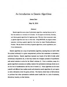
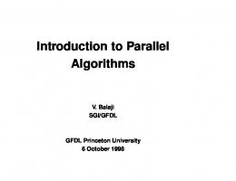
3.1. Types of Video Completion Problems Video completion problem can be divided into three groups [8]: A) stationary backgrounds with moving objects B) non-stationary background with stationary objects C) non- stationary backgrounds with moving objects The most available videos are as (a). As a result, we primarily introduce all these three groups briefly and then we extend only (a). For case (a) we can develop the image inpainting algorithms and use them. The main emphasis is on the recovery of the background that needs to be done appropriately. As explained in the previous section, image I ′ C ( I , Ω) . It inpainting procedure operates as function= means that having the input image and the hole, the output image(i.e. the restored image) will be produced. Figure 1 is an example of the video of case (a). In the case of (b) we have a fixed object. A fixed object means that the location of the object relative to the background does not change but the background moves. To read more about the researches in this field you can see [8]. Case (c) is the most sophisticated video completion problem that in which, both the background and the foreground move [9]. It is because of the various movements of the camera. In theory, the continuity of the damaged background or the damaged moving object that is occluded by another object will be maintained after restoration [10]. An example of time continuity can be displayed by a moving map as in Figure 2.
Figure 1. An example of the video with stationary background and moving objects [8]
Journal of Computer Sciences and Applications
3
Figure 2. is an example of a non-stationary background video and moving objects [8] (a) a frame of video (b) moving map of this frame
In Figure (2-b) arrows show that the background move downward. White area indicates that the object is stationary. Most of the videos that have been used by other researchers are in group (a). Also, there are some researches that consider (b) and (c) categories [11]. Therefore, from now on, we will only consider the type (a) of videos.
of video. Then u and v are obtained from the Eq. (9) and (10) respectively.
3.2. Review of Previous Video Completion Solutions
If there only is horizontal movement, Eq. (9) shows the moment movement in x-direction and if there is only vertical movement, Eq. (10) shows the moment movement in the y-direction. As dedicated in Eq. (8), [13] applies the sum of squared difference (SSD) to compare two patches to find the most suitable patch. According to the method presented in [13], for a special point p in H (holes), several patches can be found that involves point (p). These patches are called wp1 to wpn. Also assume that the most appropriate patches for wp1 to wpn are wq1 to wqn, respectively. Since all space-time patches involving the point p must have the same color value in point p, the Eq. (11) is used to find color components for a specific point p.
The methods used to complete the video can be categorized into five groups [12]: 3.2.1. An Algorithm Based on Texture Synthesis Ref. [13] applies texture synthesis based method to complete the holes. For more explanation about this method, we first define the concept of visual compatibility. The sequence S has visual compatibility with the sequence T if any space- time patch s could be found somewhere in the sequence T. By this definition we assume the hole H is in the sequence S. The aim is filling in H by some new data H * so that the new obtained sequence S* is the most visually compatible with the sequence T; T is a database for completing the hole. In general, T = S \ H, the remaining parts of the video that are out of the hole. The completed sequence S* must satisfy the condition below:
coherence( s* | T ) = ∑ p∈S * max k ( w p , wq ).
(6)
q∈T
In Eq. 6, p and q act as all space-time points of their own sequences. WP and week are space-time patches with the centroid of p and q respectively. Here k is the similarity measure that is defined as Eq. 7. k ( w p , wq ) = e
= d ( w p , wq )
∑
( x, y ,t )
− d ( w p , wq ) 2×σ 2
w p ( x, y, t ) − wq ( x, y, t ) .
(7) (8)
For each point (x, y, t) in patches wp and wq, wp (x, y, t) and wq (x, y, t) is a five-dimensional vector (R, G, B, u, v). (R, G, B) are color components. To obtain u and v, the spatial and temporal derivatives are firstly obtained as (Yx, Yy, Yt); Y represents a sequence
u=
Yt Yx
(9)
Y v= t . Yy
(10)
∑ si ci
c= i
∑ si
.
(11)
i
In the above equation si = s ( w pi , wqi ) and ci is the obtained color components for each of the patches wp1 to wpn. Eq. (11) minimizes the variances of the color components obtained for point p and thus the most likely color component (c) for each point p is achieved. Figure 3 depicts that how the two patches involve the point p. Given the size of wp, this overlapping can be done by more than two patches. In this method, the hole region is manually selected in all frames. To determine the color components of a special pixel, several patches are applied. Thus, time consuming of this approach is considerable. Disadvantages of the results of [13] cause the writers of that paper expand their research to [14] and apply multi – resolution pyramids in order to gain more compatibility and less running time. This procedure is a recursive procedure and at any step, the input image resolution is halved. That is, in both time and space, the next image is half the size of the previous picture. Figure 4 shows the multi-resolution pyramid.
4
Journal of Computer Sciences and Applications
As depicted in Figure 4, hole completion starts at the lowest level and ends at the highest level that is the same size as the input image. This approach somewhat improves the visual quality of the video. Ref. [15] uses texture synthesis to fill in the video. Also, the background and the foreground are firstly separated. Dividing the video into two sections, the background and the foreground lead to improve the visual quality of the completed video. Figure 5 shows an example of the process of completing a hole in accordance with the procedure provided for in [16]. This approach applied the algorithm presented in [17], which later improved on [18].
Figure 3. Two patches overlap at one point [13]
Figure 4. Using multi-resolution pyramid to complete the video [14]
Figure 5. the process of hole completion in [16]. a) The main frame b) The green dots are the highest priority for completion. c) The red square specifies the patch that must be filled in. d) the most appropriate frame for completion e) the specified patch has been copied. The red region indicates the priority of zero. f) Stop copying patches
Journal of Computer Sciences and Applications
Ref. [19] completed the video using a two-pronged approach such as [16]. The difference between these two methods is about the foreground completion. Ref. [19] at the beginning restores the first damaged frame using [17] and [18]. The hole in the first damaged frame is defined as
Ω0 . For the next holes (Ω 2toΩt ) , it acts in this way: the overlapping region of the current frame and the previous frame is determined and this area is copied in the current frame. If the occluding area of two frames is called µ t ,
Ωt \ µ t should be restored instead of Ωt in each step. Here time continuity is not considered. Ref. [20] has added the concept of stick figure into the previous researches. Figure 6 shows the foreground and its stick figure. It is noteworthy that this study segments the video into two parts; the foreground and the background. The authors of this study claim that using of stick figures cause body parts such as head, hands and feet be separable. As a result, the patches of each part can be copied separately into the hole, but this study give no more information about the separation method and detecting the patch of each portion. Although, they believe that there is no way to complete the hole when the whole object is removed. One more thing is that the restoration which is done may be visually satisfier but conceptually it may have wrong data into the hole. Fast movement of the moving object as well as large holes is the problem of most of the video completion methods. Another study conducted for using in texture synthesis is proposed in [21]. The proposed method is also facing the same problem. In addition, the method does not consider the camera movement. The use of morphological components in removing the subtitles of the video has been studied very much. Ref. [22] tried to apply this idea in order to eliminate the moving objects in video. But with the increasing number of the input frames, the scene becomes blur in the reconstructed video.
5
Researchers believe that video completion differs from applying image completion into each frame. Though, a new study on image and video completion [23] has used this method; it firstly applied undamaged frames to model the texture. Then this generated model is used to restore the damaged textures. As we have said earlier, maintaining the visual quality of the video is very important to compare the results of the completed video. In order to preserve the visual quality of the video, the continuity of the moving object must be preserved. For this purpose, [24] has developed the procedures in this field, so that the patches are three times larger than the size of the object in the foreground. Therefore more than one frame in each step of running of this algorithm is completed. Figure 7 shows one level of running of the algorithm. The bounding box for the foreground objects has different size in different frames. As a result, the size that is three times larger than the size of the box, may does not involve three foreground objects, as shown in Figure 7. Therefore, the occluding object must be removed. Repetition of this procedure will repair damaged frames. Ref. [24] as well as earlier researches inpainted damaged videos by considering periodic moves. Taking larger patches lead to more continuity in movement. Yet, however there are some jumps entering in and exiting from the hole.
Figure 6. Moving object and stick figure [20] a) foreground b) stick figure
Figure 7. One level of implementation of the algorithm proposed in [24]
Journal of Computer Sciences and Applications
6
Figure 8. frame types for damaged video [25]
3.2.2. Object-based Algorithms One of the first attempts that has been done in this area is proposed in [2]. This study consider partial occluding objects same as total occluding objects; the undamaged part of the Figure 8 is not considered. Figure 7 shows a frame of the video. Moving object in this figure is partially damaged in some frames. But in [2] the object is considered to be completely damaged. Here the foreground and background are separated firstly and then each of the two parts are completed separately. To complete the foreground, a similarity measure is used in order to find the best foreground in the database. This similarity measure is defined according to Eq. 12.
+ +
1 i ∑ d (oi , Ot j +i − j ) i < w−1 i + 1 j = 0 1
min
t0 ,...,th + w− 1
∑
h + w− 2 1 ∑ d (oi , Ot j +i − j ) i > h + w− 2 2h − i + 1 j =i − w+1
∑
h + w− 2
∑
i =w−1
1 w
i
∑
j =− i w+1
(12)
d (O
w , Ot j +i − j ). t w + i− 2 2
In Eq. 12, Oi is the object before and after the hole.
Oti is the object stored in the database that will be used to complete the hole. H is the number of holes that must be completed and w is the size of the window of the object template. D indicates the differentiates of the sum of the squares.
t0* ,..., th*+ w−1 are the optimal candidate objects for completion. The first two terms in Eq. 12 calculates the cost of compliance between candidate objects and real objects before and after the hole. The last term in Eq. 12 depicts the cost between consecutive windows of candidate objects inside the hole. 1 1 1 and are used to normalize , Weights i + 1 2h − i + 1 w the contribution of each frame. The candidate object o w is used to interpolate frame i. The authors of t w + i− 2 2
this article have developed their researches by considering partially damaged objects [25]. To consider these objects, the similarity measure changed as Eq. 13. d (oi , Oti ) ≅ min E0 (oi , Oti , m) + E N (oi , Oti , m) m
E0 (oi , Oti , m) ≅
∑
p∈M i
[oi ( p ) − Oti ( p + m)]2 M i ( p ) M ti ( p + m) (14)
E N (oi , Oti , m) ≅ ( 255 )
2
∑
p∈M i
M i ( p )[1 − M ti ( p + m)].
(15)
In Eq. 14 and 15, M i and M ti are binary masks that show objects oi and Oti , respectively. The vector m
t0* ,..., th*+ w−1 = arg
Eo and EN in Eq. 13 are similarity measures in occluding and not occluding regions respectively and are gained from Eq. 14 and 15.
(13)
illustrates the measure of shift of Oti in calculation SSD. Figure 9 depicts the situation that the moving object has nonparallel motion relative to the image plane. As a result, the scale of the object differs along the video. Thus, objects in database have various scales. Considering the fact that filling in the hole is done with the help of the objects of the database, the scale of these objects must vary and get the same size. Ref. [26] uses Eq. 16 to 19 to do this. L= _ MBR 'j L _ MBR j × γ x
(16)
W= _ MBR 'j W _ MBR j × γ y
(17)
γx = γy =
L _ MBR j
(18)
L _ MBRi
W _ MBR j W _ MBRi
.
(19)
In above equations γ x and γ y are scale operators for length and width of the image. MBR is the minimum boundary rectangle for the object. If the motion of the moving object is parallel relative to the image scene, the moving object has different scales of MBR for various situations of movement. Therefore, the maximum size of MBR is considered as the scale of the object's bounding box. MBRi and MBRj are the length of MBR for objects i and j, respectively. W_MBRi and W_MBRj are the width of MBR for objects i and j, respectively. Ref. [27] is another study which applies object instead of patch to complete the video. Object-based methods take less time to complete a hole subjects [28].
Journal of Computer Sciences and Applications
7
Figure 9. Non-parallel motion of a moving object relative to the image plane [29] a) the object's place in different frames b) database obtained from the moving object
3.2.3. Algorithms Based on Motion Vector Ref. [29] has used three steps for hole completion: A) A video sequence is divided into different motion layers. Accordingly, the order of the layers in overlapping areas can be determined. B) Here, removing the object means removing one layer. Holes made from removing the object will be filled by motion compensation and region completion. C) The completed layers for each frame get together in order to have the resulted video. Now, a brief description of each of these sectors will be proposed: A) separation of motion layers: At this stage, the number of motion layers is determined and the layers will be separated from each other. B) layer compensation and completion: Motion layer obtained from the previous step is only consisted of either background or a distinct object. So removing the object can be easily done by removing the object's layer. Let us assume the removed layer is i. In this case, after removing this layer, all the layers with a smaller number may involve holes in some frames. A motion template is used for each uncompleted layer with the purpose of finding motion parameters between frames. Then, a compensatory frame is generated in each layer. In order to produce this frame, other frames and the corresponding motion parameters are used. In most cases after this, it can be seen that large portions of a layer have missed its color and texture information. To fill these areas, [29] applied graph-cut based picture completion. For more information about graph-based method [30] refer. C) frame composition: All information about texture and color for each synthesized layer of a specified frame is available after the second step. Now these layers must be combined to
generate the completed frame; Motion parameters of layer is used for this purpose. This makes time continuity to be maintained for all video frames. 3.2.4. Algorithms Based on Partial Differential Equations (PDE) Research conducted in [31] has used PDE to reconstruct the damaged images. Holes which were considered here were small holes. Smallness caused the generated dissociation from completion algorithm not be seen so much. Therefore, [32] has developed the algorithm introduced in that study so that the higher-order PDE could be used. Before this study each frame of a video was considered as a distinct image and video completion has been done as some image completion. Yet, [32] distinguished between image completion and video completion for the first time. Damages that in each of these two studies [31] and [32] were intended has been in the form of lines. According to the algorithm presented in [32], the user must manually specify hole region. Filling in the hole is done somehow the hole (Holes here are lines with a specified thickness) is completing from outer to the inner portions; it means that completion is done from correct regions into the damaged regions. Different structures do not make problem for the results of the implementation of the algorithm. This algorithm completes the hole with the help of a mathematical function that is proved to be correct. Of course, it should be mentioned that parameter definition is done manually. Texture is not considered in this algorithm. 3.2.5. Hybrid Algorithms Ref. [33] has used a combination of methods based on motion vector and texture synthesis. Firstly, as shown in Figure 10 the motion vector is acquired.
Journal of Computer Sciences and Applications
8
patch. p is the center of each patch. Having target patch (pt) and its location (xt), the reference patch can be found with the help of the suitable xs achieved from Eq. 23.
p s ( xs ) = arg min d ( ps ( xs ), pt ( xt )) p s ( xs )
When the most suitable patch from reference region p s has been found, this patch can be directly copied into the hole; so that some parts of the hole is completed. The question in hole completion is how to select the next patch for completion. The procedure introduced in [18] has addressed this question. This procedure prioritize pixels, then that pixel which has a higher priority is chosen as the target patch center for next completion.
Figure 10. Acquiring motion vector from [33]
As illustrated in Figure 10, frames are divided into rectangular blocks. Then the blocks are searched in the previous and next frames. In Figure 10 the beginning and end of each arrow represents the source frames and frames that were searched. Each block of the frame need three independent searches in order to find motion vectors. The first search is from the frame n into the frame (n-1). The second search is from the frame n into the frame (n+1) and the third search is from the frame (n+1) into the frame (n-1). Thus, as shown in Figure 10, motion vectors in the previous and next frames are specified. This study combined the obtained motion vector by the procedure introduced in [18]. The main disadvantage of procedure [18] is that it searches the frame with the purpose of finding the most suitable patch. But the motion vector limits the search area. Another research that combined two methods, methods based on motion layer and the ones based on texture synthesis is [34]. This study uses known motion vectors to predict the motion vectors in the hole. Therefore, it specifically provides good results for periodic motions. To start with, the motion vectors in video except for areas designated as holes are determined. Eq. 20 is used for this aim.
δI δI δI arg min ∑ (u +v + ) δx δ y δt (u ,v )
(20)
δI δI δI , and are image derivatives δx δy δt according to spatial and temporal axis. Motion vector T (u , v ) minimizes Eq. 20. The estimated motion vector for In Eq. 20,
point p = ( x, y, t )T in the video sequence is shown as
(u ( p ), v( p ))T . In order to compare motion vectors and find the most similar motion vector, a similarity measure is defined. Eq. 21 and 22 are used for this purpose. m .m d m ( m0 − m1 ) = 1− 0 1 = 1 − cos θ . m0 m1
(21)
In Eq. 21, θ is the angle between two vectors m0 and m1 . d ( Ps ( xs ), P= t ( xt ))
1 D
(23)
∑ dm (m( p + xs ), m( p + xt )). (22)
p∈D
In Eq. 22, | D | is the number of defined pixels. xs and xt define the location of the source patch and the reference
3.3. Time Continuity in Video Completion The most significant point that differs image completion from video completion is time continuity for object motion that must be preserved in video sequences. Thus if image inpainting algorithms be only used for video inpainting, it will reduce the visual quality of the completed video. Therefore, these methods must be changed so that they could be applied. If we look at the recent researches on video completion, it can be found out that the recent methods tend to two-step procedures [35]: • Segmenting the video into two zones: foreground and background • Completion each of individual region: foreground and background complement According to the above description the video completion algorithms are generally divided into two groups: • Algorithms that use one-step procedures • Algorithms that use two-step procedures. 3.3.1. One-stage Video Completion Algorithms These algorithms consider each frame as an input and fill in the hole with the help of a completion algorithm. These completion algorithms can be performed as each of the five methods described above. An example of the algorithm has been proposed such that is [36]. Algorithms that follow the idea of two–step completion will offer better results because of two reasons [37]: firstly, dividing the video into various layers not only produce better results for adaption but the search space needed to find appropriate patches for completion will be reduced. Secondly, using a suitable image completion method, the background can be completed faster. 3.3.2. Two-step Video Completion Algorithms These algorithms divide the video into two parts; foreground and background. Then each of these sections are completed separately. An example of this method is [24]. Separation of foreground and background leads to definition of other issues: separating moving objects from the background and tracking the moving objects. Separating moving objects from the background: to do this, a model of background can be achieved. Then, the differences between each frame and the background is obtained. If there is a significant change between some area of the image and the background model, it means that a moving object exists here. Ref. [38] modeled the color
Journal of Computer Sciences and Applications
of each pixel of the static background with the help of a Gaussian distribution model in color space YUV to obtain a gradual change in time.
I ( x, y ) ≈ N ( µ ( x, y ), ∑ ( x, y )).
(24)
The parameters of the model, mean µ ( x, y ) and covariance
∑ ( x, y) are obtained considering the color in
several successive frames. After the background model has been obtained, for each pixel (x, y) of input frame the probability of its color is calculated using Eq. 24. Pixels that differ from the background model and this difference is more than a threshold are marked as foreground pixels. Using only a Gaussian distribution to model the background for open-door spaces is not correct because there may be several colors in a special place and this variety in color is because of shadow and reflection of moving object [39]. So, to solve this problem [40] used a combination of several Gaussian distributions to model the color of the pixel. In this method the pixel in the current frame is compared to each of the Gaussian functions in the background model in order to find its corresponding Gaussian distribution. If the corresponding Gaussian distribution was found then the mean and variance of the distribution will be updated. But on the other hand if no corresponding Gaussian distribution was found, then a new Gaussian distribution with mean equal to the current pixel's color and predefined variance is added into a combination of Gaussian distributions. Finally, according to whether the distribution belongs to the background or foreground, all pixels are marked. There is another way to do this; it uses data in the area of the image instead of pixels. In this method a pixel is not only matched with another pixel but is matched with a neighborhood of that pixel, too. One of the researches in this field is [41]. This approach considers small background movement or camera shakes. Changing the lighting will not change textures so much. Therefore, some researches such as [42] were used to separate foreground and background using textures. Ref. [43] did this separation using a combined approach. It means that in addition to pixels, region and frame are also considered. Pixel is used to predict the color of the background. Using the region, foreground regions that are same colored are identified. Talking about frame, if the most pixels change together, it means that the background model acquired from pixels-based method is wrong. Thus another model is considered for the background. Some studies also looked at the shadow [40]. Methods which ever have reviewed, separating the foreground and background, all have a common limitation; All these methods consider the static background. Some researches have offered methods to fix this problem. For more information about these methods you can see [44]. Moving objects tracking: The goal is to determine the position of the object in each frame of the video. According to which model is used for object presentation, motions and shape changing that an object could have, will differ. According to the concept that, these methods detect one object or more than one object, they are divided into two groups: Tracking one object: In some studies the template is used. These methods assume that an object template such as Ot from the
9
previous frame is specified. Then they look at the current frame to find a region of the image that is similar to Ot. Patterns are usually specified by characteristics such as color or brightness [45]. Since the brightness of the image is very sensitive to changes in lighting, [46] has added the gradient to the set of the image features that are used to search for a suitable template. High computational cost of methods that search for a suitable template is these methods’ disadvantage. Therefore, by limiting the search space to the neighborhood of the search space in the previous frame, computational cost can be reduced [46]. For more information about a more appropriate algorithm you can study [47]. The color histogram can be used instead of pattern to track an object. The average color of the pixels of the object to which the object is limited to a rectangle or ellipse is calculated. Ref. [48] just consider eight neighborhood directions in order to reduce the computational cost. The ratio of the average color of the intended object and candidate places is calculated. The place which has the most value for ratio is considered as the object's place at the current frame. Other researches tried to use the histogram by making changes in [48] but they offered solutions to make better use of the histogram. For more information about these researches you can see [49]. Tracking several objects: Ref. [50] converts the image into a set of layers; so that one layer belongs to the background and each object belongs to a layer. Depending on the characteristics of the shape and the motion of the object in the previous frame, the probability of belonging of each pixel to different layers is calculated.
4. Conclusion In this study, we firstly got familiar with the concept of image completion and learned how to generalize it into video completion. Then image completion has been introduced as a math problem and the concept of visual quality from a mathematical point of view has been proposed. We also have expressed different ways of video completion that include stationary backgrounds with moving objects, non-stationary background with stationary objects and non- stationary backgrounds with moving objects. We introduced various aspects of video completion algorithms that are based on texture synthesis, object, motion vector, partial differential equations and hybrid algorithms and provided an overview of the algorithms used for video completion. The advantages and disadvantages of each of these algorithms were scrutinized. We also have talked about both one-step and two step video inpainting algorithms.
References [1]
[2]
Satpute S.B., Gadge S.D., Kadnar G.T, “Super Resoloution-based Image with Video Inpainting”, International Journal of Engineering Science & Research Technology, 4(10), 202-205, 2015. S. S. Cheung, J. Zhao,M. V. Venkatesh, “Efficient Object-Based Video Inpainting”, IEEE Int. Conf. Image Processing, pp. 705-708, 2006.
10 [3] [4]
[5] [6] [7] [8]
[9] [10]
[11] [12] [13] [14] [15] [16] [17] [18] [19] [20] [21] [22] [23] [24] [25] [26]
Journal of Computer Sciences and Applications Tejasvee B. P., Dhar R., Rajasvee P. P., Jawalkar P.B., “Video Inpainting Using Image Inpainting”, International Journal of Computer Science and Mobile Computing, 4(10), 105-110, 2015. A. J. Pawar, A. P. Phatale, “A comparative study of effective way to modify moving object in video: Using different inpainting methods”, 10th International Conference on Intelligent Systems and Control, 1-5, 2016. P. N. Nya, C. Stuber, T. Wiegand, “Texture Synthesis Method for Generic Video Sequences”, IEEE Int. Conf. Image Processing, 3, 397-400, 2007. Tejasvee B. P., Dhar R., Rajasvee P. P., Jawalkar P.B., “Video Inpainting Using Image Inpainting”, International Journal of Computer Science and Mobile Computing, 4(10), 105-110, 2015. C. Ballester, M. Bertalmio, V. Caselles, G. Sapiro, J. Verdera, “Filling-in by Joint Interpolation of Vector Fields and Gray Levels”, IEEE Tran. Image Processing, 10, 1200-1211, 2001. T. K. Shih, N. C. Tang, J. N. Hwang, “Exemplar-Based Video Inpainting Without Ghost Shadow Artifacts by Maintaining Temporal Continuity”, In Proc. IEEE Trans. Circuits and Systems for Video, 13(3), 347-360, 2009. M. Soryani, A. Ghanbari, A. Koochari, “Dynamic Video Texture Inpainting Using Improving LDS”, British Journal of Mathematics & Computer Science, 4(20), 2872-2883, 2014. M. Granados, J. Tompkin, K. Kim, O. Grau, J. Kautz, C. Theobalt, “How Not to Be Seen — Object Removal from Videos of Crowded Scenes” , In Computer Graphics Forum, 31(2), 219-228, 2012. Newson A., Almansa A., Fradet M., Gousseau Y., Pérez P., “Video Inpainting of Complex Scenes”, SIAM Journal on Imaging Sciences, 7(4), 1993-2019, 2014 Vinod R. T. , Nitiket N. M., “An Intelligent Video Repairing Approach Using Object Inpainting: A Review”, Internation Journal Of Research in Advent Technology, 4(3), 236-240, 2016 Y. Wexler, E. Shechtman, M. Irani, “Space-Time Video Completion”, In Proc. IEEE Conf. Computer Vision and Pattern Recognition(CVPR), 1, 120-127, 2004. Y. Wexler, E. Shechtman, M. Irani, “Space-Time Completion of Video”, IEEE Trans. Pattern Analysis Machine Intelligence, 29(3), 463-476, 2007. Wang. M. , Yan B. , Ngan K. N., “An efficient framework for image/video inpainting”, Journal of Signal Processing: Image Communication, 28(7), 753-762, 2013. K. A. Patwardhan, G. Sapiro, M. Bertalmio, “Video Inpainting Under Constrained Camera Motion”, In Proc. IEEE Trans. Image Processing, 16(2), 545-553, 2007 A. Efros, T. Leung, “Texture Synthesis By Non-parametric Sampling”, In Proc. 7th IEEE Int. Conf. Computer Vision(ICCV), 2, 1033-1038, 1999 A. Criminisi, P. Perez, K. Toyama, “Region Filling and Object Removal by Exemplar-based Inpainting”, IEEE Tran. Image Processing, 13(9), 1200-1212, 2004. R. C. Chang, N. C. Tang, C. C. Chao, “Application of Inpainting Technology to Video Restoration”, In Proc.1st IEEE Int. Conf. Ubi-Media Computing, 359-364, 2008. T. K. Shih, N. C. Tan, J. C. Tasi, H. Y. Zhong, “Video Falsifying by Motion Interpolation and Inpainting”, In Proc. IEEE Int. Conf. Computer Vision and pattern Recognition, 1-8, 2008. C. Xiao, S. Liu, H. Fu, C. Lin, C. Song, Z. Huang, F. He, Q. Peng, “Video Completion and Synthesis”, Computer Animation and Virtual World, 19, 341-353, 2008. http://cs229.stanford.edu/proj2009/BackerRolfsYu.pdf. S. A. Takrouri, A. V. Savkin, “A Model Validation Approach to Texture Recognition and Inpainting”, Journal Of Pattern Recognition Letters, 43, 2054-2067, 2010. A. Koochari, M. Soryani, “Exemplar-Based Video Inpainting with Large Patches”, Journal of Zhejiang University, 11(4), 270-277, 2010. M. V. Venkatesh, S. S. Cheung, J. Zhao, “Efficient Object-Based Video Inpainting”, Journal Of Pattern Recognition Letters, 30(2), 168-179, 2009. I. C. Chang, C. W. Hsu, “Video Inpainting Based on Multi-Layer Approach”, In. Proc. Asia-Pacific Signal and Information Processing Association Annual Summit and Conference(APSIPA ASC), 200-207, 2009.
[27] Frantc V. A., Voronin V. V., Marchuck V. I., Egiazarian K. O., [28] [29] [30] [31] [32]
[33] [34]
[35]
[36] [37]
[38] [39] [40] [41] [42] [43] [44] [45] [46] [47] [48]
[49] [50]
“Video Inpainting Using Scene Model and Object Tracking”, Proc. SPIE 8655, Image Processing: Algorithms and Systems XI, 2013. Ahire B. A., Deshpande N. A., “Video Inpainting of Objects Using Modified Patch based Image Inpainting Algorithm”, Conf. on IT in Business, Industry and Government (CSIBIG), 1-5, 2014. Y. Zhang, J. Xiao, M. Shah, “Motion Layer Based Object Removal in Videos”, In Proc. 7 th IEEE Workshop On Applications Of Computer Vision, 1, 516-521, 2005. V. Kwatra, A. Schodl, I. Essa, G. Turk, A. Bobick, “Graphcut Textures: Image and Video Synthesis Using Graph Cut”, ACM Transactions on Graphics, 22(3), 277-286, 2003. M. Bertalmio, G. Sapiro, C. Ballester, V. Caselles, “Image Inpainting”, Proc. ACM SIGGRAPH Conf. Computer Graphics, 417-424, 2000. M. Bertalmio, A. L. Bertozzi, G. Sapiro, “Navier-Stokes, Fluid Dynamics, and Image and Video Inpainting”, In Proc. IEEE Computer Society Conf. Computer Vision and Pattern Recognition, 1, 355-362, 2001. A. Gangal, B. Dizdaroglu, “Automatic Restoration of Old Motion Picture Films Using Spatiotemporal Exemplar-Based Inpainting”, Lecture Notes in Computer Science, 4179, 55-66, 2006. T. Siratori, Y. Matsushita, S. B. Kang, X. Tang, “Video Completion by Motion Field Transfer”, In Proc. IEEE Computer Society Conf. Computer Vision and pattern Recognition, 1, 411-418, 2006. Singh M. , Baghla E. S., “A Review on Object Removal using Examplar based Image Impainting Technique”, International Journal of Engineering Science & Research Technology, 4(6), 472-475, 2015. C. K. Chui, “An MRA Approach to Surface Completion and Image Inpainting”, App. Comput. Harmon. Anal. , 26, 270-276, 2009. Zakir Y. K. , Prajot R. , Krishna K. , Anish K. , “A Hierarchical Super Resoloution based Video Inpainting Tool”, Internation Journal Of Advance Research And Innovative Ideas In Education, 2(2), 236-240, 2016. C. Wren, A. Azarbayejani, T. Darrell, A. Pentland, “Pfinder: Realtime Tracking of the Human Body”, IEEE Trans. Pattern Analysis Machine Intelligence, 19(7), 780-785, 1997. G. Xiang, T. E. Boult, F. Coetzee, V. Ramesh, “Error Analysis of Background Adaption”, In. Proc. IEEE Conf. Computer Vision and Pattern Recognition, 1, 503–510, 2000 C. Stauffer, W. E. L. Grimson, “Learning Patterns of Activity Using Real-time Tracking”, IEEE Trans. Pattern Analysis and Machine Intelligence, 22(8), 747–757, 2000 A. Elgammal, D. Harwood, L. Davis, “Non-parametric Model for Background Subtraction”, 2000, http://citeseer.ist.psu.edu/viewdoc/summary?doi=10.1.1.89.7134. L. Li, M. K. H. Leung, “Integrating Intensity and Texture Differences for Robust Change Detection”, IEEE Trans. Image Processing, 11(2), 105-112, 2002. K. Toyama, J. Krumm, B. Brumitt, B. Meyers, “Wallflower: Principles and Practice of Background Maintenance”, Proc. 7th IEEE Int. Conf. Computer Vision, 1, 255-261, 1999. J. Zhong, S. Sclaroff, “Segmenting Foreground Objects from a Dynamic Textured Background via a Robust Kalman Filter”, Proc. 9th IEEE Int. Conf. Computer Vision, 1, 44-50, 2003. J. Shi, C. Tomasi, “Good Features to Track”, Proc. IEEE Computer Society Conf. Computer Vision and Pattern Recognition, 593-600, 1994. S. Birchfield, “Elliptical Head Tracking Using Intensity Gradients and Color Histograms”, Proc. IEEE Computer Society Conf. Computer Vision and Pattern Recognition, 232-237, 1998. H. Schweitzer, J. W. Bell, F. Wu, “Very Fast Template Matching”, Lecture Notes in Computer Science, 2353, 145-148, 2006. P. Fieguth, D. Terzopoulos, “Color-based Tracking of Heads and Other Mobile Objects at Video Frame Rates”, Proc. IEEE Computer Society Conf. Computer Vision and Pattern Recognition, 21-27, 1997. D. Comaniciu, V. Ramesh, P. Meer, “Kernel-based Object Tracking”, 25(5), 564-577, 2003. H. Tao, H. S. Sawhney, R. Kumar, “Object tracking with Bayesian estimation of dynamic layer representations”, IEEE Trans. Pattern Analysis and Machine Intelligence, 24(1), 75-89, 2002.