An Islanding Algorithm to Restore a PMU Installed Power System S. A. Nezam-Sarmadi, S. Nouri-Zadeh, A. M. Ranjbar, M. R. Pishvaie Department of Electrical Engineering Sharif University of Technology Tehran, Iran
[email protected] Abstract— This paper is concerned about islanding of network and observability of these islands in power system restoration. It is assumed that a black out happened on a system which have minimum PMUs (phasor measurement units) for measuring network’s parameters. To restore this system an algorithm of islanding that keeps all islands observable to make the restoration process shorter is introduced and developed step by step on the IEEE 14 bus system and it is applied to the New England 39 bus system to show the result for a bigger system. Keywords-restoration; islanding; observability; PMU;
I.
INTRODUCTION
The problem of power restoration following a complete or partial collapse is an old problem of power systems. [1] Power system restoration is the procedure of restoring generators, transmission lines and loads in a minimum time without damaging power system elements. There are different strategies of restoring a power system. Reference [2] introduced two strategies of restoration: a “build-down” strategy of reenergizing the network before resynchronizing generators, or a “build-up” strategy of restoring separated parts, called islands, and then they will be mutually interconnected. [2] In many systems after a widespread blackout the second strategy or parallel restoration is advantageous because of reduction in restoration duration [2] hence the more the islands, the less the duration of restoration. On the other hand, the use of PMUs is increasing widely at power systems. A PMU depending on the types and features can be an expensive device [3] hence we should find a minimum number of PMUs to make the entire system observable. In this paper, first we will review the optimal PMU placement problem and then introduce an Islanding algorithm to restore a PMU installed system that will lead to the islands (for minimum restoration duration) that are all observable. We will use the IEEE 14 bus system for explaining the method step by step and then we will show the algorithm result on the New England 39 bus system at the end.
II.
OPTIMAL PMU PLACEMENT
Each PMU that is installed at a bus can measure the bus voltage and currents along the lines incidents to the bus. Hence installing PMUs on selected subset of buses can make the entire system observable. [4] Several papers introduced different methods for optimal placement such as linear programming, integer programming, ant colony and etc.[3]-[6]. As we assumed here we have a PMU installed network for islanding, there are no differences for us between them hence we used an integer programming method for the IEEE 14 bus system. The objective function and constraint are:
Where n is the number of buses and W is a binary variable vectors whose entries are defined as:
And f(W) is defined as: And A is “network connectivity matrix” whose entries are defined as:
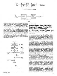
Solving the optimization problem of (1) and (2) for the network of “fig. 1” will lead to four PMUs at buses 2, 7, 10 and 3, hence we have:
_______________________________________________________________
This work is supported by Center of Excellence in Power System Management and Control, Department of Electrical Engineering, Sharif University of Technology, Tehran, Iran.
978-1-4244-4813-5/10/$25.00 ©2010 IEEE
Figure 1. IEEE 14 bus system [7]
“Fig. 1” shows the IEEE 14 bus system with optimal places of PMUs. Now we can island this network to restore the system in a short time.
III.
POWER SYSTEM ISLANDING FOR RESTORATION
For this purpose we should assume some constraints. Our first constraint is that each island should have at least one generator and one PMU and one load. Hence to minimize restoration time, first we should choose the maximum possible islands “m” at the first step that m is defined as:
Figure 2. IEEE 14 bus system after substituting buses connected to transformer with an equal bus
Now we define two concepts here: 1- Central bus: the main bus of each island. In our algorithm it has a generator or a PMU or a load or a combination of these elements. 2- Boundary lines: the lines between the islands which are open when the network works in islanding condition. The “islands vector” at the first step is defined as:
That has a central bus at each row, where matrix B is “network buses vector” and is defined as: In which Ui and Vi are defined as:
And matrix G is an upper triangular matrix and is defined as:
And Wi was defined at (3). The second constraint is that the buses at the two ends of a transformer should be in the same island to make all islands independent, hence we will substitute these buses and elements connected to them like generators and loads with an equivalent bus with equal generator and load capacity. Performing this to the network of “fig. 1” will lead to the equivalent network of “fig. 2”
To define G we assumed that the first term in (6) is minimum among three terms, hence the number of islands at the first step is equal to the number of generators. If our assumption was wrong, we can simply substitute Ui with the minimum one at G arrays. Using (6) for the network of “fig. 2” we have:
this procedure until the constraint of (12) will be satisfied for all islands. For the 14 bus network we assumed that minimum generation of each generator is 10% of its generation, hence (12) is satisfied for the both islands of figure 3. And network bus vector B and matrix G could be found as:
2- All islands should be observable
Hence the islands vector at the first step could be calculated from (10) as:
At the next step we should allocate connected buses to the boundary lines of previous step’s islands that are not belong to the other islands to the islands as follows:
We should continue the allocation process until all buses would be allocated to the islands as follows:
In which Aj is the network connectivity matrix of (5) for island j and Wj is the binary variable vector of (3) for island j and k is the number of buses for that island. If the above equation was satisfied in all islands, they are all observable, else we should form matrix R as follow:
In which AO is the network connectivity matrix of (5) that has here u rows and u is the number of unobservable buses in all islands and is equal to the sum of zero arrays in the left side of (13) for all islands. The diagonal matrix O that we called “PMU installation matrix” is defined as:
“Fig. 3” shows the final allocation of buses to islands for the main network (14 bus network of “fig. 1”). Now we should check two other constraints: 1- Load supplying for minimum generation of all islands:
And Wi was defined at (3). Each row of R is related to an unobservable bus and has a nonzero element that can make the unobservable bus observable.
In which j represents island’s number. We should check the above equation for all islands and if there was any island whose load can’t consume the island’s minimum generation (if it consists), we should search between the load buses of other islands that are connected to the boundary lines of that island which eliminating these buses from its previous islands, would not disturb satisfactory of (12) for those islands. If there was not any island with this condition, we should merge this island with one of its neighbors that had the biggest difference between load and minimum generation. We should continue Figure 3. IEEE 14 bus system after islanding
Now we should move the unobservable buses to the islands that the PMU installed bus belongs to. And we should continue this procedure until all buses become observable. For the first island of 14 bus network we have:
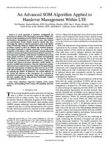
for restoration in which its all buses remain observable. Now we apply this algorithm on New England 39 bus system. “Fig. 4” shows the result.
Hence the buses 1, 5 and 11 are unobservable in the first island, for the second island we have:
Figure 4. New England 39 bus system [8] after islanding
For the second island the only unobservable bus is the bus number 14. now we should find the matrix R, by finding matrix O and AO:
It’s obvious from “fig. 4” that we can divide the 39 network to 9 islands to restore the system quicker after a black out and all buses in islands are observable. IV.
CONCLUSIONS
This paper represents a restoration algorithm based on dividing network to separate islands for a quick restoration. the algorithm divides network in a way that all islands will remain observable with phasor measurements units (PMUs). Results are given for the different size systems: The New England 39 bus system can be divided into nine islands for restoration but the IEEE 14 bus system can’t be divided because of its topology . REFERENCES [1]
Hence the matrix R will be as follow:
[2] [3]
[4]
Rows of matrix R represent observability condition of buses 1, 5, 11 and 14. As we can see the bus number 2 makes buses 1 and 5 observable and the bus number 11 makes bus 10 observable and bus number 14 makes bus 13 observable. Hence we should move the unobservable buses to the islands as explained above. Because both buses 1 and 2 are the central buses of their islands, we can’t move them and hence we should merge these two islands to make all buses observable. Hence we couldn’t divide the IEEE 14 bus network to islands
[5]
[6]
[7] [8]
M. Adibi, P. Clelland, L. Fink, H. Happ, R. Kafka, J. Raine, D. Scheurer, F. Trefny, “Power system restoration – a task force report,” IEEE Transactions on Power Systems, Vol. PWRS-2, No. 2, May 1987, pp. 271 - 277 M. Adibi, L. H. Fink, “Power systemr restoration planning,” IEEE Transactions on Power Systems, Vol. 9. No. 1, February 1994,pp. 22-28 S. Chakrabarit, E. Kyriakides, D. G. Eliades, “Placement of synchronized measurments for power system observability,” IEEE Transaction on Power Delivery, vol. 24, NO. 1, JANUARY 2009, pp. 12-19 B. Xu, A. Abur, “Observability analysis and measurement placement for system with PMUs” Power Systems Conference and Exposition 2004. IEEE PES, vol.2, 10-13 OCTOBER 2004, pp 943 - 946 vol.2 D. Dua, S. Dambhare, R.K Gajbhiye, S.A. Soman, “Optimal multistage schedualing of PMU: an ILP approach,” IEEE Transaction on Power Delivery, vol. 23, OCTOBER 2008, pp. 1812-1820. B. Wang; D. Liu; L. Xiong, “An improved ant colony system in optimizing power system PMU placement problem,” Power and Energy Conference, 2009, APPEEC 2009, Asia-Pacific, 27-31 MARCH 2009, pp 1-3 http://www.ee.washington.edu/research/pstca/ http://psdyn.ece.wisc.edu/IEEE_benchmarks.