In J. Gu (Editor), Proceedings of the Third Interational Confernece on Systems Science and Systems Engineering (ICSSSE'98), Beijing China, pp 75--80, Scientific and Technical Documents Publishing House, Beijing, China, 1998.
An Object Oriented Modelling Integration Framework In Distribution Systems Shi Ping WANG1, Gee Kin YEO2, and Kim Leng POH3 1
Kent Ridge Digital Labs 21 Heng Mui Keng Terrace Singapore 119613 Email:
[email protected] 2
Department of Information Systems & Computer Science National University of Singapore Lower Kent Ridge Road Singapore 119260 Email:
[email protected] 3
Department of Industrial & Systems Engineering National University of Singapore 10 Kent Ridge Crescent Singapore 119260 Email:
[email protected]
Abstract This paper introduces an Object-Oriented Model Integration (OOMI) framework and its application in a practice distribution system. The genus graph of Structured Modelling is extended to represent sequence and scheduling models. A heterogeneous integration from one allocation model and one scheduling model is implemented in OOMI.
1. Introduction Physical distribution presents challenges, both for management and for operational research, because it consists of a number of functional departments (transportation, inventory, warehousing, etc.), each managed somewhat autonomously [1]. Usually, optimal results in a functional department are not optimal in a global strategic sense. Attainment of corporate goals requires co-ordination or integration of distribution decisions. Usually, various modelling approaches, model representations and algorithms are applied in different departments. Therefore, heterogeneous model integration will be required to support the upper level decisions and global optimisation in distribution systems. This paper involves modelling and model integration of a physical distribution system. The distribution planning
-75-
includes two stages: warehouse (depot) allocation and vehicle scheduling. The objective is minimisation of total distribution time with fixed time window and storage capacity constraints. If the two models execute independently, optimality of the total distribution time is not guaranteed. The Object-Oriented Model Integration framework (OOMI) [2] pertains to heterogeneous model integration. The framework includes an internal model representation called Object-Oriented Model Representation (OOMR) [3] and a set of integration operations based on the graphic representation (external representation) of Structured Modelling (SM) [4]. The framework connects schema integration and process integration [5] via an object-oriented model representation as an intermediary. Structured Modelling [4] provides a uniform model representation for different model type at concept level, but lacks of a mechanism to determine a suitable algorithm for operating on a structured model. In OOMR, a model type will be derived from inheritance of model class hierarchy for a given model template. A specific solver can be specified to a given model type. When two or more model schemas with different model types are integrated, process integration at solver level is required. Three types of process integration proposed by Kotteman
[6] and Dolk [5] in terms of variable correspondence and process synchronisation. A suitable tactic of process integration will be derived from properties of joints and model schemas to be integrated in OOMI framework. This paper introduces the principle of OOMI and the application of OOMI in an integration of an allocation model and a scheduling model. The example illustrates that the OOMI framework is an efficient tool for heterogeneous model integration.
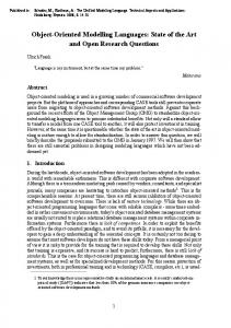
2. Problem Description We consider a distribution environment in which there are several depots (warehouses centre) that serve a set of customers. A depot can serve more than one customer, but one customer is assigned to only one depot. A warehouse in a depot stores several types of items. A large fleet of vehicles is organised into various subgroups, based on their functionality, with individual set of items called VLC (Vehicle Loading Configuration). A VLC contains a list of patterns of item type and quantity to be carried by a vehicle. Different vehicles may have the same VLC. A customer may demand a set of VLCs. The goal is fulfil the demand of the customers in the shortest possible time. The service time for different customers is constrained to a given time window in each depot. The distribution structure is shown in Figure 1, in which C1 to C6 indicate customers, the black diamond illustrates the location of a customer, and the arcs indicate the routes from a customer to a depot.
D1
D2
C3
3.1 Model Schema and Genus Graph in OOMI In OOMR, the model base is organised in a multipleabstraction hierarchy consisting of model type, model templates and model instances. The model type is the top abstraction and represents the mathematical structure in OR modelling paradigm. A model instance just matches to a specific problem. Between the model type and model instance, there is a spectrum of model templates, each of which is a problem abstraction based on an application domain, ranging from the most general abstraction to the most specific one [3]. A model template corresponds to one or more model schema. A model schema is represented in SM’s genus graph at the user interface. SM is based on the idea that every model can be viewed as a collection of distinct elements, each of which has a definition that is either primitive or based on the definition of other elements. Elements are categorised into five types: primitive entity (pe), compound entity (ce), attribute/variable (a/va), function (f), and test (t), grouped by similarity into any number of classes called genera [7]. A genus graph is a directed graph representing the dependencies between genera.
The classical SM genus graph does not provide efficient tools to represent sequence and scheduling models. We should extend genus graph with some new features to represent order index, temporal variables and recurrent functions as follows:
C1 C5
Model schemas represented in the genus graph are linked to the internal model representation (OOMR) in OOMI. Hence schema integration and process integration are connected via OOMR as an intermediary.
In OOMI, we extend some SM definitions. Objective (o) as a new genus type is introduced to the model schema in OOMI [2]. The diagrammatic notation of genus graph in OOMI is listed in Table 1.
D3
C6
3. The OOMI Framework
C2
C4 Figure 1. The distribution structure The objective of the distribution planning is to minimise the total service time subject to time-window and storage capacity constraints. The service time consists of travelling time and loading time. The loading time at a depot depends on the scheduling of vehicles at the depot and the number of vehicles assigned to the depot. Hence an assignment based solely on the shortest distance from customer location to deports will not necessarily yield the desired global optimal solution. The problem here is an interdependent two-stage decision problem. The two subproblems belong to different model types, namely, allocation and scheduling. OOMI will be used to integrate heterogeneous models.
-76-
Order entity:
pe or ce with a subscript represents an order entity list; Temporal attribute: an a or va with a superscript t represents that it obtains the value at time t; Select function: a diamond illustrates a variable to select a value according to given condition; Sorting function: parallelogram demonstrates a function to sort a value list and to return the largest or smallest value; Recurrence: a dash line with arrow describes recurrence between two temporal attributes. At next time t+1, values at t-1 will be replaced by current value at t.
If both integrating schemas are heterogeneous and joints are heterogeneous joints too, then the integration is a Concatenation of two model schemas. For a Concatenation, the solver is a process to control the individual processes corresponding to each model’s solver.
Table 1. Diagrammatic notation of genus graph Diagrammatic Notations
Genus Type and dependence Entity Attributes
If both integrating schemas are heterogeneous and all genera of one schema are joined to the other, the integration is an Embedding of two model schemas.
Variables Function
4. Problem Modelling
Objective Test
Although the two problems are interdependent, we first decompose them into two independent problems to give SM representations individually, then integrate them in OOMI.
Calling chain (from the lower to the higher) 3.2 Model Schema Integration Schema integration is implemented by joining genera based on the genus graph of the structured model schema in OOMR. An integrated model schema will easily be constructed through operating genera on the genus graph. A model schema corresponds to a model template class which is used to identify whether two model schemas are homogeneous or heterogeneous. A joint in an integrated schema is generated by specifying two genera to be joined, one from each schema. The types of genera to be joined and joining approaches will determine the properties of the joints. The joints are classified into three types: homogeneous joints, homoheter joints and heterogeneous joints [2]. Model schema integration is classified based on the properties of joints. Different schema integration will create different model template classes and imply different process integration. There are four kinds of schema integration: Amalgamation, Combination, Concatenation and Embedding in OOMI [2]. When two or more model schemas are homogeneous and all joints are homogeneous joints, the integration is an Amalgamation. When two homogeneous model schemas are amalgamated into another homogeneous model schema, the solver will be exactly the same for the integrated model schema as for each of the integrating schemas. The model template is the same for the integrated schema and the individual integrating schemas.
4.1 Assignment There are N depots to serve M customers. Assume that a depot has W warehouses. Each warehouse has a number of items. Suppose that a customer has V vehicles. Each vehicle has a VLC that configures loading items with quantity on a vehicle. Different vehicle may have the same VLC. A fleet of vehicles that serves one customer may contain more than one VLC. The problem is to assign customers to appropriate depots so that the service time of all customers is the minimised under capacity constraint and time limitation. To formulate the problem, we use the notations as follows: Indices: i: subscript for customers j: subscript for depots k: subscript for items l: subscript for warehouses v: subscript for vehicles Parameters: Cjk: quantity of item k available at depot j, j=1,N Qik: quantity of item k required by customer i, i=1,M Tj: time window set for depot j tij: travelling time from customer i to depot j, Lij: loading time of customer i at depot j Variables: xij: variable xij=1 if customer i is assigned to depot j; 0 otherwise. Formulation: min
When both integrating schemas are homogeneous, and at least one joint is a homo-heter joint, the integration is a Combination. In this case, a new model template class needs to be created. The solver associated with the integrated model may be a single process or multiple individual processes.
-77-
∑∑ j
Aij*xij
i
N
s.t.
∑ j =1
xij=1
(M1)
time. The objective is to reduce idle time as much as possible.
M
∑
Qik xij ≤ Cjk (Capacity constraint)
i =1
M
∑
Aij xij ≤ Tj (Time Window constraint)
i =1
xij =0 or 1, i=1,n; j=1,m
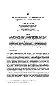
Here, Aij= Lij+ lg(tij) is the service time of depot j for customer i, (tmax= lg(tij), the largest travelling time is selected). Consider the problem of depot-customer assignment (M2). We focus on two entities: Depot and Customer. Create a compound entity: Assignment. Attributes include storage capacity (storage) of Depots, demand quantity (demand) of Customer, service time (ServTime) and assigned value (assigned), which is variable, of t_TW >=
totTime
t_Cap >=
demand
serv Time
assigned
storage
Assignment
Depot
Customer
Assignment. The objective is genus (totTime). The Capacity constraint and Time Window constraint are represented in test genera: (t_Cap) and (t_TW). The genus graph of the above structure model is shown in Figure 2.
Suppose Vl vehicles are assigned to warehouse l, in which there are Pl patterns. nxl vehicles share the same pattern x at warehouse l. Every pattern has a loading time L(px). When different vehicles change over, there are idle time I(px, px+1). The workload of warehouse l (Ωl) is the summation of all loading time and idle time in terms of the number of vehicles (Vl) assigned to the warehouse l. Pl
Ωl = ∑{nxl * L( px ) + (nxl − 1) I ( p x , p x+1 )}
(M2)
x
s.t. clk ≥ nxl qxk ( k=1, Kx) Here nxl and Pl are variables subject to constraint of capacity quantity and balance workloads among opened warehouses. qxk is quantity of item k in pattern x, and clk is quantity of item k in warehouse l. The problem M2 aims to determine a sequence of patterns at each warehouse. A structured model will have Warehouse and Pattern as primary entities. We create a compound entity: Sequence. It will have a variable Vnum (nxl), denoting the number of vehicles with the same pattern to be loaded at one warehouse and an attribute idle time id_time denoting I(px, px+1)) in M2. Loading time L(px) is denoted attribute genus (ld_time) in genus graph. qxk is denoted as attribute genus (qun) of Pattern. clk is denoted as attribute genus (stor) of Warehouse. The genus graph of M2 is represented in Figure 3.
t_TW >=
min{max workload}
Figure 2. Genus graph of depot-customer assignment
stor
id_ time ld_time
t_Cap