An open extensible tool environment for Event-B? Jean-Raymond Abrial1 and Michael Butler2 and Stefan Hallerstede1 and Laurent Voisin1 1
ETH Zurich Switzerland {jabrial,halstefa,lvoisin}@inf.ethz.ch 2 University of Southampton United Kingdom
[email protected]
Abstract. We consider modelling indispensable for the development of complex systems. Modelling must be carried out in a formal notation to reason and make meaningful conjectures about a model. But formal modelling of complex systems is a difficult task. Even when theorem provers improve further and get more powerful, modelling will remain difficult. The reason for this that modelling is an exploratory activity that requires ingenuity in order to arrive at a meaningful model. We are aware that automated theorem provers can discharge most of the onerous trivial proof obligations that appear when modelling systems. In this article we present a modelling tool that seamlessly integrates modelling and proving similar to what is offered today in modern integrated development environments for programming. The tool is extensible and configurable so that it can be adapted more easily to different application domains and development methods.
1
Introduction
We consider modelling of software systems and more generally of complex systems to be an important development phase. This is certainly the case in other engineering disciplines where models are often produced in the form of blueprints. We also believe that more complex models can only be written when the method of stepwise refinement is used. In other words, a model is built by successive enhancement of an original simple “sketch” carefully transforming it into more concrete representations. As an analogy, the first sketchy blueprint of an architect is gradually zoomed in order to eventually represent all the fine details of the intended building. On the way decisions are made concerning the way it can be constructed, thus yielding the final complete set of blueprints. We believe that formal notation is indispensable in such a modelling activity. It provides the ?
This research was carried out as part of the EU research project IST 511599 RODIN (Rigorous Open Development Environment for Complex Systems) http://rodin.cs.ncl.ac.uk.
foundation on which building models can be carried out, similar to the formal conventions that are used when drawing blueprints. Simply writing a formal text is insufficient, though, to achieve a model of high quality. However, we cannot test or execute a model to verify that the model has the properties that we demand of it. Similarly, we cannot open a window in the blueprint of a building. The only serious way to analyse a model is to reason about it, proving in a mathematically rigorous way that the properties are satisfied. In order for formal modelling to be used safely and effectively in engineering practice, good tool support is necessary. Present day integrated development environments used for programming do carry out many tasks automatically in the background, e.g. [13], and provide fast feedback when changes are made to a program text. In particular, there is no need for the user to start processes like compilation. A program is written and then run or debugged without compiling it. We present a tool for Event-B [3] that applies these techniques used in programming to formal modelling. Instead of compilation, we are interested in proof obligation generation and automatically discharging trivial proof obligations. Instead of running a program we reason about models or analyse them. Verification by proof is not restricted to modelling. It has a long tradition in programming methodology, too, e.g. [17]. Software tools that support formal verification methods in programming have been developed, e.g. [7, 14]. We mention [7], in particular, because the Boogie architecture presented in the article provides characteristics similar to the Event-B tool. We quote two points from [7] about Boogie and present our view of them: (1) “Design-Time Feedback”. The tool is very responsive and provides almost immediate feedback that easily relates to the program, (resp. model). (2) “Distinct Proof Obligation Generation and Verification phases”. This allows decoupling the development of the programming (resp. modelling) method and prover technologies. It also allows the origin of a proof obligation to be traced easily. This is particularly important when proofs fail. The third point in the list describing Boogie in [7] is “Abstract Interpretation and Verification Condition Generation”. The corresponding problem does not exist in the Event-B notation because it has been designed to be very close to the proof obligations by means of which we reason about Event-B. Technical difficulties encountered in Event-B stem more from the support of refinement and from the requirement that proof obligations appear transparent to the user. By transparency we mean that the user should look at the proof obligation as being part of the model. When a proof obligation cannot be proved, it should be almost obvious what needs to be changed in the model. When modelling, we usually do not simply represent some system in a formal notation. At the same time we learn what the system is and eliminate misunderstandings, inconsistencies, and specification gaps. In particular, in order to eliminate misunderstandings, we first must develop an understanding of the system. The situation is quite different when programming. When we start programming we should already understand what we are implementing. We do not look any longer at the system as a whole
but only at the parts that we have to implement, and our main concern is doing this correctly. The task of a tool is to point out programming errors to the user. In this article we focus on the Event-B tool. This tool is implemented on top of the RODIN open tools kernel [24] which is developed alongside the Event-B tool. The motivation and background of the RODIN open tools kernel is discussed in Section 1.2. 1.1
Existing Tools for Modelling and Proof
We review a selection of formal modelling tools. It is not intended to be complete but to explain the kind of problems that we try to overcome with the Event-B tool described in this article. The use of general purpose theorem provers with modelling notations like Z [10, 29], Action Systems [4, 19], or Abstract State Machines [6, 9] usually requires a lot of expert knowledge in order to make efficient use of them when reasoning about formal models. This is not a problem of bad design of the theorem prover, but more a problem of bridging the gap between the notation and the logic underlying the theorem prover. General purpose theorem provers are well-suited to proving mathematical theorems in mathematical domains. The main problem solved by the theorem prover is to provide efficient ways to prove theorems. They are not specifically geared for modelling or the typical proof obligations associated with modelling. Theorem provers do assume that the problems to be proved, i.e. the proof obligations, are stated by the user and their proofs as such matter to the user. However, if the main interest of the user is modelling, the user is more concerned with understanding and learning about a model than with the proofs. In particular, generation of the proof obligations should be build into the tool to free the user from tedious work of writing them explicitly. In addition, we expect such a tool to be extensible and adaptable to cope with new and changing applications. This is not an issue with a general purpose theorem prover because proof obligation generation is manual anyway. In the Event-B tool we ensure that proof obligation generation remains extensible and adaptable. Isabelle [23, 30] has been used with Z [10]. Although well-integrated the main problem remains that the user must explicitly specify proof obligations and is responsible for maintaining them. Another problem is that the user must understand the Isabelle logic as well as that of Z. To some degree this is alleviated by the Isar language [22] that extends Isabelle with more legible proofs. Similarly, abstract state machines (ASM) have been used with the KIV theorem prover [6]. The refinement theory used with ASM is stated in KIV and the user has to state the relevant theorems (proof obligations). When dealing with large models the amount of proof obligations is simply to high to load the user with this task [5]. Our tool overcomes these problems by maintaining proof obligations and by providing a prover that is tailored for first-order logic and set theory (which are the basic mathematical theories of Event-B). In the design of the tool great care has been taken to easily relate proof obligations to a model, so that the user can quickly return to the model when a proof fails. The prover interface has also been designed to appear as natural as possible to the user. It
gives a graphical representation of a sequent calculus for classical logic that has been further developed from the Click’n’Prove tool [2]. The major shortcoming of Click’n’Prove is that it is built on top of a theorem prover that executes proof scripts. As a consequence, feedback to the user is slow. In addition, the user must explicitly start tools to type-check a model, or generate proof obligations for it. Because the proof obligation generator has been developed for models of sequential programs with the B-Method [1], some proof obligations have variables renamed or are rewritten to a point where they are difficult to relate to the model. This violates our requirement for transparency. Following the experience with Click’n’Prove, we have also simplified Event-B (see Section 2) so that it does not hinder the design of a transparent proof obligation generator. In the Event-B tool, models are stored in a repository and manipulated like spread sheets. Furthermore, all elements of a model (e.g. invariants, axioms) are named. This makes it possible for the tool to analyse models differentially, only generating proof obligations when necessary. The proof obligations are connected to the model by referring to involved repository elements. The Z/EVES system [26] has a graphical front-end for Z specifications. It has automatic support for type-checking and some related properties. Although its prover is part of the tool, the user is responsible for stating relevant proof obligations. Z/EVES mostly provides a good interface for entering models graphically but less so for reasoning about them. The approach of embedding a modelling notation into a general purpose theorem prover [10] like Isabelle [23] or Coq [8] provides a strong logical foundation. This is very satisfactory from a logicians point of view. From an industrial point of view, logical soundness is only one design consideration. We also need reactivity, i.e. immediate feedback, speed, and a notation and logic that is familiar to the user of the tool. This is very difficult to achieve in embedded designs. In the area of safety-critical embedded software, the approach of directly implementing provers has been proved fruitful. The Atelier B tool [11] has been used in large scale industrial projects, e.g. [5]. 1.2
The Significance of Extensibility and Configurability
We take the view that no one tool can solve all our development problems and that it is important to apply a range of tools in a complementary way in rigorous development. For example, it makes sense to apply model checking as a pre-filter, before applying a theorem prover to a proof obligation. Similarly the use of a diagrammatic views (e.g., UML) of a formal model can aid with construction and validation. Many analysis tools, such as model checkers, theorem provers, translation tools (e.g., UML to B and code generators), have been developed, some of which are commercial products and some research tools. However a major drawback of these tools is that they tend to be closed and difficult to use together in an integrated way. They also tend to be difficult for other interested parties to extend, making it difficult for the work of a larger research community to be combined. Our aim with the RODIN open tools kernel is to greatly extend the state of the art in formal methods tools, allowing multiple parties to integrate
their tools as plug-ins to support rigorous development methods. This is likely to have a significant impact on future research in formal methods tools and will encourage greater industrial uptake of these tools. As well as supporting the combination of different complementary tools, openness and customizability is very important in that it will allow users to customize and adapt the basic tools to their particular needs. For example, a car manufacturer using Event-B to study the overall design of a car information system might be willing to plug some special tools able to help defining the corresponding documentation and maintenance package. Likewise, a rocket manufacturer using Event-B might be willing to plug a special tool for analysing and developing the failure detection part of its design.
2
The Event-B Method
Event-B is defined in terms of a few simple concepts that describe a discrete event system and proof obligations that permit verification of properties of the event system. We present the notation using some syntactical conventions. The keywords when, then, end, and so on, are just delimiters to make the textual representation more readable. Introduction of a syntax in the definition of the notation would make it much more difficult to extend the notation, e.g. by introducing probabilities [21]. An Event-B model consists of contexts and machines. In this description we focus on machines. A complete description of Event-B can be found in [3]. Contexts contain the static parts of a model. These are constants and axioms that describe the properties of these constants. Machines contain the dynamic parts of a model. A machine is made of a state, which is defined by means of variables. Variables, like constants, correspond to simple mathematical objects: sets, binary relations, functions, numbers, etc. They are constrained by invariants I(v) where v are the variables of the machine. Invariants are supposed to hold whenever variable values change. But this must be proved first (see Section 2.1). Besides its state, a machine contains a number of events which show the way it may evolve. Each event is composed of a guard and an action. The guard is the necessary condition under which the event may occur. The action, as its name indicates, determines the way in which the state variables are going to evolve when the event occurs. An event may be executed only when its guard holds. Events are atomic and when the guards of several events hold simultaneously, then at most one of them may be executed at any one moment. The choice of event to be executed is non-deterministic. Practically speaking, an event, named evt, is presented in one of the three following simple forms: evt = b begin S(v) end evt = b when P (v) then S(v) end evt = b any t where P (t, v) then S(t, v) end ,
where P (. . .) is a predicate denoting the guard, t denotes some variables that are local to the event, and S(. . .) denotes the action that updates some variables. The variables of the machine containing the event are denoted by v. The action consists of a collection of assignments that modify the state simultaneously. An assignments has one of the following three simple forms: Assignment x := E(t, v) x :∈ E(t, v) x :| Q(t, v, x0 )
– – –
Before-After Predicate x0 = E(t, v) x0 ∈ E(t, v) Q(t, v, x0 ) ,
where x are some variables, E(. . .) denotes an expression, and Q(. . .) a predicate. Simultaneity of the assignments is expressed by conjoining the before-after predicates of an action. Variables y that do not appear on the left hand side of an assignment of action do not change. Formally this is achieved by conjoining y 0 = y to the before-after predicate of the action. Note, that Event-B requires actions to be feasible under the guard of the corresponding events. For instance, for the non-deterministic assignment we must prove I(v) ∧ P (t, v) ⇒ (∃ x0 · Q(t, v, x0 )) , where I(v) is the invariant of the machine and P (t, v) the guard of the event. In order to be able to provide better tool support invariants, guards, actions are lists of named predicates and assignments. These names can be used to refer to these objects from within the documentation of a machine. But foremost, these names are used to identify all objects and provide helpful information about the origin of proof obligations in the prover interface. The different predicates in the list are implicitly conjoined.
2.1
Consistency of a Machine
Once a machine has been written, one must prove that it is consistent. This is done by proving that each event of the machine preserves the invariant. More precisely, it must be proved that the action associated with each event modifies the state variables in such a way that the modified variables satisfy the invariant, under the hypothesis that the invariant holds presently and the guard of the event is true. For a machine with state variable v, invariant I(v), and an event when P (v) then v := E(v) end the statement to be proved is the following: I(v) ∧ P (v) ⇒ I(E(v)) .
(1)
Note that, in practice we carry out a decomposition of (1) according to the lists of named invariants, guards, and actions. So statement (1) is not the proof obligation the user gets to see. Instead the user sees a collection of simpler proof obligations.
2.2
Refining a Machine
Refining a machine consists of refining its state and its events. A concrete machine (with regards to the more abstract one) has a state that should be related to that of the abstraction by a so-called glueing invariant, which is expressed in terms of a predicate J(v, w) connecting the abstract state represented by the variables v and the concrete state represented by the variables w. Each event of the abstract machine is refined to one or more corresponding events of the concrete one. Informally speaking, a concrete event is said to refine its abstraction (1) when the guard of the former is stronger than that of the latter (guard strengthening), (2) and when the glueing invariant is preserved by the conjoined action of both events. In the case of an abstract event abs and a corresponding concrete event con of the form abs = b when P (v) then v := E(v) end con = b when Q(w) then w := F (w) end , the statement to prove is the following: I(v) ∧ J(v, w) ∧ Q(v) ⇒ P (v) ∧ J(E(v), F (w)) ,
(2)
where I(v) is the abstract invariant and J(v, w) is the glueing invariant. Similarly to (1) the user never gets to see (2) but only the decomposed form. 2.3
Adding New Events in a Refinement
When refining a machine by another one, it is possible to add new events. Such events must be proved to refine a dummy event that does nothing (skip) in the abstraction. Moreover, it may be proved that the new events cannot collectively take control forever. For this, a unique variant expression V (w) has to be provided, that is decreased by each new event. In case the new event has the form: evt = b when R(w) then w := G(w) end , the following statements have to be proved: I(v) ∧ J(v, w) ⇒ J(v, G(w)) I(v) ∧ J(v, w) ⇒ V (w) ∈ N ∧ V (G(w)) < V (w) ,
(3) (4)
where we assume that the variant expression is a natural number (but it can be more elaborate). 2.4
More on Event-B
We have kept the presentation of Event-B concise in order to avoid too many definitions. The article [3] provides more detail. The work on Event-B originates in the Action System formalism [4]. So techniques developed for Action Systems can often also be used with Event-B. However, unlike Action Systems the distinguishing characteristic of Event-B is that the notation has been designed with efficient tool support in mind. Action Systems impose less restrictions in modelling but are difficult to support efficiently by means of a software tool.
3
The Event-B Modelling Tool
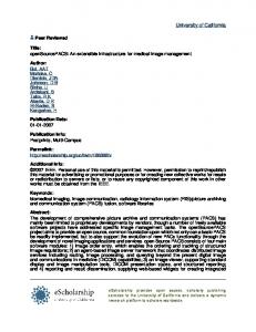
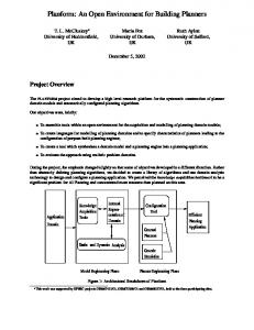
The software tool support for Event-B should not be just another theorem prover. It should be a modelling tool that constrains modelling activity as little as possible. Powerful theorem provers are available [8, 12, 16, 23] but not enough attention has been paid in formal methods to tool support for the modelling activity per se. Traditionally, it is assumed that one begins a formal development with a specification and develops it into a correct implementation. The flaw in this description is that, initially, there is no specification. Writing a specification involves making errors. The Event-B modelling tool takes this into account by being reactive and efficiently supporting incremental changes to models. Development towards an implementation will profit from this, too. In fact, we consider both, writing a specification and implementing it, to be part of the modelling activity. Modelling the Modelling Tool. Although, we do not have translators that could generate plug-ins for the RODIN platform, modelling its components is still useful. As a matter of fact, formal models for most kernel components concerned with Event-B have been created before they were implemented. Some models use Event-B itself, but not all. In this section we also describe the different models that have been created and discuss their use and usefulness. Architecture of the Tool. The tool for Event-B (see Figure 1) is incorporated into the RODIN platform which is an extension of the Eclipse platform. We do not explain Eclipse in this article but only refer to the existing literature [15].
Event−B MUI Event−B SC
Rodin Platform
Rodin Core
Event−B POG
Event−B PUI
Event−B UI
Event−B POM
Event−B Core
Event−B SEQP
Event−B Library Bundles
Event−B AST
Eclipse Platform
Fig. 1. Architectural Overview of the Event-B Tool
3.1
The RODIN Core
The RODIN Core consists of two components: the RODIN repository and the RODIN builder. These two components are tightly integrated into Eclipse based on designs derived from the Java Development Tools of Eclipse. Informal specifications for the repository and the builder have been developed. Their functionality is simple. They are however very dependent on the resources and concurrency model of Eclipse. Neither the repository nor the builder make any assumptions about elements being stored. In particular, they are independent of Event-B. The use of a repository instead of a fixed syntax for the modelling notations makes extending, e.g. Event-B, much easier. It is not necessary to change the syntax or to make extensions inside comments (in order not to change the syntax). The RODIN repository manages persistence of data elements. There is a simple correspondence between data elements in form of Java objects and their persistent storage in XML files. The main design characteristic of the RODIN repository is easy extensibility. The RODIN builder schedules jobs depending on changes made to files contained in the RODIN repository. The builder concept is supplied by the Eclipse platform. It is responsible for automatically launching jobs in the background to achieve higher responsiveness. The builder can be extended by adding new tools to it that keeps derived data elements in the RODIN repository up to date. 3.2
The Event-B Library Packages
Event-B as a whole does not have a syntax that needs to be parsed. Event-B models are kept in a repository. However, the mathematical notation used, e.g., in invariants or guards, has a syntax. It is specified by an attributed grammar that is used to produce the abstract syntax tree (AST) package. The grammar has not been specified in Event-B, although, in principle this should be possible similarly to the technique proposed by Lamport based on TLA+ [18]. The sequent prover (SEQP) library provides the proof engine. It contains the necessary data types, notably the sequent data type, some inference rules and support for tactics. The inference rules have been chosen to represent proof trees that can be easily manipulated in interactive proofs (see Section 3.4). 3.3
The Event-B Core
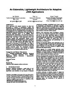
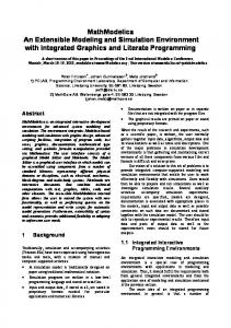
The Event-B Core consists of three components: the static checker (SC), the proof obligation generator (POG), and the proof obligation manager (POM). Their connection is shown in Figure 2 and their purpose is described below. The scheduling of the three components is taken care of by the RODIN builder (see Section 3.1). The static checker for Event-B analyses Event-B contexts and Event-B machines and provides feedback to the user about syntactical and typing errors in them. The mathematical notation of Event-B is specified by a context-free grammar, whereas the rest of Event-B is specified by a graph grammar based
Error Messages
Event−B SC
Unchecked Elements
Event−B POG
Well−formed Elements
Event−B POM
Proof Obligations
Proof Status and Proofs
Fig. 2. Tool-Chain in Event-B Core
on the repository elements. The static checker rejects data elements that do not satisfy the Event-B grammar and produces error messages. It does, however, accept machines and contexts that only partially satisfy the grammar. It filters (and annotates) data elements that are grammatically correct for use by the proof obligation generator that is described in the next paragraph. The static checker can be extended by rejecting more elements and by dealing with new elements that can be added to the repository. The proof obligation generator for Event-B is specified in a simplified notation used with generalised substitutions described in [1]. Compared to the classic B Method [1], Event-B has been simplified with proof obligation generation in mind. The specification of the proof obligation generator does not just serve for its implementation, it has also inspired some simplifications of the mathematical notation. The proof obligation generator produces proof obligations that have already been simplified. This makes them easier to prove automatically and to read in case automatic proof fails. Information about the origin of a proof obligation in a model is also provided in order to easily relate them to the model. The role of the static checker is to filter all elements from the repository that would cause errors in the proof obligation generator. Separating the two yields a much simplified proof obligation generator. This separation is similar to that of front-end and code generator in a compiler. The proof obligation manager keeps track of proof obligations and associated proofs. It offers three functionalities: (1) it matches existing proofs with proof obligations that have changed; (2) it discharges proof obligations automatically (i.e. without user interaction) if possible; (3) it provides an interface for interactive proof, in particular, proof tree manipulation. The functionality referred to in Figure 2 concerns points (1) and (2). Support for interactive proof (3) is used by the graphical user interface (see Section 3.4).
3.4
The Graphical User Interface
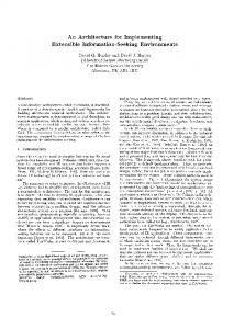
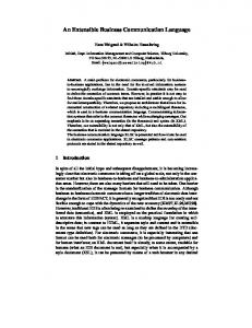
The graphical user interface consists of two parts: one user interface for modelling (MUI) and one user interface for proving (PUI). Figure 3 shows how the core components and the user interface are integrated. The proving user interface
Modelling
Proving Event−B PUI
Error Messages
Event−B MUI
Event−B SC
Unchecked Elements
Event−B POM
Event−B POG
Well−formed Elements
Proof Obligations
Proof Status and Proofs
Fig. 3. The User Interface
does not access proof obligations and proofs directly but uses the services of the proof obligation manager. Appendix A contains a screen shot of the modelling perspective and the proving perspective respectively. The two user interfaces are connected by the tool chain of the Event-B core. They are available to the user in form of Eclipse perspectives between which the user can switch easily. The two perspectives are seamlessly integrated so that it is not suggested that modelling and proving are different activities. The user is intended to perceive reasoning about models as being part of modelling. Proof obligations are equipped with hypertext links so that the user can select instantaneously modelling elements related to that proof obligation. 3.5
On Openness
Integrating formal methods requires a lot of foresight. We would like the integrated method to be used for years to come, estimating where the integrated method could be useful and making reasonable restrictions on the development processes in which it would be used. Next we would develop a tool that would support the integrated method to support its use. Can this work? Being pessimistic about our capacity of predicting the future and the ability to dictate changes, radical or not, to industries that could profit from the integrated method, we choose not to integrate in advance. Instead, we propose an approach where the method from which we depart is open with respect to extensions and even changes. We have the same requirement for the accompanying tool to be open for extension and change. By adopting the open source model, we allow users to integrate their own tools into the tool.
4
Incremental construction of a small example
In this section we outline the construction of a small Event-B model using the tool. Our aim is to illustrate the reactive nature of the support provided by the tool as we incrementally construct the model. The model is of a system for checking registered users in and out of a building. We start the construction of the model by dealing only with registration of users. In the tool we create a new context and introduce a given set U SER in the context. We create a new machine and add a variable register to the machine to represent the set of registered users. We create an invariant to type the register: inv1 register ⊆ U SER We also create an event to add a new user to the register: Register = b any u where u ∈ U SER \ register then register := register ∪ {u} end Notice that the guard of this event ensures that the new user is not already in register. With the above elements (set U SER, variable register, invariant inv1 and event Register) added to the project, the only error message we get is that the register variable has not been initialised. This is remedied by adding the action register := ∅ to the machine initialisation. The resulting model results in 2 proof obligations, both of which are automatically discharged. Now we add variables to represent the set of people who are in the building (in) and those that are outside the building (out). These are typed through the following invariants: inv2 in ⊆ register inv3 out ⊆ register We ensure that in and out are initialised to be empty. We have an obvious requirement that a user cannot be simultaneously inside and outside the building so we add a further invariant: inv4 in ∩ out = ∅ The resulting model now gives rise to 7 proof obligations all of which are discharged automatically. We add events to model users entering and leaving the building. Our first attempt at the Enter event is Enter = b any u where u ∈ out
then in := in ∪ {u} end This event gives rise to 3 new proof obligations, 1 of which is not automatically discharged. Using the proof obligation explorer we can inspect this unproved proof obligation and see that it has hypotheses and a goal as follows: Hyp1 : in ∩ out = ∅ Hyp2 : u ∈ out Goal :
(in ∪ {u}) ∩ out = ∅
Clearly this cannot be proved so either the invariant it is associated with (inv4) is wrong or the Enter event is wrong and one or both need to be changed. The obligation explorer provides hyperlinks to both inv4 and Enter to facilitate any changes to either. In this case we decide that the error is in the Enter operation since we neglected to remove the user from the variable out. We remedy this by clicking on the link to the Enter event and adding the following action to this event: out := out \ {u} This addition results in all 10 proof obligations being discharged automatically. Note that having a proof obligation that is not automatically discharged does not necessarily mean there is an error in the model. It may be that the proof obligation can be proved using the interactive prover. A further requirement on the model is that each registered user must either be inside or outside the building. Our existing invariants are not sufficient to express this property so we add a further invariant: inv5 register ⊆ in ∪ out This addition gives rise to 3 new proof obligations, 1 of which is not automatically discharged: Hyp1 : register ⊆ in ∪ out Hyp2 : u ∈ U SER \ register Goal :
(register ∪ {u}) ⊆ in ∪ out
Clearly this obligation is not provable: if u is not in register, then it is not in in ∪ out. The obligation explorer tells us that this proof obligation arises from both inv5 and the Register event. Inspection of the Register event shows that it adds a user u to register but not to either in or out. We remedy this by deciding that newly registered users should be recorded as being outside the building and adding the following action to the existing Register event: out := out ∪ {u}
The resulting model gives rise to 14 proof obligations, all of which are automatically discharged. We have now completed our construction of the small Event-B model. With the old style tools for B, after constructing the model, we would have separately invoked the proof obligation generator and then the automatic prover. With our new Event-B tool, this is taken care of automatically as we construct the model. Our experience is that by making use of the feedback from the tool as we construct the model, e.g., the unproved proof obligations, we are guided towards construction of a model that has less errors and is more easily proved than if we were to delay any proof analysis until after constructing the full model.
5
Extensions
The RODIN open tools platform will allow other parties to integrate their tools, such as model checkers and theorem provers, as plug-ins to support rigorous development. This will allow many researchers to contribute to the provision of a comprehensive integrated toolset and we believe it will encourage greater industrial uptake of these tools. Along with the open tools platform, RODIN is developing a collection of plug-in tools to be integrated in the RODIN platform [25]. Developing these plug-in tools has two major aims: – To provide extra functionality on top of the core platform to support more fully the application of the RODIN methodology being. – To validate the open architecture of the platform by populating it with a collection of plug-in tools covering a range of functionalities. This section outlines our initial effort at providing a collection of plug-in tools. 5.1
Animation and Model-Checking
The ProB animator and model checker has been presented in [20]. Based on Prolog, the ProB tool supports automated consistency checking of B machines via model checking. For exhaustive model checking, the given sets must be restricted to small finite sets, and integer variables must be restricted to small numeric ranges. This allows the checking to traverse all the reachable states of the machine. ProB can also be used to explore the state space non-exhaustively and find potential problems. The user can set an upper bound on the number of states to be traversed or can interrupt the checking at any stage. ProB will generate and graphically display counter-examples when it discovers a violation of the invariant. ProB can also be used as an animator of a B specification. So, the model checking facilities are still useful for infinite state machines, not as a verification tool, but as a sophisticated debugging and testing tool. The interactive proof process with the B tools can be quite time consuming. We see one of the main uses of ProB as a complement to interactive proof in that errors that result in counterexamples should be eliminated before attempting
interactive proof. For finite state B machines it may be possible to use ProB for proving consistency without user intervention. We also believe that ProB can be very useful in teaching B, and making it accessible to new users. Finally, even for experienced B users ProB may unveil problems in a specification that are not easily discovered by existing tools.
5.2
Unified Modelling Language
The UML-B [27] is a profile of UML that defines a formal modelling notation. It has a mapping to the Event B language. UML-B consists of class diagrams with attached statecharts, and an integrated constraint and action language, called µB, based on the Event B notation. UML-B provides a diagrammatic, formal modelling notation based on UML. The popularity of the UML enables UML-B to overcome some of the barriers to the acceptance of formal methods in industry. Its familiar diagrammatic notations make specifications accessible to domain experts who may not be familiar with formal notations. UML-B consists of: – A subset of the UML - including packages, class diagrams and state charts – Specialisations of these features via stereotypes and tagged values, – Structuring mechanisms (systems, components and modules) based on specialisations of UML packages – UML-B clauses - a set of textual tagged values to define extra modelling features for UML entities, – µB - an integrated action and constraint language based on Event B, – Well-formedness rules The U2B [27] translator converts UML-B models into Event B models. Translation from UML-B into Event B enables the Event B checkers and provers to be utilised. Since the B language is not object-oriented, class instances must be modelled explicitly in the generated B. Attributes and associations are represented as variables whose type is a function from the class instances to the attribute type or associated class. Operation behaviour may be represented textually in µB, as a state chart attached to the class, or as a simultaneous combination of both. Further details of UML-B are given in [27]. Examples of previous case studies using UML-B and U2B are given in [27, 28].
5.3
More
Other plug-ins currently under development in RODIN include a petri-net based model checker for an integration of B and the π-calculus, documentation tools for B models, graphical animation tools, code generation tools and test generation tools.
6
Conclusion
We have presented the architecture of a modelling tool that offers the same comfort for writing models as do modern integrated development environments for programming. We believe that modelling will remain difficult. This does not mean, however, that it is impossible to develop a productive modelling tool. Programming is difficult, too. Still we have very efficient programming tools. But we also have many people who simply got used to the difficulties of programming. Hopefully, they will also get used to the difficulties of modelling when appropriate tools are available. The Event-B tool presented in this article provides a seamless integration between modelling and proving. This is important for the user to focus on the modelling task and not on switching between different tools. The purpose of modelling is not just to write a specification. It also serves to improve our understanding of the system being modelled. The Event-B tool tries to reflect this view by providing a lot of help for exploring a model and reasoning about it. The tool is extensible and configurable because we cannot predict future uses of Event-B. The architecture has been designed to make this as easy as possible to invite users who need a (formal) modelling tool tailor it to their needs. We hope this will make it possible to employ the tool in very different development processes.
Acknowledgements We would like to thank all members of the RODIN project who have contributed to the toolset especially Thai Son Hoang, Cliff Jones, Thierry Lecomte, Michael Leuschel, Farhad Mehta, Christophe M´etayer, Colin Snook and Francois Terrier.
References 1. Jean-Raymond Abrial. The B-Book: Assigning Programs to Meanings. Cambridge University Press, 1996. 2. Jean-Raymond Abrial and Dominique Cansell. Click’n’Prove: Interactive Proofs within Set Theory. In Theorem Proving in Higher Order Logics, volume 2758 of LNCS, pages 1–24, 2003. 3. Jean-Raymond Abrial and Stefan Hallerstede. Refinement, decomposition and instantiation of discrete models. Fundamentae Informatica, 2006. To appear. 4. R. J. R. Back. Refinement calculus, part II: Parallel and reactive programs. In J. W. de Bakker, W.-P. de Roever, and G. Rozenberg, editors, Stepwise Refinement of Distributed Systems, volume 430 of Lecture Notes in Computer Science, pages 67–93. Springer-Verlag, 1990. 5. Fr´ed´eric Badeau and Arnaud Amelot. Using B as a high level programming language in an industrial project: Roissy VAL. In Helen Treharne, Steve King, Martin Henson, and Steve Schneider, editors, ZB 2005, volume 3455 of LNCS, pages 334– 354, 2005.
6. M. Balser, W. Reif, G. Schellhorn, K. Stenzel, and A. Thums. Formal system development with KIV. In T. Maibaum, editor, Fundamental Approaches to Software Engineering, number 1783 in LNCS. Springer, 2000. 7. Mike Barnett, Bor-Yuh Chang, Robert DeLine, Bart Jacobs, and K. Rustan M. Leino. Boogie: A Modular Reusable Verifier for Object-Oriented Programs. In FMCO 2005, volume LNCS. Springer-Verlag, 2005. to appear. 8. Yves Bertot and P. (Pierre) Cast´eran. Interactive theorem proving and program development: Coq’Art: the calculus of inductive constructions. Texts in theoretical computer science. Springer-Verlag, 2004. 9. Egon B¨ orger and Robert St¨ ark. Abstract State Machines: A Method for High-Level System Design and Analysis. Springer-Verlag, 2003. 10. Achim D. Brucker, Frank Rittinger, and Burkhart Wolff. HOL-Z 2.0: A proof environment for Z-specifications. Journal of Universal Computer Science, 9(2):152– 172, February 2003. 11. Clearsy. Atelier B tool homepage. http://www.atelierb.societe.com/. 12. David Detlefs, Greg Nelson, and James B. Saxe. Simplify: a theorem prover for program checking. J. ACM, 52(3):365–473, 2005. 13. Eclipse. Eclipse platform homepage. http://www.eclipse.org/. 14. J.-C. Filliˆ atre. Verification of Non-Functional Programs using Interpretations in Type Theory. Journal of Functional Programming, 13(4):709–745, July 2003. 15. Erich Gamma and Kent Beck. Contributing to Eclipse. Addison Wesley, 2003. 16. Matt Kaufmann and J. Strother Moore. An industrial strength theorem prover for a logic based on common lisp. IEEE Transactions on Software Engineering, 23(4):203–213, 1997. 17. James C. King. A new approach to program testing. In Proceedings of the international conference on Reliable software, pages 228–233, New York, NY, USA, 1975. ACM Press. 18. Leslie Lamport. Specifying Systems, The TLA+ Language and Tools for Hardware and Software Engineers. Addison-Wesley, 2002. 19. Thomas L˚ angbacka and Joakim von Wright. Refining reactive systems in HOL using action systems. In Elsa L. Gunter and Amy P. Felty, editors, Theorem Proving in Higher Order Logics, 10th International Conference, TPHOLs’97, volume 1275 of Lecture Notes in Computer Science, pages 183–197. Springer, 1997. 20. M. Leuschel and M. Butler. ProB: A Model Checker for B. In Keijiro Araki, Stefania Gnesi, and Dino Mandrioli, editors, Proceedings FME 2003, Pisa, Italy, LNCS 2805, pages 855–874. Springer, 2003. 21. Carroll Morgan, Thai Son Hoang, and Jean-Raymond Abrial. The challenge of probabilistic event B - extended abstract. In Helen Treharne, Steve King, Martin C. Henson, and Steve A. Schneider, editors, ZB 2005: Formal Specification and Development in Z and B, 4th International Conference of B and Z Users, volume 3455 of Lecture Notes in Computer Science, pages 162–171. Springer, 2005. 22. Tobias Nipkow. Structured Proofs in Isar/HOL. In H. Geuvers and F. Wiedijk, editors, Types for Proofs and Programs (TYPES 2002), volume 2646 of LNCS, pages 259–278. Springer, 2003. 23. Lawrence C. Paulson. Isabelle: A Generic Theorem Prover, volume 828 of Lecture Notes in Computer Science. Springer Verlag, 1994. 24. RODIN. RODIN project homepage. http://rodin.cs.ncl.ac.uk/. 25. RODIN. Deliverable D16: Prototype Plug-in Tools. http://rodin.cs.ncl.ac.uk/deliverables.htm, 2006.
26. Mark Saaltink. The Z/EVES system. In Jonathan P. Bowen, Michael G. Hinchey, and David Till, editors, ZUM ’97: The Z Formal Specification Notation, 10th International Conference of Z Users, volume 1212 of Lecture Notes in Computer Science, pages 72–85. Springer, 1997. 27. C. Snook and M. Butler. UML-B: Formal modelling and design aided by UML. ACM Transactions on Software Engineering and Methodology, 2006. To appear. eprints.ecs.soton.ac.uk/10169/. 28. C. Snook and K. Sandstrom. Using UML-B and U2B for formal refinement of digital components. In Proceedings of Forum on specification and design languages (FDL03), 2003. 29. J. Michael Spivey. The Z Notation: A Reference Manual. International Series in Computer Science. Prentice-Hall, New York, NY, second edition, 1992. 30. Daniel Winterstein, David Aspinall, and Christoph L¨ uth. Proof general / eclipse: A generic interface for interactive proof. In IJCAI, pages 1587–1588, 2005.
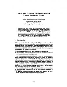
A
The User Interface
Fig. 4. The Modelling Perspective
Fig. 5. The Proving Perspective