An Open Framework to Enable NetFATE (Network Functions At The Edge) A. Lombardo*, A. Manzalini**, G. Schembra*, G. Faraci*, C. Rametta* and V. Riccobene* *
DIEEI, University of Catania, Italy - Email:
[email protected] ** Telecom Italia, Strategy and Innovation-Future Centre, Turin, Italy - Email:
[email protected] Abstract — In the last few years, Software Defined Networks (SDN) and Network Functions Virtualization (NFV) have been introduced in the Internet as a new way to design, deploy and manage networking services. Working together, they are able to consolidate and deliver the networking components using standard IT virtualization technologies not only on high-volume servers, but even in the end user premises. In this context, this paper presents the NetFATE architecture, a platform aimed at putting virtual network functions (VNF) at the edge of the network. This platform is based on free and open source software on Provider Equipment (PE) and Customer Premise Equipment (CPE) nodes, so allowing function deployment simplification and management cost reduction. Finally, the paper proposes a case study, consisting in the implementation of two virtual personal firewalls used by two clients moving between two access points located at the edge of the core network. Index Terms — Software Defined Networking; Network Functions Virtualization; Virtualization Framework; Live Migration; OpenvSwitch; Xen Hypervisor.
T
I. INTRODUCTION
HE new paradigms of Software Defined Networks (SDN) [1] and Network Functions Virtualization (NFV) [2-3] have recently redefined the vision of the Internet, providing network managers with a complete and programmatic control of a dynamic view of the network. The power of SDN is based on its characteristic of decoupling control and data planes, moving the network intelligence to a centralized controller. On the other hand, the emerging technology of NFV introduces an important change in the network service provisioning approach, leveraging standard IT virtualization technology to consolidate many network equipment facilities onto standard servers that could be located in data centers, network nodes and even in the end user premises [2][4]. Moreover, with the NFV paradigm, network functions become software applications that can easily be migrated according to specific policies aimed at optimizing energy efficiency, costs and performance. The combined application of both SDN and NFV is strongly stimulating the interest of Service Providers and Network Operators to make the innovation cycles of networks and services faster and easier, reducing both OPEX (operational expenses) and CAPEX (capital expenses), thanks to the enormous possibilities of making operation processes (e.g. configuration of network devices) automatic, and network functions and services more flexible and cheaper. In fact, decoupling network functions, e.g. middle-box
978-1-4799-7899-1/15/$31.00 ©2015 IEEE
functionalities from dedicated hardware devices, and putting them into Virtual Machines (VMs), NFV enables function and service deployment over the network, and in particular toward the edges of it [5-7]. Moreover, using SDN, traffic control and management functions, like routing, can be moved out of the network nodes and placed on a centralized controller software. Coupling both the approaches, a centralized entity, called Orchestrator, has a complete view of the network to manage the Control Plane and deploy Virtual Network Functions (VNFs). This will represent an enabling factor for a rapid evolution of the dynamic service chain provisioning. Many deployment scenarios of SDN and NFV could be envisioned [8-9], depending on the network segments (e.g., core or edge) and, consequently, on the exploitation time horizon (e.g., medium-long term or short term). Among them, one of the most appealing use cases for Telco Operators and Service Providers is the so-called Virtual Network Function as a Service (VNFaaS). It aims at virtualizing functions of both Customer Premises Equipment (CPE) devices and Provider Edge (PE) nodes, like for example routing, VPN termination, Deep Packet Inspection (DPI), QoS support and Bandwidth differentiation, New-Generation Firewall (NG-FW) and WAN Optimization Control (WOC). According to the general approach of NFV, any router of a Telco network can be virtualized. However, in the short term, the approach of a partial virtualization, intended as a virtualization of only the nodes at the edge of the network, maintaining nodes in the core network not virtualized, seems the most appropriate and widely accepted by Telco Providers. The reason is not only to smooth the investments and assure reliability during the transient period of the first deployment, but also to locate network functions as much close to the users as possible in order to minimize end-to-end latency. Moreover, shifting the focus from the core network to the edges (i.e., to the aggregation, the access or even up to the users’ terminals) simplifies this evolution starting by the micro scale, since by so doing it scales smoothly leading to immediate revenues. This creates a volume and an economic market that will drive investments outside of the network infrastructure boundary and stimulate the advent of new communications paradigms. In this context, this work proposes the NetFATE (Network Functions At the Edge) platform, a proof of concept (PoC) of an NFV framework for the edge of Telco operator networks, deepening on both architectural and implementation aspects. More in detail, Section II illustrates the reference scenario and the NetFATE architecture. Then, Section III presents the
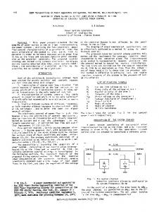
three main NetFATE elements, that is, the Client, the CPE Node and the Orchestrator. NetFATE is then applied to a case study consisting in a virtual firewall migration in order to follow customers on their CPE nodes. Finally, Sections IV draws conclusions and illustrates some future work. II. REFERENCE SCENARIO AND ARCHITECTURE In this section we describe the NetFATE platform architecture. NetFATE is a virtual network platform that implements NFV services at the edge of a Telco network. According to the cloud computing service model classification described in [10][11], it matches three service delivery models: 1) Infrastructure as a Service (IaaS): the NetFATE infrastructure can be supplied by the NetFATE owner to other Telco enterprises to run or migrate their monitoring and management network functions for their users whose traffic is crossing the considered network; 2) Platform as Service (PaaS): NetFATE can be used by other Telco enterprises as a hardware/software platform to create and customize new services to be provided to their customers; 3) Network as a Service (NaaS): the owner of the network infrastructure provides a turnkey solution of virtual network to third-party network operators that can easily setup and sell network services to their customers. NetFATE architecture is compliant with the ETSI NFV reference architectural framework described in [10]. Its main elements, as shown in Fig. 1, are the Customer Premises Equipment (CPE) nodes, also called Home Gateways, the Provider Edge (PE) nodes, or Aggregation Nodes, the Data Centers (DC), and the Coordination Server. The CPE nodes are access gateways (AGs) that can be either home gateways in a residential environment, or medium/high performance routers in an enterprise environment. Exclusively single customers typically use them. On the contrary, PE nodes are the Aggregation Nodes of a Telco IP network, and are typically shared by a high number of customers. PE nodes are connected to each other through the Telco Core Network, that is constituted by high-speed WAN links and high performance forwarding devices. According to the ETSI Specifications [10], both CPE and PE nodes are included in the Network Function Virtualization Infrastructure (NFVI) of NetFATE. The NFVI reference architecture is constituted by three different domains, namely the Compute domain, the Hypervisor domain and the Infrastructure Network domain. The Compute domain provides the computational and storage hardware resources that allow NetFATE physical nodes to host the VNFs. Thanks to the computing and storage virtualization provided by the Hypervisor domain, each VM is able to be migrated from one node to another one to optimize the deployment according to specific performance parameters. Communications between the VMs are provided by the Infrastructure Network domain. A fundamental role in the NetFATE platform is played by the Orchestrator; it runs on a dedicated server and communicates with all the NFVI nodes through the Telco operator IP network. Its goal is to allocate, migrate and terminate VMs running network functions, and consequently
Fig. 1. NetFATE Platform
controlling the traffic paths according to the run-time evolution of the network. More specifically, it is in charge of managing and orchestrating the whole platform, the service chains and the traffic paths according to the amount of traffic crossing the network, the requirements of the Telco operator and the Service Level Agreement (SLA) with the customers. More specifically, for each new traffic flow entering the network, the Orchestrator: 1) decides the NFVI nodes that have to host the service elements that constitute the requested service chain, taking into account the SLA with the customers; 2) instantiates or migrates some VMs in order to provide virtual processing and storage resources to run the requested network functions; 3) realizes the path to connect the VMs that run the requested functions on the NFVI nodes; 4) configures the network interfaces (virtual and hardware) of the nodes that have to forward the new flow, in order to follow a given routing strategy; 5) releases some resources, at the end of a flow, killing VMs that are no longer used by already active flows, and deleting the relative virtual paths. III. NETFATE ARCHITECTURAL APPLICATION In this section we present a free and open source prototype of NetFATE platform, describing hardware and software elements employed to realize our test bed. Although in an embryonic stage, it can be considered as the foundations of a more complex middleware that will be able to provide a wide set of simple and composite network services directly located at the users’ homes and/or at the aggregation nodes at the edge of the core network. In Section III.A we will give a brief overview of the components of the NetFATE architecture; in the same section we will describe the free and open source architecture exploited to realize our prototype including details about the software configuration we used at each network element. Section III.B will focus on an implementation of the CPE nodes, whereas Section III.C will describe the implementation of the Orchestrator server. A. Main NetFATE Elements The NetFATE platform is characterized by three kinds of devices:
HOST O.S. CentOS + Open vSwitch + Xen Hypervisor
Guest VM Network Function: Firewall 10.0.0.55
192.168.1.55
Virtual Switch 1
Virtual Switch 0
IF 1
IF 0
10.0.0.1 10.0.0.10
192.168.1.2 192.168.1.1
IP ROUTER
Public IP
INTERNET
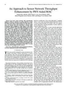
Fig. 2. Networking infrastructure of a CPE node
1) Client: a device that generates/receives traffic flows towards/from the IP public network accessing the Internet through a local access point, the CPE node, that can be a residential or a corporate gateway; 2) CPE Node: a network device deployed in customers’ sites and equipped with two or more network interfaces in order to guarantee Internet connectivity and provide connection to the client devices. In the NetFATE architecture the CPE Nodes are realized with a virtualization framework, in order to create, destroy and migrate virtual machines implementing a set of available network functions, and an virtual switch to provide a switching stack for the hardware virtualization environment; 3) Orchestrator: a remote server that, according to what said so far, mainly provides three functionalities: a.
b.
c.
Software Defined Network Controller: it is the core application of an SDN network, and is based on the OpenFlow protocol to enable configuration and management of real and virtual SDN devices. It acts as a sort of operating system for the network, sending rules to the switches about port forwarding, and choosing optimal paths for application data delivery; Network Function Virtualization Coordinator: it is an application that manages the lifecycle of virtual machines at the home gateways directly communicating to the VMs hypervisor. It is based on the information coming from the Orchestration Engine and the SDN Controller. The NFV coordinator is in charge of creating, migrating and destroying VMs, communicating with the virtual machines hypervisor to send the instructions to execute on the VMs at the CPE nodes; Orchestration Engine: it is the component that gathers information about the network (topology,
number of connected clients, required network services, availability of network devices implementing NFV). According to specific algorithms, it decides how to manage the resources of the network devices; the implemented policy can refer to a wide range of aspects: energy consumption, end-to-end delay between source and destination of a data flow, number of hops of the path, overall number of virtual machines active at the same time, etc. For the sake of simplicity, in the following we will focus on a scenario constituted by two CPE nodes, two Clients and the Orchestrator. Each Client connects to the CPE Node every time it wants to access the public Internet. The CPE Node acts as a local access point providing a DHCP service to the Client. The CPE Nodes are connected throughout the public IP core network to the Orchestrator, a remote server implementing the three features presented above. All the information regarding Clients, Network functions and NFVI nodes are stored in the NFVI Database. With the aim of identifying clients, a captive portal is implemented on each CPE Node. A RADIUS server is installed on the Orchestrator to manage the procedures of accounting, authentication and authorization by using a user authentication procedure based on user name and password. Once a client is authenticated and authorized to access the NetFATE network, its information is sent to the Orchestrator node for managing the virtual machines environment and the routing paths on the underlying SDN network. B. CPE Node Configuration A CPE Node has been realized with a general-purpose computer, equipped with at least two network interfaces, one providing connectivity to client devices belonging to the local area network, and the other connected to the IP core network. As regards the virtualization environment, we can distinguish between the host operating system (this element can be the OS of the host machine or a virtual machine running on the general purpose hardware), and a set of network virtualized functions, i.e. virtual machines created and configured to provide network services made available by the NetFATE platform to the network clients. In our prototype the host OS is CentOS release 6.4, directly installed on the bare metal, whereas the guest virtual machines run light network oriented OSs, such as CentOS, ZeroShell or similar. As virtual machines hypervisor, that is the middleware software enabling both virtual system management and hardware resource sharing with the aim of executing multiple computer operating systems on the same hardware concurrently, we have chosen Xen Hypervisor. This is a free and open-source software, developed by the University of Cambridge Computer Laboratory, available for x86-64, IA-32 and ARM architectures, supporting a form of virtualization known as para-virtualization. Thanks to the para-virtualization paradigm it is possible to obtain a faster execution of the VMs as compared with the traditional approaches; more in detail, Xen Hypervisor permits the virtual machines to share directly the x86-64 hardware without the need to preventively specify the resources to be allocated for the virtualized hardware. Under this perspective the host OS only acts as a console to operate
Table I: NFVI Database – Table of Users USER
Personal virtual firewall 1
Personal virtual firewall 2
Other Virtual Functions
Access CPE node
ID Client 1 ID Client 2 ... ID Client n
1
0
...
1
0
1
...
2
... ...
... ...
... ...
... ...
Last Packet Timestamp
... ...
Table II: NFVI Database – Table of Network Functions Virtual Network Functions
Active
On Home Gateway
Number of Active Users
Personal Firewall 1 Personal Firewall 2 Load Balancer Packet Inspector ... Network Function n
1 0 0 0 ... 0
1 0 0 0 ... 0
... ... ... ... ... ...
Table III: NFVI Database – Table of SDN Controller forwarding rules Fig. 3. An overview of the Orchestrator node architecture
with the virtualization manager, enabling commands as create, destroy and migrate. Finally, OpenvSwitch has been installed on the host OS in order to create and configure SDN-compliant virtual switches. Once created, it is possible to connect both real and virtual network interfaces to the virtual switches, and enable the remote control of the switch by setting up a software-defined controller. The networking infrastructure inside the CPE node is presented in Fig. 2. Each virtual machine has assigned two or more virtual network interfaces and each of them can be connected to a virtual switch. The host OS acts as DHCP server assigning private IP addresses to each new interface when the virtual machine is created. Moreover, virtual MAC addresses are assigned during the virtual machine configuration in such a way that each virtual network function has a set of univocal addresses that will be used by the SDN controller to identify the virtual functions and route the application data packets. C. Orchestrator Configuration The Orchestrator node plays a key role in the overall platform. Its architecture is shown in Fig. 3. It is a remote server implementing the three main functions discussed above in the following way: 1) SDN Controller: this function has been realized by using POX, an SDN python-based controller enabling the management of virtual switches. The behavior of the POX controller is described through a python script that regulates the port forwarding of the virtual switches. More in detail, when a packet coming from a new MAC address is received at the virtual switch running at the CPE node, the virtual device sends a query to the SDN controller in order to know the forwarding rule for the new flow. The SDN Controller will answer to the query by sending the MAC address related to the virtual machine implementing the required virtual network function (a simple example of forwarding table will be illustrated in Table III).
USER
MAC Address
Local IP Address
MAC address of required VNFs
ID Client 1
MAC 1
10.0.0.2
ID Client 2
MAC 2
10.0.0.3
... ID Client n
... ...
... ...
MAC of the VM implementing Virtual Firewall 1 MAC of the VM implementing Virtual Firewall 2 ... MAC of the VM implementing Network Function n
2) NFV Coordinator: this component manages the virtualized network functions. In our prototype it has been realized by using a C++ software implementing a client-server application. The server runs on the Orchestrator node, whereas clients run on the CPE Nodes. The NFV Coordinator is aware of all the client connections, their CPE access nodes, and the required network functions thanks to the use of an Users Database (see Table I) and a Network Functions State Table (Table II). Furthermore, according to this information and the implemented policies, the NFV Coordinator and the Xen Hypervisor communicate to each other according to a client-server paradigm to create, migrate and/or destroy the virtualized NFs. 3) Orchestration Engine: this component implements the business intelligence of the NetFATE platform. In our prototype we used a very simple decision algorithm as illustrated below: for each required service, a virtual machine is run on the access CPE node of the traffic flow requesting it. If a user moves from one site to another site changing his access CPE node, all the VMs implementing the requested network functions are migrated on the new access node. Definition of metrics and algorithms to manage the virtualization framework and the related implementation in dedicated functional blocks are included in future works. IV. CASE STUDY: VIRTUAL FIREWALL MIGRATION In this section we report a case study realized to evaluate the effectiveness of the proposed architecture. We considered a simple NetFATE PoC composed by two client PCs, two
CPE 1
CPE 2
HOST O.S. CentOS + Open vSwitch + Xen Hypervisor
HOST O.S. CentOS + Open vSwitch + Xen Hypervisor Guest VMs NOT ALLOCATED
Guest VMs Personal Firewall 1 192.168.1.55 10.0.0.55 Virtual Switch 1
Virtual Switch 0
Virtual Switch 0
Virtual Switch 1
IF 1
IF 0
IF 0
IF 1
1
2
CLIENT 1 IP ROUTER
INTERNET
ORCHESTRATOR
Fig. 4. Testbed time evolution
CPE nodes acting as network access points and virtual network functions providers, one remote Orchestrator acting as RADIUS authentication and authorization server, SDN controller and NFV coordinator. We created two virtual machines implementing two personal virtual firewalls, required by Client 1 and Client 2, respectively. We will describe what happens when Client 1 accesses the Internet through CPE 1, and then moves to the access point CPE 2 (see Fig. 4 and Fig. 5). As said in the previous section, the Orchestration Engine algorithms are out of the scope of this paper, so in our testbed a very simple policy has been employed, as described below: a.
when the clients are not connected to the network the virtual machines implementing their personal firewall functionalities are turned off;
b.
when a client connects to one of the two available access points, i.e. the CPE nodes of the proposed platform, the related virtual personal firewall is turned on at the access node where the client is connected to;
c.
when the same user changes its Internet access point moving from the CPE 1 node to the CPE 2 node, the latter requests login credentials to the user through the captive portal mechanism, and sends them to the Radius server running on the Orchestrator server; once identified, the Orchestrator migrates the personal virtual firewall from the previous CPE node to the new one;
d.
finally, when the user traffic flow terminates (i.e. there are no packets of it for a certain time period), the Orchestrator arranges the release of virtual resources assigned to its flows.
In order to realize user authentication and flow identification, a VM executing a Captive Portal service is run on each CPE node, in such a way that all users entering the NetFATE network are identified by a login procedure consisting in the insertion of user ID and password. Login information provided by an entering user are sent by the
Captive Portal to the Radius server on the Orchestrator server, in order to check whether the client is authorized or not to access the network. If authorized, the NFVI Users database is updated, that is the ID of the CPE node where the access has been performed is stored in the field ‘Access CPE node’ related to entering client (refer to Table I). Furthermore, user credentials are used by the Orchestrator to derive the needed information from the same database, where the required network functions are listed for each user. In our case study we considered a personal firewall requested by each user. According to this client requirement, the NFV Coordinator establishes whether creating or not a new virtual function communicating to the hypervisor at the CPE nodes. More in detail, when the Captive Portal sends client credentials to the Orchestrator server, the RADIUS server authenticates and authorizes the client and, at the same time, the NFV Coordinator checks the client ID in the User Table in the NFVI Database. For each client a series of Boolean variables specifies if a specific network function, among the ones provided by the network operator, is required or not. Let us suppose that Client 1, that requires personal virtual firewall 1, accesses the network through the CPE 1; the NFV Coordinator checks the client ID in the NFVI Database, finding that it requires personal virtual firewall 1. Once established that a virtual function is required, the NFV Coordinator verifies in the NFs database, Table II, if the related virtual machine is active in the network. If this is the case, the Orchestrator matches the client access gateway and the gateway where the virtual function is running; if the two fields are equal nothing to be done, otherwise, according to our policy, the virtual function is migrated towards the access gateway where the client is connected to. If the virtual machine is not yet active, the NVF coordinator communicates to the access CPE node hypervisor in order to create a new VM with the required virtual function. Let us highlight that the migration consists in the transfer of the only volatile memory (i.e. the RAM) of the virtual machine in order to avoid long transient periods between the connection of the client to the new CPE node and the availability of the network function at the new location. In our prototype the images of all the virtual machines are saved in the hard disk of the Orchestration Server and are made available to the CPE nodes by using Network File System (NFS). The server hosting the Orchestrator implements the NFS daemon processes in order to make the disk images available to its clients, i.e. the CPE nodes. ACKNOWLEDGEMENTS This work has been partially supported by the INPUT (InNetwork Programmability for next-generation personal cloUd service supporT) project funded by the European Commission under the Horizon 2020 Programme (Call H2020-ICT-2014-1, Grant no. 644672), and by the "Programma Operativo Nazionale “Ricerca & Competitività” 2007-2013” within the project "PON04a2_E – SINERGREEN – RES NOVAE – Smart Energy Master per il governo energetico del territorio”.
V. CONCLUSIONS AND FUTURE WORKS This paper presents a PoC of the NetFATE platform, a free and open source platform that deploys network functionalities at the edge of the network. The architecture includes an Orchestration Server, which is the decision maker in terms of allocation of virtual resources and traffic routing, two CPE nodes, i.e. the access points at the edge of the provider core network where the network function virtualization framework is deployed, and two clients, the final users of the architecture. Two simple personal virtual firewall services have been deployed and managed using a simplified allocation policy according to which network services run near the client requiring them; the prototype has been tested to evaluate the effectiveness of the proposed solution. As a future work we plan the implementation of service chains at both CPE and PE nodes. According to this paradigm each user, previously registered to the network, can require a set of network functions (for this scope two or more virtual machines will be used) and an orchestration engine, coupled with the NFV coordinator and the SDN controller, will establish how to manage the virtual network services.
REFERENCES [1]
White paper on “Software-Defined Networking: The New Norm for Networks”, available at https://www.opennetworking.org/. [2] White paper on “Network Functions Virtualisation”, available at http://portal.etsi.org/NFV/NFV_White_Paper.pdf. [3] A. Manzalini et al., “Software-Defined Networks for Future Networks and Services,” White Paper based on the IEEE Workshop SDN4FNS, [4] Network Functions Virtualisation – White Paper #3, “Network Operator Perspectives on Industry Progress,” available at https://portal.etsi.org/ Portals/0/TBpages/NFV/Docs/NFV_White_Paper3.pdf [5] A. Manzalini et al. “Clouds of virtual machines in edge networks,” Communications Magazine, IEEE 51.7 (2013). [6] A. Lombardo, A. Manzalini, V. Riccobene and G. Schembra, “An Analytical Tool for Performance Evaluation of Software Defined Networking Services”, in Proc. of SDNMO workshop, IEEE/IFIP NOMS 2014, Krakow (Poland), May 5-9, 2014. [7] A. Lombardo, A. Manzalini V. Riccobene, G. Schembra, “An Open Architecture for Software Defined Services at the Edge,” EuCNC2014, Bologna, Italy, June 23/26, 2014. [8] ETSI GS NFV 001, “Network Functions Virtualization (NFV): Use Cases”, 10-2013, available at http://www.etsi.org/deliver/etsi_gs/ nfv/001_099/001/01.01.01_60/gs_nfv001v010101p.pdf. [9] ETSI – PoC, “NFV Proofs of Concept,” available at http://www.etsi.org/ technologies-clusters/technologies/nfv/nfv-poc. [10] ETSI GS NFV 002, “Network Functions Virtualization (NFV): Architectural Framework”, 10-2013, available at http://www.etsi.org/ deliver/etsi_gs/nfv/001_099/002/01.01.01_60/gs_nfv002v010101p.pdf. [11] P. Costa, M. Migliavacca, P. Pietzuch and A. L. Wolf, “NaaS: Networkas-a-Service in the Cloud,” in Proc. of Hot-ICE’12, April 24 2012, San Jose, CA.
Fig. 5. Messages exchange during the migration of the client 1 from CPE 1 to CPE 2.