Dec 30, 2010 - ers in [Chrysler, Ford Motor Co., and General Motors 1994]. In response to these re- quirements, the OMAC Application Programming Interface ...
An Open System Framework for component-based CNC Machines John Michaloski National Institute of Standards and Technology Sushil Birla and C. Jerry Yen General Motors Richard Igou Y12 and Oak Ridge National Laboratory George Weinert Lawrence Livermore National Laboratory
This paper describes a framework for open, component-based, manufacturing controllers. The framework is based on the analysis of computer numerically controlled (CNC) machines. The framework includes a control class hierarchy, plug-and-play modules aggregated from the class hierarchy, and a model of collaboration. The framework can be used to build applications that range from a single-axis device to a multi-arm robot. General Terms: Frameworks, Control Additional Key Words and Phrases: API, architecture, classes, CNC, object-oriented
1. BACKGROUND A desire for agile discrete-parts manufacturing has resulted in a need for open controllers implemented with plug-and-play components for cost and performance reasons. Industry requirements for open-control are spelled out in the “Open Modular Architecture Controller” (OMAC) requirements document, originally specified by the Big Three automakers in [Chrysler, Ford Motor Co., and General Motors 1994]. In response to these requirements, the OMAC Application Programming Interface (API) workgroup was formed and has developed the OMAC API specification that adopts an open system framework to enable open controller technology. (See [OMAC API Workgroup ] for more information.) Generally the term framework is used to mean a specification for an integrated set of software components. An open system framework is a framework that promotes interface Permission to make digital/hard copy of part or all of this work for personal or classroom use is granted without fee provided that the copies are not made or distributed for profit or commercial advantage, the copyright notice, the title of the publication, and its data appear, and notice is given that copying is by permission of the ACM, Inc. To copy otherwise, to republish, to post on servers, or to redistribute to lists, requires prior specific permission and/or a fee. c 2000 ACM 00360-0300/00/0300
2
�
OMAC API Machining systems/cells; workstations
Plans
Simple machines; tool-changers; work changers
Processes
Fixtures Axis groups Other tooling Machine tool axis or robotic joints (translational; rotational) Axis components (sensors, actuators)
Control components (pid; filters)
Geometry (coordinate frame; circle) Units (meter)
Measures (length)
Kinematic structure Containers (matrix)
Primitive Data Types (int,double, etc.)
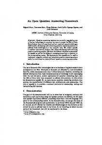
Fig. 1. Manufacturing Controller Class Hierarchy
reuse based on a public interface specification [Johnson 1997]. An open system framework allows integrators to mix and match components from different vendors. With an open system framework, controllers can be built from best value components from best in class services. For parts manufacturing, this ability leads to better integration of process improvements and increased satisfaction of application requirements. In the following sections, we review the OMAC API open system framework, which was designed to be flexible enough to accommodate a broad range of manufacturing control applications. First, an analysis of application domain is presented leading to the definition of an abstract class hierarchy. Next, the concept of a “module” is introduced as a necessary prerequisite for plug-and-play. Following this discussion, module behavioral patterns within the framework are reviewed. Finally, an example of module collaboration is presented. 2. APPLICATION DOMAIN ANALYSIS The primary OMAC API application domain is multi-axis, coordinated motion control typical of Computer Numerical Control (CNC) machines or robots. In addition, process control is necessary to handle input/output, events and auxiliary equipment. Representative controller applications include cutting, manipulation, forming, and grinding. The target range of controller complexity can be quite large – from multiple robotic arms to single axis controllers. This disparity implies that the framework must be scalable and permit portions of the framework to be used. Other controller constraints such as memory limitations and real-time performance also shape the framework. Frameworks use a class hierarchy for domain modeling. Figure 1 portrays the class hierarchy derived from the decomposition of a shop-floor controller. The decomposition of a generic controller into classes spans many levels of abstraction and has elements for motion control and discrete logic necessary to coordinate machining, cut parts, and sequence operations. Classes form the building blocks of the framework. For example, the class definition for “position” can be found throughout the hierarchy. As one moves up the hierarchy, classes broaden their scope to define device abstractions for physical components such as sensors and actuators. As the scope broadens however, objects have no physical equivalents. Objects such as Axis Groups are only logical entities. Axis Groups embody the planning and
A Framework for component-based CNC Machines
�
3
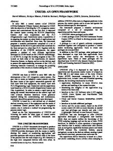
control knowledge needed to coordinate multiple axes. In turn, methods of an Axis Group are invoked by user-supplied Plans. 3. PLUG-AND-PLAY MODEL Plug-and-play on a per-class basis is not really feasible. Instead, a coarser granularity component, which we call a module, is necessary for realizing plug-and-play. The OMAC API framework extracts approximately 20 modules from the class hierarchy. To be plugand-play, a module must satisfy the following requirements: —significant piece of software used in a component-based controller —grouping of similar classes —well-defined API, states, and state transitions —replaceable by any other piece of software that implements the API, states and state transitions. Modules have other secondary characteristics. Modules can be either active or passive based on variations regarding supervision and activation. Modules may provide more functionality than required in the specification. More than one instance of a module may be used in a controller. Modules may be used to build other components. Controllers are built with a set of modules. At the top level, controllers are modeled as a distributed system of concurrently active objects – although in implementation a single thread of execution is possible. Active objects do not need to receive a message to be in the “active” state and govern their execution by internally managing one or more independent threads of control. To reinforce the notion of plug-and-play, we use the term active module in lieu of “active object.” Examples of controller active modules include: (1) Axis modules, which perform servo control of axis motion by transforming incoming motion goal points into setpoints for the corresponding actuators; (2) Axis Group modules, which coordinate the motions of individual axes by transforming an incoming motion segment specification into a sequence of equi-time-spaced setpoints for the coordinated axes; (3) Discrete Logic modules, which implement discrete control logic or rules characterized by a Boolean function that maps input and internal state variables to output and internal state variables; and (4) Task Coordinator modules, which sequence operations and coordinate the various motion, sensing, and event-driven control processes. Active modules may delegate to passive modules that do not possess threads of control and that depend on an active module for the execution of their functions. Examples of passive modules include (1) Kinematic Model modules, which perform coordinate frame transformations, and (2) Control Law modules, which are responsible for servoing calculations to reach commanded setpoints. 4. BEHAVIOR MODEL The behavior of an active module is modeled by a Model, Events, and Finite State Machine (FSM) pattern that is illustrated in Figure 2(a). The source (or generator) of all Events is the Model. This means that the Model contains API, which will trigger Events, which are used by the FSM (which will make calls to the Model’s API’s, which can generate events, ....ad infinitum). The FSM may contain one or more embedded active modules as illustrated in Figure 2(b). Embedding of FSMs leads to recursive event propagation and corresponds to
4
�
OMAC API
Axis Group Model Model FSM FSM Event Event
(a) Active Module Axis Model
FSM Model
Model FSM
FSM
Event
Event
(b) Embedded Active Module
Event
(c) Interacting Active Modules
Fig. 2. Active Module Relationships
the concept of layered FSMs [Harel 1988]. FSMs can be evaluated synchronously at given time intervals or asynchronously on an event-driven basis. Interacting active modules maintain a client-server relationship where a supervisory client commands a subordinate server. To communicate, a supervisory module’s Model makes API calls to other subordinate module’s Models, which will then send events to their own FSM’s as illustrated in Figure 2(c). Overall, event dispatching is both distributed as well as recursive. Such event dispatching contrasts to traditional frameworks characterized by centralized event handling known as inversion of control [Fayad and Schmidt 1997]. FSMs can also be either resident or transient. In the transient case, an FSM can be removed, and then replaced with another FSM. An FSM is transient when, for example, a supervisor issues a new command to the subordinate or when an exception occurs and an exception handling FSM is required. Representation of an FSM can be complex and there is no universal FSM strategy. In light of this situation, OMAC has developed the Control Plan Unit (CPU) module to capture the essentials of an FSM. The crux of the CPU class is a few fundamental methods as seen in the following Interface Definition Language [Object Management Group 1995]: interface ControlPlanUnit { ControlPlanUnit executeUnit(); boolean isDone(); }; The ControlPlanUnit is an example of the Command pattern [Gamma et al. 1994]. To evaluate the current state, an active module invokes the executeUnit() method, which causes the FSM to perform a state evaluation. Examples of modules derived from Control Plan Unit include: (1) Capability, which is a CPU to which the Task Coordinator delegates for specific modes of operation corresponding to traditional CNC operating modes (AUTO or MANUAL); (2) Motion Segment, which is a transient CPU used by the Axis Group module for motion control; and (3) Discrete Logic Unit, which is a transient or resident CPU for discrete logic control. A series of linked CPUs forms a Control Plan. A Control Plan is a general-purpose representation of a control program. OMAC API defines the Control Plan Generator mod-
�
tro lPl an U
nit ()
A Framework for component-based CNC Machines
Control Plan Unit
n io ot gm Se
Motion Segment
tM ex
Control Control Control Plan Unit Control Plan Unit Control Plan Unit Plan PlanUnit Unit
Task Coordinator
tN se
(b)
(a) translate()
(c) executeUnit()
) (d
N10 G01 G91 F10 N20 X10 Y10 Z10 N30 X1 Y1 Z1 N40 M30
ge tN ex tC on
RS 274 Part Program
5
en t()
Control Plan Generator Motion Motion Motion Segment Segment Segment
Axis Group Motion Motion Motion Segment Motion Motion Segment Segment Segment Segment
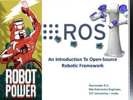
Fig. 3. Collaboration Model
ule, which is responsible for translating programs written in application-specific languages (e.g., CNC RS274D part programs [Engineering Industries Association 1979]) into the more general Control Plan. To enable program translation, OMAC API defines Program Logic CPU to mimic control constructs such as if/then, or while statements. The next section will study the case where a CPU can contain embedded CPUs as a model of collaboration. 5. COLLABORATION Transient CPUs serve as data by being passed between active modules. Subsequently, such transient CPUs then serve as the FSM logic within the behavior model. Figure 3 illustrates the collaboration model as a CPU propagates through a simplified control system. In step (a) the Control Plan Generator module translates a part program written in RS274D into a Control Plan. In step (b) the Task Coordinator uses getNextControlPlanUnit to retrieve a CPU. In step (c) the Task Coordinator does an executeUnit on this CPU. Step (c) may be repeated several times as in the case where the CPU may have to synchronize with lower level modules (e.g., such as waiting until all current Motion Segments have first completed). After synchronization, step (d) occurs whereby the CPU appends a reference Motion Segment CPU onto the Axis Group motion queue using the method setNextMotionSegment. This is an example of an embedded CPU being passed to a subordinate module. Once the Motion Segment CPU is loaded onto the Axis Group queue, it waits for activation. Once activated, the Axis Group periodically calls the Motion Segment CPU executeUnit() method until the isDone() condition is true. 6. CONCLUSION The OMAC API specification employs an open system framework to enable plug-and-play controller technology. Components are defined at a coarse granularity to enable market viability. The OMAC API framework provides a standard way for components to collaborate including provisions for exchanging information, invoking operations on each other, and handling errors. The OMAC API framework is not all-inclusive. The focus of effort has been to develop
6
�
OMAC API
a framework for assembling and reconfiguring modules that the controller community routinely wants to upgrade. At this time, the OMAC API framework discusses, but does not attempt to specify procedures for such issues as conformance, configuring modules, performance evaluation, and resource profiling. REFERENCES Chrysler, Ford Motor Co., and General Motors. 1994. Requirements of Open, Modular, Architecture Controllers for Applications in the Automotive Industry. Chrysler, Ford Motor Co., and General Motors. White Paper – Version 1.1. Engineering Industries Association. 1979. EIA Standard - EIA-274-D, Interchangeable Variable, Block Data Format for Positioning, Contouring, and Contouring/Positioning Numerically Controlled Machines. Washington, D.C.: Engineering Industries Association. FAYAD , M. AND S CHMIDT, D. C. 1997. Object-Oriented Application Frameworks - Introduction. CACM 40, 10, 32–38. G AMMA , E., H ELM , R., J OHNSON , R., AND V LISSIDES , J. 1994. Design Patterns: Elements of Reusable Object-Oriented Software. Addison Wesley, Reading, MA. H AREL , D. 1988. On Visual Formalisms. CACM 31, 5, 514–530. J OHNSON , R. E. 1997. Frameworks = (Components + Patterns). CACM 40, 10, 39–42. Object Management Group. 1995. The Common Object Request Broker: Architecture and Specification, Revision 2.0. Framingham, MA: Object Management Group. OMAC API Workgroup. OMAC API Set. OMAC API Workgroup. See Web URL: http://isd.cme.nist.gov/info/omacapi.