ment of a background-free optical cross-correlation scheme to synchronize two individual mode-locked laser systems of different center wavelengths and ...
THPC160
Proceedings of EPAC08, Genoa, Italy
AN OPTICAL CROSS-CORRELATION SCHEME TO SYNCHRONIZE DISTRIBUTED LASER SYSTEMS AT FLASH S. Schulz∗ , P. Schm¨user, J. Zemella – University of Hamburg, Germany V. Arsov, M. Felber, F. L¨ohl, B. Lorbeer, F. Ludwig, K.-H. Matthiesen, H. Schlarb, B. Schmidt, A. Winter – Deutsches Elektronen-Synchrotron (DESY), Hamburg, Germany B. Steffen – Paul-Scherrer-Institut (PSI), Villigen, Switzerland Abstract The VUV- and soft X-ray free-electron laser FLASH and the planned European XFEL generate X-ray light pulses in the femto-second range. For time-resolved pump-probe experiments, future operation modes by means of laser seeding and for special diagnostic measurements it is crucial to synchronize various laser systems to the electron beam with an long-term stability of better than 30 fs. For this purpose an optical synchronization system is currently being installed and tested at FLASH. In this paper, we report on the progress of the development of a background-free optical cross-correlation scheme to synchronize two individual mode-locked laser systems of different center wavelengths and repetition rates with an accuracy of better than 10 fs. The scheme is being tested by linking a commercial Ti:sapphire oscillator, used for electro-optical diagnostics at FLASH, to a locally installed erbium-doped fiber laser. Later, this laser will be replaced by an end-point of an actively length-stabilized fiber-link distributing the pulses from the master laser oscillator of the machine to lock the diagnostics laser to the optical synchronization system.
curacy.
TWO-COLOR BALANCED OPTICAL CROSS-CORRELATOR The operation principle of such a two-color balanced optical cross-correlator is based on the sum frequency generation (SFG) in a type-I phase-matched nonlinear crystal and the generation of a group delay difference between the two input pulses with the same polarization but different center frequencies using a dispersive material. In our first prototype we use a commercial ultra-short pulse 81.25 MHz Ti:sapphire oscillator with a center wavelength of 800 nm and a home-built erbium-doped fiber laser (EDFL) with a center wavelength of 1550 nm as the timing reference, resulting in a wavelength of 527.7 nm of the corresponding sum frequency.
THE OPTICAL SYNCHRONIZATION SYSTEM OF FLASH The optical synchronization system for FLASH [1, 2] and under consideration for the European XFEL [3] is based on a ultra-stable, mode-locked master laser (MLO) locked to a low-noise RF oscillator generating sub-ps light pulses at the telecommunication wavelength of 1550 nm. The timing information is contained in the precise repetition frequency of 216.66 MHz of the pulse train and distributed via actively length-stabilized fiber links to the remote locations along the accelerator. At these locations, low-level RF signals can be extracted using photo detectors and bandpass filters or Sagnac loops to pick a harmonic of the MLO’s repetition rate. Another application is the use of the distributed light pulses directly, for example for bunch arrival time monitors [4] or after frequency doubling to seed a Ti:sapphire amplifier. One of the key component of the synchronization system is a balanced cross-correlator, because it provides a mechanism to lock different laser systems, as those used for electron beam generation, diagnostics and pump-probe experiments, to the timing reference with femtosecond ac06 Instrumentation, Controls, Feedback & Operational Aspects
3366
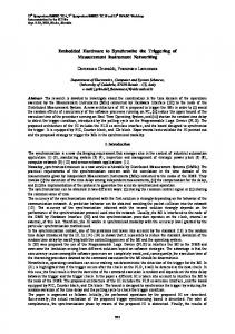
Figure 1: Schematic setup of a balanced optical crosscorrelator and sketched travel of the optical pulses inside the device. See text for details. A more detailed view of the optical setup is given in Fig. 1. After combining both laser beams on a common optical axis the horizontally polarized input pulses enter the cross-correlator through a first dichroic mirror, which is transmissive at 800 nm and 1550 nm, but reflective at the sum frequency of the input pulses. Then the pulses are focussed into the phase-matched sum frequency generating BBO crystal and collimated by a second lens. The resulting sum frequency is transmitted through a second dichroic mirror and passed through an optical bandpass filter onto T23 Timing and Synchronization
Proceedings of EPAC08, Genoa, Italy the first photo detector. Assuming Gaussian-shaped input pulses with the intensities I1 (t) and I2 (t), the measured intensity of the SFG component I + (t) is given by the convolution of the input pulses: I+,I (t)
∝ =
�∞
−∞
I1 (τ )I2 (t − τ ) dτ
� � (t − Δt)2 � .(1) exp − 2(σ12 + σ22 ) 2π(σ12 + σ22 ) 1
The amplitude of this Gaussian is highly sensitive to changes in the relative timing Δt between the input pulses, and by this means the amplitude change is a measure for the timing change. The remaining fundamental pulses are reflected by the second mirror and experience a group delay change by passing a small silica slab (GDD) because of the refractive index difference for the different center wavelength. The now swapped pulses are again focussed into the nonlinear crystal, generating another SFG component I+,II , which is reflected by the first dichroic mirror into the second detector arm, filtered and detected by a second photo detector. With this technique, the measured difference signal I+,I −I+,II at the detector’s output is, in a small region around the zero crossing, proportional to the relative timing between the two input pulses and completely background-free, i. e. if there is no temporal overlap, the signal vanishes. Furthermore, by using this balanced detection scheme, the signal is insensitive to amplitude noise of the laser systems. To keep both laser systems synchronized to each other, the balanced detector’s output signal around the zero crossing will be fed back into an electronic control loop, which stabilizes the repetition rate of the diagnostic laser with a piezo transducer and a motorized delay stage inside the cavity, resulting in a nearly drift-free and temperature independent operation on a long time scale.
Nonlinear Properties of BBO We chose beta barium borate (BBO) as the nonlinear optical element, which is a negative uniaxial crystal with an exceptionally large birefringence (n o > ne , Δn ≈ 0.13) and a low temperature sensitivity of the indices of refraction, resulting in a large phase-matching bandwidth. Another advantage is its high damage threshold, which allows the use of ultra-short pulses with high pulse energies in prototype development and first measurements. The phase-matching angle [5] is calculated to be Θ pm = 22.2 deg based on the Sellmeier equation for the used collinear type-I configuration. For this type of phasematching both input beams have to be collinear ordinary beams inside the crystal while the sum frequency component becomes an extraordinary beam experiencing a large walk-off angle of 54.7 mrad, which additionally can be used to seperate this beam from the background in the detectors. Furthermore, BBO has the highest conversion efficiency in the realized type-I (−) (ooe) configuration. 06 Instrumentation, Controls, Feedback & Operational Aspects
THPC160
FIRST MEASUREMENT RESULTS Currently, there is no end-point of an stabilized fiber link available in the laboratory, so the timing reference is a free running erbium doped-fiber laser generating 200 fs pulses with a repetition rate of f EDFL = 40.625 MHz, which is the 32th harmonic of the 1.2999996 GHz reference frequency of FLASH. As the Ti:sapphire has a repetition rate of 81.25 MHz, we expect the SFG signals to have a rate of 40.625 MHz as the greatest common divisor of the laser repetition rates.
Measurement Principle Fig. 2 shows the planned setup to characterize the optical cross-correlation scheme and to evaluate its long term stability and jitter performance using an out-of-loop analysis with two identically built optical cross-correlators.
Figure 2: Planned experimental setup used for drift measurements. The laser systems can be phase-locked by an RF control loop or by the described optical cross-correlator. A second, identical cross-correlator enables out-of-loop measurements. The reference laser emits 17 mW average mode-locked power, which is distributed to both of the devices through a 50:50 coupler and unstabilized single mode fiber, which leads to approximately 6 mW average power at the input mirrors after passing a quarter and a half waveplate for polarization control (not shown in Fig. 1). A fraction of the Ti:sapphire’s average output power of 460 mW is tapped off by a beam splitter and distributed with another beam splitter to the cross-correlators providing approximately 35 mW and 20 mW at their input mirrors after chirping the pulses from 20 fs to about 100 fs. The Ti:sapphire laser can be phase-locked to the EDFL with an electronic control loop based on a RF phase detector with a timing jitter in the order of 80 fs to initially find temporal overlap inside the nonlinear cystal, thus generating the sum frequency signal. Then the control loop based on the SFG detection as described above can be closed to supersede the RF lock.
Detection of the SFG Difference Signal The temporal overlap of both laser pulses inside the crystal can be achieved by shifting the EDFL phase relative to T23 Timing and Synchronization
3367
THPC160
Proceedings of EPAC08, Genoa, Italy
the one of the Ti:sapphire with a vector modulator incorporated in the RF control loop. Fig. 3 (blue curve) shows the laser pulses after combining on a 10 GHz photo diode measured with a fast oscilloscope. The large peaks repre-
0
0.25 0.2
laser pulses 1st photo detector 2nd photo detector
−0.04
0.15
−0.06
0.1
−0.08
0.05
−0.1
PD voltage (V)
PMT voltage (V)
−0.02
0 0
5
10
15 20 time (ns)
25
30
35
Figure 3: Measured laser pulses on a 10 GHz InGaAs photo diode (blue) and both individual SFG signals (orange, red) at a fixed delay Δt. sent the temporally overlapped pulses with a repetion rate of 40.625 MHz, while the small pulses in between are the not contributing Ti:sapphire pulses due to its repetition rate of 81.25 MHz. By the use of photo multiplier tubes with a short rise time, we can measure the individual SFG signals of both detectors, also shown in Fig. 3 (orange and red curves). The amplitudes of the signals, are nearly equal at this fixed delay Δt between the input pulses, thus being near the zero crossing of the difference signal to lock on. Besides the repetition rate of 40.625 MHz, an asymmetric amplitude change of the SFG signals with varying delay Δt is a strong indication, that the optical setup works in principle. Fig. 4 shows the difference signal (blue squares)
1
measured data Gaussian fitted data slope = 8.723 mV/fs
0.8
ADC voltage (V)
0.6
generated with a low-noise differential amplifier and sampled with an ADC, while scanning the relative timing Δt between the input pulses. The resulting curve, albeit being averaged 10 times at each sample point, shows a good agreement with the expectations. The observed shoulders in the curve at negative times might arise from reflections at the lenses or the crystal surfaces themselves and are to be investigated in more detail. Because of this, we have to fit a sum of five Gaussians to the data (orange curve in Fig. 4), in contrast to the expected difference of only two Gaussians according to eq. (1). From the fit, we extract a slope around the zero crossing of 8.7 mV/fs, which is sufficient for the optical based control loop. The distance between the maximum and the minimum of the difference signal amounts to 280 fs, which is approximately 100 fs or 30% larger than calculated and therefore reducing the value of the slope. Further investigation of this will include careful characterization of all pulse lengths in the setup and changing the group delay glass accordingly.
SUMMARY & OUTLOOK We are developing a new kind of a nearly drift-free, temperature independent, two-color balanced optical crosscorrelator incorporating only one nonlinear crystal [6], which will be used to phase-lock two individual laser systems operating at different center wavelength and different repetition rates, where one has to be a harmonic of the other’s. Recently, we obtained promising results by means of a sufficient slope around the zero crossing of the difference signal. The next step is to close the control loop and make short- as well as long-term stability measurements with an identical out-of-loop cross-correlator. After the installation of an actively length-stabilized fiber link distributing the light pulses in the laboratory, the Ti:sapphire laser can be locked to FLASH’s master laser oscillator, which will allow us to make electro-optic bunch arrival time measurements [7] with higher accuracy as a first key experiment. The same type of optical crosscorrelator can be used for other Ti:sapphire based diagnostics experiments, as well as for the pump-probe laser and even for injector laser stabilization, which presumably only requires another type of nonlinear crystal.
0.4
REFERENCES
0.2 0 −0.2 −0.4 −0.6 −0.8 −1 −1.5
−1
−0.5 0 0.5 relative time Δt (ps)
1
1.5
Figure 4: Measured difference signal by an optical crosscorrelator (blue) and a sum of Gaussian fits to the data (orange) with a slope of 8.7 mV/fs around zero crossing. 06 Instrumentation, Controls, Feedback & Operational Aspects
3368
[1] A. Winter et. al., EPAC’06, Edinburgh, UK, 2006, TUPCH028, p. 1061 [2] J. Kim et. al., FEL’07, Trieste, Italy. 2004, TUAOS03, p. 339 [3] Massimo Altarelli et. al. (editors), “XFEL TDR”, DESY 2006-097, 2007, http://xfel.desy.de/tdr/tdr [4] F. L¨ohl et. al., EPAC’08, Genoa, Italy, 2008, TUPC135 [5] V.G. Dmitriev, G.G. Gurzadyan, D.N. Nikogosyan, “Handbook of Nonlinear Optical Crystals”, 3rd Edition, 1999, Springer [6] T. R. Schibli et. al., Opt. Lett. 28(11):947–949, 2003 [7] V. Arsov et. al., EPAC’08, Genoa, Italy, 2008, THPC152 T23 Timing and Synchronization