cuberille. Therefore, the cuberille is made up of equally spaced voxels. ..... The Marching cubes algorithm decides, at a given cube, whether the surface.
An Overview of Rendering from Volume Data | including Surface and Volume Rendering Jonathan C. Roberts� University of Kent at Canterbury December 1993 Abstract
Volume rendering is a title often ambiguously used in science. One meaning often quoted is: `to render any three volume dimensional data set'; however, within this categorisation \surface rendering" is contained. Surface rendering is a technique for visualising a geometric representation of a surface from a three dimensional volume data set. A more correct de nition of Volume Rendering would only incorporate the direct visualisation of volumes, without the use of intermediate surface geometry representations. Hence we state: `Volume Rendering is the Direct Visualisation of any three dimensional Volume data set; without the use of an intermediate geometric representation for isosurfaces'; `Surface Rendering is the Visualisation of a surface, from a geometric approximation of an isosurface, within a Volume data set'; where an isosurface is a surface formed from a cross connection of data points, within a volume, of equal value or density. This paper is an overview of both Surface Rendering and Volume Rendering techniques. Surface Rendering mainly consists of contouring lines over data points and triangulations between contours. Volume rendering methods consist of ray casting techniques that allow the ray to be cast from the viewing plane into the object and the transparency, opacity and colour calculated for each cell; the rays are often cast until an opaque object is `hit' or the ray exits the volume.
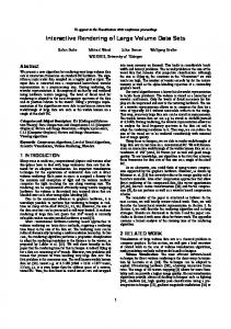
1 Introduction This paper considers the rendering of three-dimensional data { used for the visualisation of datasets. The methods can be grouped into two: (1) Surface rendering and (2) Volume rendering; both formally de ned above. However the datasets can be represented in many coordinate systems. These can be grouped under ve headings: Cartesian, regular, rectilinear, curvilinear and unstructured, as represented in Figure 1. Most of the rendering algorithms we discuss use Cartesian and regular data sets; for more information on rendering and visualising rectilinear and curvilinear data refer to reference [WCAR90]. The three-dimensional Cartesian model is often referred to as the cuberille model. The term cuberille is taken as the three dimension variant of the two dimensional name: \quadrille". Herman and Lui [HL79] describe the quadrille as being two orthogonal sets of parallel lines that are equally spaced; the lines separate the area into squares. A voxel (or volume element) is one part of a cuberille. Therefore, the cuberille is made up of equally spaced voxels. � Sponsored by
a grant from the Science and Engineering Research Council (SERC)
1
Cartesian (i,j,k)
Regular (i+dx,j+dy,k+dz)
Curvilinear
Rectilinear
Unstructured (usually in triangle sections)
Figure 1: Representations of the data-type groups P
Q
Contour Data points
Contour Segment
Figure 2: Structured data points forming a contour
2 Surface Rendering
Early methods of visualising three dimensional data used contoured planes, acting as slices throughout the data, these were usually connected, to produce a surface, using triangle sections. Sections were originally composed by manual quali cation, later this method progressed to a semi automatic and nally an automatic decision function. The original idea of the contours came from the manual drawing of contours on acetates; these acetates were stacked on top of each other with spacers between them, from this a feeling of the overall volume could be achieved.
2.1 Finding the (contoured) surface
There are two main data representations, for contoured surfaces (1) a structured planar representation, where the data points can be sorted into planes, Figure 2, contours can then be easily created and (2) unstructured random data points | where the points are in a random order, Figure 3. A surface can be made, over a set of arbitrary spaced points, from a series of triangulations. These points can be connected, by triangles, in many ways, however, there are some general algorithms to solve this problem, these are brie y listed below, usually these algorithms add constraints to the data points one such constraint is for sets of points to `lie' within planes, this speci cation is discussed in greater detail. 2
Figure 3: Unstructured data points, with a corresponding contour 1. A recursive triangular subdivision method can be used to subdivide the unstructured data into triangles. This continues until a pre-de ned limit is reached. 2. A convex hull can be shrunk over the surface to nd the outer points, these points can then be triangulated to form a surface.
2.2 Surface Rendering from Planar Contours
Planar contours are contours on a particular plane. Throughout this text we shall use contours to mean one closed loop of `contour segments' on a particular plane, where a `contour segment' is a straight line between two data points and the planes are perpendicular to each other; Figure 2. Two adjacent contours are de ned as P0; P1; P2 : : :Pm?1 , followed again by P0 and likewise for Q: Q0; Q1; Q2 : : :Qn?1 hence the contour P and Q are modulo n and m respectively. Figure 4. There are two main problems when producing a surface form a structured planar contoured data set. These are (1) the correspondence problem and (2) the Tiling problem.
The Correspondence Problem This problem occurs when a contour segment on one plane is being created and there are two or more closed contours on the plane; the problem is \how to produce a contour given a set of points in particular plane". Some solutions to this problem are given by Meyers et al. [MSS92]. His rst solution uses elliptical cylinders; that produce contours tted with ellipses; his second solution uses a cost spanning tree that links the contours together in adjacent sections, a graph is used to nd the best connection for the contours. The Tiling Problem This problem describes the problem of \how to join triangle sections (tiles) together, between the contours, to produce a surface". Some, solutions to the tiling problem are explained below. A tile is de ned as three points, `two from the P plane and one from Q' or `one from the P plane and two from Q'; this is written as (Pi ; Pk; Qj ) or (Qi; Qk ; Pj ). The problem is to decide the orientation of the next tile, Figure 4, whether the next tile is C1 or C2. Fuchs [FKU77] strictly speci es the triangle segment, which he nicknames a \tile" with the following two rules: 1. Each contour segment will be used for exactly one tile. 3
P
m-1
Pj+1
Pj C2
A Q
n-1
B
C1 Qi+1 Qi
Right span for tile A (left span for tile B)
Figure 4: Two Parallel contours
Figure 5: Toroidal Representation 2. A left span of a particular tile will be also used as the right span of another tile, and vis�e versa.
2.2.1 Graph theory
Fuchs [FKU77] solves the problem `to decide the orientation of the next tile', using graph theory, stating: \All acceptable surfaces de ned between two contours can be associated with certain cycles in a directed toroidal graph", see Figures 5 and 6. An optimum surface (as described by [FKU77]) corresponds to a `minimum cost acceptable trail' in the toroidal graph. The cost of a trail is the \sum of the arcs traversed by it". The problem of nding the lowest cost path can be studied by referring to [Joh77] or [Har69]. Examples of corresponding graphs and contour parts can be seen in Figures 7 and 8.
2.2.2 Heuristic Methods
The tiling problem can be expressed as a cycle in a directed graph so the solution can be described by an heuristic function. These describe a path that is a \good" approximation to the best solution. The word path, in this context, is used to mean a closed set of traversals from the rst through the last vertex to the rst 4
Figure 6: Directed graph of the toroidal representation
0
1
2
3
4
n-1
5
1 2 3 4 5
m-1
Figure 7: Directed Graph for a contour segment
0
5 1
4 3
2
5 0
4 1
2
3
Figure 8: A part of the triangulated contour from the directed graph 5
vertex; that is, from Vertex V00 to Vnm to V00. The major heuristic methods are described below. Keppel (as described by [GD82]) applies tetrahedron to the points and computes the volume of the tetrahedron at a given vertex point (Vij ). If the vertical tetrahedron volume is larger than the horizontal then the next vertex Vi;j +1 is considered; otherwise the arc is marked and the vertex Vi+1;j is considered. The tetrahedra are formed by using extra points: Op or Oq which are interior to the contours. The calculation must be performed on a series of convex or concave parts | therefore, a lot of pre-processing is required. The Corresponding equations for the vertical and horizontal tetrahedra volumes are shown in equations 1 and 2 respectively. For more information refer to [GD82]. v fPj Qi Qi+1 Opg Ti;j
(1)
h fPj Qj +1Qi Oq g Ti;j
(2) Fuchs [FKU77] describes a method using the area of the tiles. The smallest area is chosen. This works best with a normalisation to the unit square at the origin. Christianson [CS78] describes a heuristic using the length of a span as the appropriate heuristic weight, the span can either be the left or the right span, de ned on Figure 4. The smaller span is chosen. Christianson's heuristic, as stated by Ganapathy [GD82] works best on contour pairs that are \coherent in shape and mutually centered", the centering and coherency can be achieved by a normalisation from a transformation to the unit square at the origin. Ganapathy's heuristic determines the next contour by considering the cumulative addition of previous weights and the new possible weights. A weight of a contour tile is de ned as the circumference of a normalised tile divided into the length of the contour segment. The next contour can either be the vertical or horizontal contour, both the horizontal and vertical weights are accumulated into two separate running scores and the decision regarding the next tile is taken so that, in an optimum triangulated surface, the di�erence between these scores is minimised. For an optimum surface the di�erence between these scores is zero. Therefore, this produces a good approximate to the optimum triangulated surface.
2.3 Surface Rendering in Cuberille Space
Another method of surface rendering uses the cuberille model. In the Cuberille Space the data points can be thought of as values with a surrounding cube or voxel (volume element). The image surface is created from a group of shaded voxel surfaces. The voxels representing the object can be formed by thresholding the data-space, each voxel is therefore either inside the required object threshold or outside the threshold. Therefore, a piece of the surface is created at the boundary of an inside voxel and an outside voxel. This, however, does produce a blocky image; but can be ltered and smoothed in the image space. Figure 9 shows an example of an object represented by boundary pieces in cuberille space. Artzy, Freider and Herman [AFH81] create a list of all the voxels inside the object (by thresholding the data) then, by a breadth rst search (on connectivity { from a directed graph) they create a connected component for the surface that they render using a Z{bu�er technique. This technique requires an initial seed position on the surface. 6
Figure 9: An Object in Cuberille Space Herman and Liu [HL79] use the cuberille environment, and the speci cation of the data being square and the voxels lying in the same plane, to their advantage. Stating if the centre of a voxel face � is behind another centre face ; then completely hides �. This simple phenomenon breaks down when non-square elements are used. Herman and Liu also use the Z{bu�er algorithm, to nd the visible surface and the Warnock algorithm for shading. Their image space smoothing algorithm uses weighted values on the eight boundary neighbouring pixels; they claim that the whole method was faster than surfaces that are \composed of triangles at arbitrary orientations; their display requires greater amount of computer processing than the display of surfaces which are composed of squares at restricted orientations". Gordon and Reynolds [GR85] and also Chen, Reynolds et al. [CRHK85] discuss other shading methods within the cuberille model; these include: distance only shading, gradient shading and constant shading.
2.4 Isosurface | Threshold Methods
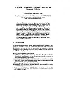
As the data can be represented by a series of voxels surrounding each data point, so the data can be represented as being the vertices of a voxel. In this representation a surface cuts through the voxel. The orientation of the surface can be estimated by the in and out nature of the 8 vertices. Lorensen et al. [LC87] created a large major case lookup table to de ne how a surface cuts through a given cube, from vertex information and termed this method the \Marching Cubes" algorithm. As with the cuberille approach the data is thresholded. Either this threshold is incorporated into the algorithm (as in the Marching Cubes [LC87]) or the whole data set can be pre-processed and the relevant data extracted [VMW83]. Vannier et al. [VMW83] use a pre-processing method on Computed (Axial) Tomography (CT) scans for \... Cranofacial Surgical Planning and Evaluation". CT scans are formed from a computer comparing the absorption of X-rays through di�erent planes of a patients body. Di�erent materials in a body 7
absorb di�ering amounts of X-rays. Vannier divides each of the individual slices into separate les; these les are ltered through the threshold value. The processed threshold data is saved to le in the same CT format. The les can be read by imaging technology designed for CT scans. Vannier uses contours and an interactive CAD system to produce life-size displays that can be measured and altered by surgeons | therefore, aiding the surgeons in their calculations for operations. Contouring over CT scans is relatively simple, because the scans are, by nature of the scanning device, planar. Marching cubes is an algorithm that calculates surfaces that are of equal density | an isosurface. There are two stages to the algorithm: 1. to nd the surface that is required by the user. This is speci ed by a threshold value. Corresponding triangles are then created and joined to make a `surface'. 2. the second stage calculates the normals at the vertex of each of the triangles. These are then used to produce Gouraud shaded objects. The algorithm determines the surface by deciding how the surface intersects a given cube. Lorensen and Cline [LC87] have worked out that a surface can intersect a cube in 256 (28 ) ways | this can be broken down into 14 cases if topology and rotational symmetry are considered, Figure 10. The whole 256 ways are stored in a `cube table'. The Marching cubes algorithm decides, at a given cube, whether the surface intersects that cube. If no intersection occurs the cube is either totally outside the surface, or totally within the surface and case zero is assigned. If there is an intersection one of the 256 cubes is assigned to that particular voxel. The next cube is `marched' upon. The eight densities, at the vertices of a cube, are ltered to the threshold value and are used as an index into the `cube table'. The exact positions, of the intersections, of the surface pieces are found by linear interpolation of the densities. The nal preparation stage calculates a normal at each triangle vertex. The triangulated surfaces are rendered by an appropriate renderer. The \Marching Cubes" algorithm uses a lookup table of 256 values, however, this table is created from the \major surface cases", there are many ways of placing a surface through a cube governed by the vertices. The major cases can create features in the rendered image that were not in the original and vis�e versa. These features are produced by the ambiguities that are inherently present when placing a surface through an object (a cube) and using only vertex (neighbour) information. The worst case is the ambiguity caused by the parallel case, Figure 11. The major case lookup table (from Lorensen) describes the correct con guration in Figure 11 to be case A, however this need not always be the correct case. Wilhelms and Gelder ( [WG90]) discuss some of the methods for disambiguating the \major case | lookup table". An ambiguous face, is a face that contains a possible ambiguous representation { Figure 11. These methods include: 1. Facial Average | the values at the corners of the cube are averaged for the ambiguous face and then this value is used to disambiguate the case. 2. Gradient methods | Center pointing gradient { a gradient value, of neighbouring points (outside the cube) are calculated. These values are used to `o�set' the actual density values and these new values are used to calculate (and therefore, disambiguate) the center point of the ambiguous face. 8
Figure 10: The fourteen main cube cases
A
B
C
Figure 11: The worst ambiguity from the \major case" lookup table 9
The Middle tetrahedra
Figure 12: The Tetrahedra orientation within a cube
Figure 13: The triangles for a given tetrahedra 3. Gradient methods | quadratic t { The underlying gradient function is represented by a quadratic curve, whose zero points are used to estimate the sign at the ambiguous point { to choose the correct topology. This method only works well if the underlying gradient function can be represented by a quadratic curve. One slight variation on the \Marching cubes" algorithm can be implemented when the data points become very close together; when this happens the triangles become very small; therefore, the triangles can be replaced by spheres or eventually pixels. This method has been named \dividing cubes". Another threshold method, can be formed by extending the \marching cubes" algorithm to use tetrahedra; hence, \Marching Tetrahedra". The usual con guration uses ve tetrahedra that t exactly within a cube. The advantage of using this topology is that a ner detailed surface is created, however ambiguities are still present { because the isosurface is created by considering only neighbour data points. Figure 12. The orientation of each of the triangular parts for given tetrahedra is shown in Figure 13.
10
3 Volume Rendering Volume Rendering, as stated before, uses no geometric representations of the data and usually considers all the voxels in an object for the display of one view. As Bob Drebin stated \.. volumetric data should not be skimmed to yield only surface renderings" [Fre89], however, renderings of this form (even with todays technology) tend to be produced at a slower speed than surface type renderings | although a much higher quality image is produced. When viewing volume rendered images the user must remember that the drawing has been created from sampled `fuzzy' data; Surface renderings produce `crisp' images from `fuzzy' datasets, this phenomenon can lead to misinterpretations of the rendered image; Volume renderings, with transparency, can create the `fuzzy' images. There are two main subsections to Volume Rendering (1) Backward projection methods | ray casting techniques (an image space method) and (2) Forward projection methods (an object space method). This text assumes the reader understands the basics of ray tracing or ray casting techniques; for more information refer to [WW92, FvDFJ90]. Ray tracing follows each ray from the image plane through the model space to nd the contribution of the model to a particular pixel. The projection method is the opposite of ray tracing { tracing the model to the image plane; each point is accumulated at the current pixel point. The projection methods can be achieved in either \front-to-back" or \back-to-front" order. With surface based methods, as described above, some form of threshold value is used to create an approximation of a surface; the threshold method often creates extra spurious surface parts, not in the original; or misses parts (holes) in the surface, that were in the original model. These are known as false negatives and false positives. This phenomenon can be overcome, to a certain extent, by using Volume Rendering Techniques.
3.1 Backward Projection | From Clouds to Volume Rendering
From browsing the literature, it can easily be seen that Blinn's cloud model [Bli82] for ray tracing particles in clouds sparked o� a growth of ray tracing literature for Volume rendering. Blinn's cloud model used a volume (of width T) lled with particles representing a cloud. The brightness of the cloud depended upon the amount of particles that are `lit' by the rays of light; as the particles are small they are not individually seen. Blinn states four main participants in the calculation. 1. Phase functions (based on the phase angle) that is the value of the brightness of a particular particle depending on the viewing angle. 2. Albedo | this is the proportion of re ected light corresponding to the amount of light hitting the particle 3. Scattering | each particle will only be seen if there are no other particles in the line of sight, of either the incoming or outgoing ray of light. 4. Transparency | this is the amount of light that manages to penetrate the clouded volume without being re ected o� any particles. This is the amount of light that can be seen through the image.
11
RGB or Opacity
Figure 14: Examples of possible transfer functions
3.2 Backward Projection | Ray tracing including Opacity
Mark Levoy [Lev88] discusses a method to produce surfaces from volume data using a ray tracing technique. His method is split into several stages so processing, after alterations, can be kept to a minimum. He also uses look-up table for the opacity and transparency values. There are two basic pre-processing phases: 1. The data array is used as the input to the shading model. A colour is associated with each data point and the Phong Shading method is used. The shading stage produces another array of \voxel colours". 2. The opacities of the data set (from the original array) are found. The opacity value can be assigned in one of many ways, to produce an isosurface at a given intensity: a. by using a single, simple, threshold density. b. using a window threshold. however, both these methods can produce results that have missing surface patches and/or additional surface patches that are not contained within the original data. A better method is: c. to assign a variable opacity value to the voxels. The voxels in the array with the required colour are given the maximum opacity and the remainder are assigned a value of opacity depending on the closeness of the actual colour value inversely proportional to the local gradient vector. The variable opacity values allow, by accumulating the opacities, more than one isosurface to be displayed in one picture. After the pre-processing steps the rays are cast into these two arrays. The rays are sampled at even spaces along the arrays and tri-linear interpolation is used to compare the opacity and colour values at the regular points. The compositing phase acts in a back-to-front order. Within CT scans the data can be imagined as layers from an onion | the skin layer followed by a liquid layer followed by a bone layer, | each material can be assigned an exact opacity value and the intermediate layers can be de ned intermediate values. Also, if the bone layer is the only required viewing layer then this surface can be allocated a high opacity value. Levoy, also proposes ways of increasing the image quality, he achieves this by supersampling | interpolating the data points to create intermediate points, this reduces the aliasing artifacts, but increases computational expenses. Upson and Keeler [UK88] present a ray casting method (and a projection method); here they use transfer functions to map opacity values to the relevant density values; this relationship may be smooth or discontinuous, Figure 14. 12
Each ray is cast into the volume, as the \visible volume detector". At regular intervals, along the path, a scalar value is calculated by tri-linearly interpolating the eight nearest values; this re-sampling method is similar to Levoy's method [Lev88]. This new scalar value, at each discrete point, is used with the appropriate transfer function to calculate the transparency/opacity, colour, shading and texture at that point; the values are integrated as the volume is traced. The key to this work is to treat the original data as `nondiscrete data', and tri-linearly interpolating neighbouring data points. When the required opacity is exceeded the exact position of the maximum opacity value is calculated and the next ray is cast into the volume. A variation on this general ray casting theme is presented by Sabella [Sab88]. Here, Sabella uses a Density Emitter which is a function that he states: \models the density of particles, not the particles themselves", and \can be regarded as a continuous function". This idea is similar to Blinn's method [Bli82]. The intensity of the light reaching the eye, in Sabella's method, allows varying densities where as Blinn's method is xed. The Brightness equation is listed in equation 3. He states, the density �(x; y; z ) emits an energy of C� and absorbs an energy of �� per unit length. A diagram of an example volume, with one ray cast and the peak values encountered along the ray are shown in Figure 15. Brightness = �(x; y; z ) �(x(t); y(t); z (t)) �(t)
M
where:
t1 : : :t2
D C
e
?�
Rt
�
� (�)�� t1
Z
t2 ?� R t � (�)�� � (t)�t e t1
t1
(3)
Density eld. Parameterised density eld. Short-hand of, above, density eld. Parameter to control density spread. Maximum, | Peak value encountered along ray. Start and end voxel on the path of the ray. Distance, at which the peak value is encountered. Center of gravity. Parameter value to adjust the rate of attenuation. Attenuation along the ray due to the density eld.
3.3 Forward Projection methods
Upson and Keeler [UK88] also describe a forward projection that they named the cell-by-cell method. This is similar to the ray casting method in that the opacity, colour and shading values are calculated from the transfer functions and the scalar values, but the \visible volume detector" is based on a projection or scan line method. This technique is similar to the Z{bu�er algorithm. Each cell is scanned completely before moving onto the next cell. Many scan lines are applied to a single cell; on a particular scan line an intersection polygon is created; this is broken down into smaller polygons (called spans { when projected onto the image plane), intergration is used (from tri-linear interpolated values) to nd the average contribution to each pixel in each scan line. The correct colour opacity is calculated and after a whole cell has been processed the next cell is scanned. The method progressively displays the view on the screen | the front most pixels are displayed rst followed by the more distant pixels in each plane. Shirley and Tuchman [ST93] discuss a similar method to the cell-by-cell method. They use a method that transforms all the data into tetrahedra pieces; each tetrahedra piece is allocated a transparency and colour value depending on 13
p (t) M
t2
Centre of Gravity
t1
ne
ng wi
Pla
e
Vi
Figure 15: Histogram of densities along a ray-traced path the position and distance from the viewer. The pieces are then scan converted using a painters algorithm. Another projection method is described by Drebin et al. [DCH88] { here they transform the volume data so the `rays' can be projected into the volume and onto the image plane, by using a scan line method. This can be achieved at any angle by using a sequence of four transformations, using the Euler angles: �; �; . T = Pz Ze Rz ( )Ry (�)Rz (�) (4) T transform P transformation Where: Rz Perspective z rotation about Z axis Ry rotation about y axis Drebin uses a two pass image transformation method and mentions a possibility of generalising this two pass transformation into a three pass image transformation, this would reduce the amount of resampling stages. A Three Pass image transformation method (based on Drebin's proposal) is explained by Hanrahan [Han90]. Hanrahan claims, referring to the two pass techniques in Drebin [DCH88] that the three pass transformations are \more e�cient in time and produce higher quality results for general views than the techniques proposed in Drebin et al." Drebin also uses a classi cation model that operates on any volume made up of a mixture of substances. This calculates the percentage of a particular material in the voxel, from this the colour value for a particular voxel can be found. Boundaries can be detected by the change in density | a probabilistic method is used, taking into consideration the number of materials present in the whole volume and the percentage of a material in a voxel, to disambiguate the exact boundaries. A typical material assignment, from Drebin, is shown in Figure 16.
14
100%
air
fat
soft tissue
bone
0% CT number
Figure 16: Examples of possible transfer functions
4 Summary
We have discussed here then main techniques for Rendering Volume data; we acknowledge this as not being a comprehensive overview. There are some techniques known as Hybrid Volume Rendering Techniques [Lev90], [RK92], [vWHVP92]; that allow polygon and volume data to be visualised in one image; that haven't been discussed and are useful for displaying a scale or grid (or other polygon de ned objects) over, behind and through the volume data. Below is a brief review of the main methods discussed. Surface Rendering methods include: 1. Placing tile pieces between contours require a decision method, to nd the next tile orientation, including: (a) graph theory [FKU77]. (b) functions [Joh77] [Har69] [GD82] [CS78]. 2. Isosurface (Threshold Methods) (a) Marching Cubes { which uses a binary threshold on the vertices of a cube, and a look up table, to decide on the orientation of the surface through that voxel [LC87]. (b) Marching Tetrahedra { similar to the Marching Cubes algorithm but the cubes are broken into ve tetrahedra. (c) Dividing Cubes { where the cube topology is transferred into points instead of triangles. Volume Rendering Methods include: 1. Backward Projection methods { Ray Casting Ray Tracing including opacity [UK88] [Lev88] [Sab88] [Bli82] 2. Forward Projection methods (a) Cell-by-Cell method { scan the cells like a Z-bu�er algorithm [UK88]. (b) Volume Transformation { transform the volume so the voxels are perpendicular to the viewing angle - then scan the cells [Han90] [DCH88]
5 Conclusion From reading manuscripts, there seems to be a distinct argument between Surface Rendering and Volume Rendering techniques; that one produces false positives and negatives and the measurements cannot be taken from the other. We 15
propose that neither one technique is overall better { they both have major disadvantages and advantages { so di�erent techniques should be used for the visualisation of a data set. With Surface Rendering (and Volume Rendering at an isosurface) exact measurements are possible; with these methods an overall understanding of the image is di�cult to grasp; however, with a transparent Volume Rendered image an overview of the data can be easily grasped. Surface rendered images take less time to compute than Volume Rendered images however the image quality is usually greater in Volume rendered images. Quality verses production time is a usual comparison and with certain visualisations (especially medical), a lower quality image could cause mis-interpretation of the data which could be very severe. To aid disambiguity of the object, interaction should be available; including viewing from di�erent angles, cutting planes and exploring the image in real time. The author suggests that both Volume and Surface Rendering techniques should be coincidentally used: Volume Rendering to create an overall impression of the three-dimensional view and Surface rendering for an `exact view' at a particular isosurface.
References [AFH81]
E. Artzy, G. Frieder, and G. T. Herman. The theory design, implementation and evaluation of a three-dimensional surface detection algorithm. Computer Graphics and Image Processing, 15:1{24, 1981. [Bli82] J.F. Blinn. Light re ection functions for simulation of clouds and dusty surfaces. IEEE Computer Graphics '82 Proceedings, 16(3):21{29, 1982. [CRHK85] L.S. Chen, R.A. Reynolds, G.T. Herman, and J.K. Kdupa. Surface shading in the cuberille environment. IEEE Computer Graphics and Applications, 5(12):33{43, December 1985. [CS78] H.N. Christianson and T.W. Sederberg. Conversion of complex contour line de nitions into polygonal element mosaics. Computer Graphics SIGGRAPH Proceedings, 12:187{192, 1978. [DCH88] R.A. Drebin, L. Carpenter, and P. Hanrahan. Volume rendering. Computer Graphics, 22(4):65{74, 1988. [FKU77] H. Fuchs, Z.M. Kedmen, and S.P. Uselton. Optimal surface reconstruction for planar contours. CACM, 12(3):69{75, 1977. [Fre89] K.A. Frenekl. Volume rendering. Communications of the ACM, 32(4):426{435, 1989. [FvDFJ90] J. Foley, A. van Dam, S. Feiner, and Hughes J. Computer Graphics | Principles and Practice (Second Edition). Addison-Wesley Systems Programming Series, 1990. [GD82] S. Ganapathy and T.G. Dennehy. A new general triangulation method for planar contours. Computer Graphics SIGGRAPH Proceedings, 16:69{75, 1982.
16
[GR85] [Han90] [Har69] [HL79] [Joh77] [LC87] [Lev88] [Lev90] [MSS92] [RK92]
D Gordon and R.A. Reynolds. Image space shading of 3dimensional objects. Computer Graphics and Image Processing, 29(3):361{376, March 1985. P. Hanraham. Three-pass a�ne transformations for volume rendering. Computer Graphics, 24(5):71{76, 1990. F Harary. Graph Theory. Addison-Wesley, 1969. G.T. Herman and H.K. Liu. Three-dimensional display of human organs from computed tomograms. IEEE, Computer Graphics and Applications, 9(1):1{21, 1979. Johnson. E�cient algorithms for shortest paths in sparse networks. ACM, 24(1):1{13, January 1977. E.W. Lorensen and H.E. Cline. Marching cubes: A high resolution 3d surface construction algorithm. ACM Computer Graphics, 21(4):163{169, 1987. M. Levoy. Volume rendering { visible volume rendering. Computer Graphics and Applications, 8(3):29{37, 1988. M. Levoy. Volume rendering { a hybrid ray tracer for rendering polygon and volume data. IEEE Computer Graphics and Applications, (3):33{40, 1990. D. Meyers, S. Skinner, and K. Sloan. Surfaces from contours. ACM transactions on Graphics, 11(3):228{258, 1992. K. Roang and M. Kanagasabai. Four methods for the combined visualisation of volume data and geometric objects. Book: \Advances in Scienti c Visualisation" Springer-Verlag; Eds. Post,F.H and Hin,A.J.S, pages 97{104, 1992.
[Sab88]
P. Sabella. A rendering algorithm for visualizing 3-d scalor elds. Computer Graphics, 22(4):51{58, 1988. [ST93] S. Shirley and A. Tuchman. A polygonal approximation to direct scalor volume rendering. Computer Graphics, 24(5):63{70, 1993. [UK88] C. Upson and M. Keeler. V-bu�er | visible volume rendering. Computer Graphics, 22(4):59{64, 1988. [VMW83] M.W. Vannier, F.L. Marsh, and J.O. Warren. Three dimensional computer graphics for craniofacial surgical planning and evaluation. Computer Graphics SIGGRAPH Proceedings, 17(3):263{273, 1983. [vWHVP92] T. van Walsum, A.J.S Hin, J. Versloot, and F.H Post. E�cient hybrid rendering of volume data and polygons. Book: \Advances in Scienti c Visualisation" Springer-Verlag; Eds. Post,F.H and Hin,A.J.S, pages 83{96, 1992.
[WCAR90] J. Wilhelms, J. Challinger, N. Alper, and S. Ramamoorthy. Direct volume rendering of curvilinear volumes. Computer Graphics, 24(5):41{47, 1990. 17
[WG90] [WW92]
J. Wilhelms and A. Van. Gelder. Topological considerations in isosurface generation | extended abstract. Computer Graphics, 24(5):79{86, 1990. A. Watt and M. Watt. Advanced Animation and Rendering Techniques | Theory and Practice. Addison-Wesley, 1992.
18