This full text paper was peer reviewed at the direction of IEEE Communications Society subject matter experts for publication in the ICC 2008 proceedings.
Anchor Node Based Virtual Modeling of Holes in Wireless Sensor Networks Fucai Yu, Younghwan Choi, Soochang Park, Euisin Lee, Ye Tian, Minsuk Jin, and Sang-Ha Kim* Dept. of Computer Engineering Chungnam National University, 220 Gung-dong, Yuseong-gu, Daejeon, 305-764, Republic of Korea {yufc, yhchoi, winter, eslee, tianye, badamul}@cclab.cnu.ac.kr and
[email protected] Abstract—Geographic routing has been addressed in many literatures of ad hoc sensor networks due to its efficiency and scalability. Void areas (holes) bring Geographic routing several problems such as excessive energy consumption and data congestion of hole boundary nodes. Holes are hardly avoided in wireless sensor networks because of various actual geographical environments, e.g., puddles, buildings or obstacles, or uneven energy consumption, even physical destruction. To bypass holes, most existing geographic routing protocols tend to route data packets along the boundaries of holes by perimeter routing scheme. This scheme consumes more energy of the nodes on the boundaries of holes, thus possibly enlarging the holes, we call this hole diffusion problem. In this paper, we propose Anchor Node Based Virtual Modeling of Holes in Wireless Sensor Networks to solve the hole problems faced by geographic routing in wireless sensor networks. Simulation results show that the proposed protocol is superior to other protocols in terms of packet deliver ratio, control overhead, average delivery delay, and energy consumption. Keywords- wireless sensor networks; geographic routing; hole problem; modeling
I. INTRODUCTION Geographic routing [1] algorithms is attractive especially for scalability, as it is possible to scale the network size without increasing the signaling overhead, because routing decisions are inherently localized. In geographic routing scheme, it is assumed that each node knows its own location and the location of its 1-hop neighbors, source node knows the location of the destination and encapsulates the destination location in each data packet, a node sends data packets to an one-hop neighbor which is closest to the destination. This mechanism can minimize the hops from the source to the destination. However, hole diffusion problem may arise due to energy exhaustion of the hole boundary nodes. The nodes located on the boundaries of holes may suffer from excessive energy consumption since the geographic routing tend to deliver data packets alone the hole boundaries by perimeter routing if to bypass the hole. This perimeter routing scheme makes the nodes located on boundaries of holes a higher probability to be used for data delivery than other general nodes. Then the hole may be enlarged due to excessive energy consumption of the hole boundary nodes. We call this as hole diffusion problem. In addition, data congestions may occur in
the hole boundary nodes if multiple communication sessions are bypassing a hole simultaneously. The bigger the hole is, the serious the problems become. In addition, geographic routing fails if there is no neighbor that is closer to the destination than the current node, this is well known as the local minimum problem[2]. The perimeter routing[1][2][3] scheme can solve this problem but lead to excessive energy consumption and data congestions in hole edge nodes. Fig.1 shows a scenario in which source node S sends a data packet to destination node D crossing a hole area by geographic routing mechanism. To facilitate discussion, all general sensor nodes are not drawn out in Fig.1. Dashed line ① indicates the data forwarding direction. When the data packet reaches node I which is on the hole boundary, the local minimum problem arises because no 1-hop neighbor of node I is closer to the destination node D than itself (node I is called a stuck node [2]). By perimeter routing proposed in [1], the data packet will be forward along the boundary of the hole as indicated by dotted curve ②. It is obvious that the dotted curve ② is the shortest path from I to D, but that combined with the path SI , the total length may not be the shortest path from S to D. In addition, if multiple communication sessions are bypassing the hole simultaneously, the probability is very high that the nodes on the boundary of the hole are shared by several communication sessions. Thus data congestions may occur in these nodes. Also, the battery of these nodes will be exhausted faster than that of other nodes in the network, thus possibly enlarging the hole. This is undesired in sensor networks. Dashed zigzag line ③ in Fig.1 shows a more reasonable path from S to D. If the source is aware of the hole, to bypass the hole, the source can select an anchor point V beside the hole, and the data packets are forwarded to point V and then forwarded to D. This path has some advantages: First, this is a shorter path than previous works [1][2][3] if node V are properly selected. Second, since the path are outside of the hole, so no route rediscovery process is needed, thus reduce the overhead incurred in [4][5], the local minimum problem also can be avoided. Third, this path is not along the boundary of the hole, excessive battery consumption and data congestions in these nodes can be significantly reduced. The
*Sang-Ha Kim is corresponding author with the Department of Computer Engineering, Chungnam National University (email:
[email protected]).
978-1-4244-2075-9/08/$25.00 ©2008 IEEE
This full text paper was peer reviewed at the direction of IEEE Communications Society subject matter experts for publication in the ICC 2008 proceedings.
S
③
M
② B0
V
B1
B2 B3
C
C
Bn
r
I
N
Hole
(1)
(2)
(3)
Figure 2. Virtual holes geometric model processes ①
D Figure 1. Scenario of holes problem in sensor network
issue is that how can the source know hole information and how to locate a proper anchor point V so that the path is the most efficient. In this paper, we propose a Anchor Node Based Virtual Modeling of Holes to solve hole problems faced by geographic routing in sensor networks. Firstly, a virtual circle which can exactly cover a hole is geometrically initiated. This virtual circle information is disseminated to all hole boundary nodes. When a hole boundary node received a data packet sent by geographic routing, it sends a Hole Announcement message (HA), which contains the information of the virtual circle, to the source to announce that there is a hole on the data delivery path. Then the source node calculates the location of anchor point according to its own location, the destination location and the virtual circle information. Thereafter, the source sends data packet to the anchor point directly, when the node located on the anchor point receives the data packet, it forwards the data packet to the original destination by geographic routing. The rest of this paper is organized as follows: Section Ⅱ describes how to model a hole with a virtual circle. The routing scheme under in the proposed protocol is given in section Ⅲ. Detailed analysis of the Anchor Node Based Virtual Modeling of Holes scheme is given in section Ⅳ. Section Ⅴ and Ⅵ evaluate the performance and conclude the paper. II.
ANCHOR NODE BASED VIRTUAL MODELING OF HOLES
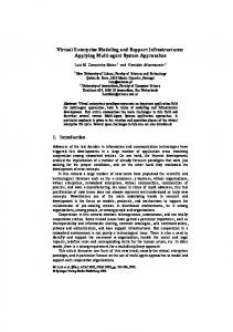
In this paper, we assume that each node knows its own location information and that of all its 1-hop neighbors. Sources and destinations can move but all other sensor nodes are fixed. Source knows the location of the destination, and marks each packet with their destination’s location. Fig.2 shows our hole virtual circle modeling processes. A node can detect whether it is locating on the boundary of a hole by the mechanism proposed in [2]. The node which firstly detects a hole sends out a Hole Boundary Detection (HBD) packet around the hole by the well-known right hand rule[6] (which states that it is possible to visit every wall in a maze by keeping your right hand on the wall while walking forward). The mission of HBD packet is to trace the location information of all nodes on the boundary of the hole. We suppose that nodes B0, B1…Bn with the coordinates (x0,y0), (x1,y1)…(xn,yn)
are on the boundary of the hole. As shown in Fig.2-1, node B0 first detects the hole and initiates a HBD packet marked with its own ID and forwards the HBD packet to the neighbor hole boundary node B1 by the right hand rule. Node B1 inserts its own location coordinate into the received HBD packet and then forwards it to node B2 by the right hand rule. This process continues until the HBD packet has traveled around the hole and eventually been received by the initiator node B0. Node B0 gets the location coordinate of all nodes on the boundary of the hole from the received HBD packet. Then node B0 locates two point P and Q in the network with coordinates: P{(xp,yp)| xp=max{x0,x1…xn}, yp= max{y0,y1…yn}}, (1) Q{(xq,yq)| xq=min{x0,x1…xn}, yq = min{y0,y1…yn}}, As shown in Fig.2-2. C is the centre point of line PQ with the coordinate: C{(xc,yc) | xc=(xp+xq)/2, yc=(yp+yq)/2}, 2
(2) 2
2
Then node B0 calculates a virtual circle (x-xc) +(y-yc) =r with C as the centre and r as radius as shown in Fig.2-3, where r is the longest distance between C and all hole boundary nodes {B0, B1…Bn}, i.e., r=max{ B0C , B1C … BnC }. Here we can see that this circle can cover the hole exactly. Then node B0 initiates a Circle Distribution (CD) packet which includes the coordinate of circle centre C and circle radius r, and sends the CD packet to all hole boundary nodes by the right hand rule again. Then all hole boundary nodes are aware of the centre and radius of the virtual circle. III.
DATA DELIVERY UNDER HOLE GEOMETRIC MODELING
Section Ⅱ described how to model a hole with a virtual circle which can cover the hole exactly. The information of the virtual circle is used for the calculation of the anchor location. This section presents the data delivery processes under this modeling. As shown in Fig.3 where only the hole, virtual circle, and data delivery paths are drawn out, all sensor nodes are ignored. Source node S initiates data packets and forwards them to destination node D by geographic routing. Each data packet header includes an anchor location field, and a flag field indicating whether the packet is straightforward mode or detour mode. The first data packet is initially set to straightforward mode and it anchor location field is set to void by the source. Source also includes the geographic location of the destination in each data packets. The destination location field is only set by source, and left unchanged as the packet is forwarded through the network.
This full text paper was peer reviewed at the direction of IEEE Communications Society subject matter experts for publication in the ICC 2008 proceedings.
y − ys x − xs = (5) yk1 − ys xk1 − xs By the same process described above, source node can get the location of tangent point K2, i.e., (xk2,yk2), and the function of line DV as:
S
U
D`
Hole
C
y − yd x − xd (6) = yk 2 − yd xk 2 − xd Where (xd,yd) is the coordinate of the destination D and is known by source. Then the coordinate of anchor point V, i.e., (xv,yv) can be calculated by (5) and (6).
K1
r r
V K2
D Figure 3. Routing scheme with the hole modeling
In Fig.3-1, source node S sends a data packet to destination D along line SD by geographic routing. When a node locating on the boundary of the hole receives the data packet, e.g., node U, it initiates and sends a Hole Announcement message (HA) to the source node S to announce that there is hole on the geographic routing path. This HA message contains the information of the virtual hole modeling circle, i.e., the center location and the radius of the virtual circle. After receiving the HA message, the source node S calculates a anchor location according to its own location, the destination and the information of the virtual circle, then it sets the anchor location of the subsequent data packets to the calculated anchor location and sets their flags to detour mode, and then forwards the data packet to the node which is geographically closest to the anchor location by geographic routing. When the node closest to the anchor location receives the data packet, it resets the packet to straightforward mode and resets anchor location field to void, then forwards the data packets to original destination by geographic routing. The issue is how the source node calculates the anchor location. We propose that the anchor point is the crossing point of two tangent lines through S and D to the virtual circle. As shown in Fig.3, V is anchor point for the packet destined to destination D. Line SV is tangent to the circle through the source node S and line DV is tangent to the circle through the source node D. K1 and K2 are tangent points. According to right-angled triangle theory and circle theory, we make the following two equations: [( xk 1 − xc ) 2 + ( yk 1 − yc ) 2 ] + [( xk1 − xs ) 2 + ( yk1 − y s ) 2 ]
= ( xs − xc ) 2 + ( ys − yc ) 2
After got the anchor location (xv,yv), source node sets the subsequent data packet to detour mode and sets the anchor location field to (xv,yv) and sends it to the anchor location V by geographic routing. When node which is geographically closest to the anchor location V receives the data packet, it sets the data packet to straightforward mode and set the anchor location to void and then sends the data packet to original destination by geographic routing. This is the routing scheme of our hole modeling. IV. ANALYSIS We have analyzed that the perimeter routing in [1] leads the data packets be transmitted along the boundary of the hole even though from different sources to different destinations, this way significantly consumes the energy of the nodes on the boundary of a hole and leads to data congestions in these nodes. While in our algorithm, we model a hole with a virtual circle. When a hole boundary node receives a data packet, instead of forwarding the data packet to the destination by perimeter routing, it sends a HA packet, which contains the hole virtual circle information, to the source. Then the source calculates an anchor location according to its own location, the destination location, and the information of the virtual circle. The sequent data packets will be sent to the anchor location, and then forwarded to the destination. This strategy has two advantages: First, the data packets are not forwarded along the boundary of the hole, this can reduce the energy consumption and data congestions in the hole boundary nodes. Second, the anchor location is outside of the virtual, while the hole is entirely inside the virtual circle. So this scheme can avoid the local minimum problem drastically. Fig.3 also shows another case that the geographic routing path from S to another destination D` traverses the hole virtual modeling circle, but does not traverse the hole. In this case, actually, the hole is not located on the geographic path from S to D`. So the data packets are sent to the destination directly.
(3)
( xk 1 − xc ) 2 + ( yk 1 − yc ) 2 = r 2 (4) Where (xs,ys) is the coordinate of the source S, (xc,yc) is the coordinate of the center of the circle, r is the radius of the virtual circle, source can get these two metrics by the received HA message. By (3) and (4) source node can get (xk1,yk1) which is the coordinate of tangent point K1. Then the function of line SV can be gotten as:
V.
PERFORMANCE E VALUATIONS
In this section, we evaluate the performance of the Anchor Node Based Virtual Modeling of Holes by simulations. First we describe the simulation environments and performance evaluation metrics. Then we evaluate the system performance with given environments and parameters. Finally, we show the comparisons between our scheme, GPSR[1] and SPEED[4] protocols with different number of communication sessions
This full text paper was peer reviewed at the direction of IEEE Communications Society subject matter experts for publication in the ICC 2008 proceedings.
Control overhead(then thousands)
1
Packet Delivery Ratio
0. 9 0. 8 0. 7 0. 6 0. 5 0. 4 0. 3
Pr opos ed Pr ot ocol
0. 2
GPSR
0. 1
SPEED
0
1
2
3
4
5
6
7
8
9
6
GPSR SPEED Pr opos ed Pr ot ocol
5 4 3 2 1 0 1
10
2
Communication Sessions
6
7
8
9
10
Pr oposed Pr ot ocol GPSR SPEED
4500
Energy Consumption(mJ
Average delivery delay(ms
5
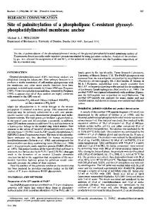
Figure 5. Control overhead with different number of communication sessions. 5000
Pr oposed Pr ot ocol GPSR SPEED
200
4
Communication Sessions
Figure 4. Packet delivery ratio with different number of communication sessions. 250
3
150
100
50
4000 3500 3000 2500 2000 1500 1000 500
0 1
2
3
4
5
6
7
8
9
10
Communication Sessions
Figure 6. Average delivery delay with different number of communication sessions.
A. Simulation Environments and Metrics The hole geometric modeling is implemented in Network Simulator Qualnet 3.8 and selects IEEE 802.11 as our MAC protocol. The transmission range of sensor nodes is 100m. The size of the sensor network is set to 1000*1000m2 where 1,000 nodes are randomly distributed. 5 sources and 5 destinations are moving with a random speed of 0~2m/s. And the destination location is known by the corresponding source. Each simulation lasted for 1000s. We use four metrics to evaluate the performance of Anchor Node Based Virtual Modeling of Holes. The packet delivery ratio is the ratio of the number of successfully delivered data packets to the number of data packets generated by the source. This metric reflects the data delivery efficiency. The average delivery delay is defined as the average time delay between the moment a source transmits a packet and the moment a destination receives the packet. This metric indicates how quick the destination can get data packets from the source. The control overhead is number of control packets generated during simulation time. Energy consumption is the total energy consumption of the nodes around the holes. The metric reflects the trend of the change of the network topology.
0 1
2
3
4
5
6
7
Communication Sessions
8
9
10
Figure 7. Energy consumption with different number of communication sessions.
B. Simulation Results Fig.4 shows the packet delivery ratio with different number of communication sessions. When there is only one communication session (one source and one destination), three protocols almost achieve the same packet delivery ratio. This is because almost no congestion occurs during simulation time. Only a few data packets may be lost due to source and destination mobility. With the number of communication session increasing, multiple communication sessions may bypass a hole simultaneously. GPSR and SPEED forward data packets along holes boundaries by the perimeter routing. So the probability that data congestions occur in the nodes around the hole is increased with an increasing number of communication sessions. However for our Anchor Node Based Virtual Modeling of Holes algorithm, the data packets are redirected to anchor location once they encounter a hole, the anchor location is different with different sources or destinations. Thus the probability of data congestions does not significantly increase with the increasing number of communication sessions. So we can see the packet delivery ratio of the proposed hole modeling does not significantly decrease with an increasing number of communication sessions. Fig.5 shows control overhead of three protocols. For GPSR, data packet delivery is purely according location information. All nodes need to update location information to neighbor nodes by beacon messages. This location update
This full text paper was peer reviewed at the direction of IEEE Communications Society subject matter experts for publication in the ICC 2008 proceedings.
scheme has no relation with the number of communication sessions. So there is nearly no change in control overhead with an increasing number of communication sessions. Comparing with GPSR, our algorithm includes an additional virtual circle construction process. But this virtual circle construction process also has no relation with the number of communication sessions since all node are assumed to be fixed in this paper, actually the overhead incurred by virtual circle construction is closely relate to the number and size of holes in sensor networks. SPEED focuses on finding a high speed data deliver path to forward data packet, so additional overhead was generated to find high speed path. This high speed path discovery process closely relates to the number of communication sessions. In addition, because of the data congestions in the nodes aground holes, SPEED needs to find other high speed path the to delivery data packets, this route rediscovery process is proportionately increased with increasing number of communication sessions. So the control overhead of SPEED significantly increases than other two protocols with an increasing number of communication sessions.
destination location. This means the data delivery path near a hole is different with variational source or destination location. The mechanism also counterpoises energy consumption of nodes near a hole.
Fig.6 shows the average delivery delay with an increasing number of communication sessions. When there is only one communication session, the average delivery of SPEED is lower than other two protocols since SPEED focuses on finding high speed paths for data delivery. However, when the number of communication sessions exceeds 2, the average delivery delay of SPEED significantly increases than other protocols. This is because the congestions occur on the boundary of hole. In SPEED, once a node checked data congestions, it needs to find a new high speed path, it is advisable for fixed source and destination. However for mobile source and destination, this route rediscovery process proportionately increases with source moving speed and the number of communication sessions. In our Anchor Node Based Virtual Modeling of Holes, data packets are redirected to anchor location once they encounter a hole. Anchor location is determined by source location, destination, and the information of the virtual circle. The data congestions seldom occur in the proposed scheme since the probability that more than one communication session sharing the some link is quite low. So the average delivery delay of our protocol does not increase significantly with the increasing number of communication sessions.
[1]
Fig.7 shows the total energy consumption of nodes on boundary of holes. GPSR and SPEED utilize perimeter routing to route data packet to destination when the data packet encounter a hole, in other words, as long as a hole locate between source and destination, the data packet must be sent along then boundary of the hole. Thus the energy consumption of the nodes on the boundary of holes is quite high in SPEED and GPSR. In our proposed algorithm, the data packet is redirected to an anchor location when the data packet encounters a hole. By this way to prevent data packet go along the boundary of holes. Thus reduce energy consumption of the nodes on the boundary of holes and prevent holes diffusion. Also, the anchor location closely relates to the source and the
VI.
CONCLUSIONS
In this paper we proposed an Anchor Node Based Virtual Modeling of Holes for Geographic Routing which models a hole by a virtual circle to solve the holes problem in wireless sensor network. After receiving a data packet, a node on the boundary of a hole inform the source about the virtual circle information, then the source sends the subsequent data packets to the destination via the anchor location, therefore bypassing hole area. This mechanism has two advantages that it reduces energy consumptions and data congestions of the node on the boundaries of holes. It prevents data packets from entering the stuck area of a hole and avoids the local minimum problem, thus reducing route rediscovery overhead. REFERENCES B. Karp, H.T. Kung “GPSR: Greedy perimeter stateless routing for wireless networks,” In Proc. of the 6th Annual Int'l Conf. on Mobile Computing and Networking. Boston: ACM Press, 2000. pp.243-254. [2] Q. Fang, J. Gao, und L. J. Guibas, “Locating and bypassing routing holes in sensor networks”. In INFOCOM 2004, vol.4, March 2004 pp.2458-2468 [3] P. Bose, P. Morin, I. Stojmenovic, and J. Urrutia. “Routing with guaranteed delivery in ad hoc wireless networks”, In Proc. of the 3rd International Workshop on Discrete Algorithms and Methods for Mobile Computing and Communications (DIALM'99), 1999, pp.48-55. [4] T. He, J.A. Stankovic, C. Lu and T.F. Abdelzaher, “A Spatiotemporal Communication Protocol for Wireless Sensor Networks,” IEEE Transactions on Parallel and Distributed Systems, VOL. 16, NO. 10, October 2005, pp.995-1006, [5] D. S. J. De Couto and R. Morris, “Location proxies and intermediate node forwarding for practical geographic forwarding,” Tech. Rep. MITLCS-. TR-824, MIT Laboratory for Computer Science, June 2001 [6] J. Li, J. Jannotti, D. DeCouto, D. Karger, and R. Morris, “A scalable location service for geographic ad-hoc routing.” In Proc. of the 6th Annual ACM/IEEE Int’l Conf. on Mobile Computing and Networking, 2000, pp.120-130. [7] S. Ratnasamy, B. Karp, L. Yin, F. Yu, D. Estrin, R. Govindan, and S. Shenker, “A Geographic Hash Table for Data-centric Storage,” In the First ACM International Workshop on Wireless Sensor Networks and Applications (WSNA). 2002, pp. 78-87. [8] J. Hightower and G. Borriello, “Location Systems for Ubiquitous Computing”. IEEE Computer, vol. 34, no. 8, August 2001, pp. 57-66. [9] A. Savvides, C.-C. Han, and M. B. Srivastava, “Dynamic Fine-grained Localization in ad-hoc networks of Sensors”. In Proc. MobiCom, 2001, pp.166-179. [10] A. Savvides and M. B. Strivastava, “Distributed Fine-grained localization in ad-hoc networks”, IEEE Transactions of Mobile Computing, 2003. [11] A. Ward, A. Jones, and A. Hopper, “A new location technique for the active office,” IEEE Personnel Communications, vol. 4, no. 5, October 1997, pp. 42-47. [12] J.A. Bondy and U.S.R. Murty, “Graph Theory with Applications,” (Elsevier North-Holland, 1976).