int. j. prod. res., 2002, vol. 40, no. 10, 2269±2288
An Internet-enabled image- and model-based virtual machining system Y. B. LUOy, S. K. ONGz, D. F. CHENy and A. Y. C. NEEz* Virtual reality (VR) can be described as a four-dimensional (4-D) simulation of the real world, including the 3-D geometry space, 1-D time and the immersive or semi-immersive interaction interface. VR applications in mechanical-related research areas are becoming popular, e.g. virtual layout design, virtual prototyping, Internet-based virtual manufacturing, etc. However, research in VR applications is facing con¯icting requirements for high rendering quality and near real-time interactivity. This paper represents an Internet-based virtual machining system that builds an integrated VR scene, which combines images and models, to overcome the above con¯icts. This research is divided into three parts: ®rst, image mosaics techniques are used to implement an Internet-based virtual workshop, which is an image-based virtual scene. The method of obtaining original sequential images, the principle of image mosaics to realize automatic seamless stitching, and projection transformation matrices to reconstruct a closed inward-facing space are presented. Secondly, a model-based virtual milling machine has been constructed with three detailed approaches: a category-based dynamic graph structure to support collision detection, a relation-oriented collision detection method to improve the e ciency of collision detection, and a dynamic modelling method to model a dynamic workpiece object. Finally, an Internet-based virtual milling system, which is the integration of the image-based virtual workshop and the model-based virtual CNC machine, is constructed using the reposition method to achieve visual consistency of the virtual objects and images. This system, which includes an integrated scene, combines the advantages of image-based VR and model-based VR. Consequently, this system has both high rendering quality and good real-time interactivity.
1.
Introduction There is an increased requirement for manufacturin g industries to achieve e ective, diverse, and small-lot production, so as to meet diversi®ed user needs. With the rapid progress in the web and the virtual reality (VR) technologies in the last few years, it becomes possible to implement Internet-based virtual machining systems to meet this requirement. VR can be described as a 4-D simulation of the real world, including the 3-D geometry space, 1-D time and the immersive or semi-immersive interaction interface. Generally, VR can be classi®ed as hardware-based VR and PC-based VR. A hardware-based VR system depends on special VR hardware, such as a head-mounted display, VR-mouse, etc. A PC-based VR system is implemented using software on PCs. It uses standard PC peripherals as input and output tools. Currently, a hardRevision received January 2002. { Institute of Intelligent Manufacture and Control, Wuhan University of Technology, Wuhan, People’s Republic of China. { Department of Mechanical Engineering, National University of Singapore, 10 Kent Ridge Crescent, 119260 Singapore. * To whom correspondence should be addressed. e-mail:
[email protected] International Journal of Production Research ISSN 0020±7543 print/ISSN 1366±588X online # 2002 Taylor & Francis Ltd http://www.tandf.co.uk/journals DOI: 10.1080/00207540210125498
2270
Y. B. Luo et al.
ware-based VR system can be considered an immersive virtual scene, while a PCbased VR system is a semi-immersive virtual scene. VR peripherals are too costly for many applications. As PC-based Internet technologies are developing rapidly, they present a promising alternative to hardware-based VR. There are two major methods to implement a PC-based VR system (Huang et al. 1998). In the image-based rendering method (IBRM), the virtual world builders take photographs at a set of viewpoints to generate a panorama for each viewpoint. The second method is the model-based rendering method (MBRM), where the virtual world builders construct virtual worlds by building a 3-D solid model for each object within the virtual environment. Both methods have their advantages and disadvantages. The major advantages of IBRM are as follows. (1) It is easy to construct a photo-quality virtual world with IBRM, and thus an IBRM system produces good realistic e ects. (2) The complexity of the virtual world construction is constant regardless of the complexity of the real world modelled. (3) It has good real-time interactivity due to low data demand, which depends only on the data of the images. However, although the realistic quality of the IBRM virtual environment can be very high, it is not considered to be very immersive because it lacks interactivity. The major interaction that an IBRM VR system provides is the virtual navigation, which includes functions such as turning and looking around, etc. The virtual scene cannot be manipulated because it is constructed with projected images and not solid objects. It is di cult for users to have immersive feelings in an IBRM virtual environment due to limited interactivity. Compared with IBRM, MBRM allows operators to interact with the contents of the virtual environment and thus has better interactivity. Operators can manipulate the objects in a MBRM virtual scene such as moving, rotating, etc. However, many disadvantage s tend to overwhelm the immersion e ect of a MBRM virtual environment. They are as follows. (1) Poor realistic e ects due to the arti®cially constructed models. (2) The complexity of the virtual world construction is proportional to the complexity of the real world. It will contain a large amount of data if the real world is complex. (3) It has poor real-time interactivity due to the large amount of data required. It is di cult to make users feel that they are travelling and exploring the virtual worlds freely if they have to wait a long time when transiting from one viewpoint to another, or moving an object. Virtual manufacturing (VM) is the integration of VR technology and manufacturing technologies. The scope of VM can range from an integration of the design sub-functions such as drafting, ®nite element analysis and prototyping to the complete functions within a manufacturing enterprise, such as planning, operation and control (Shukla et al. 1996). Application of VM technology has successfully reduced manufacturin g cost and time-to-market, leading to an improvement in productivity. Virtual machining is a major part of the VM technology. Traditional machining theories are mostly based on experimental data. In order to achieve optimum
Internet-enable d virtual machining system
2271
machining conditions from the cost and productivity viewpoint, large numbers of experiments have to be performed. When no suitable experimental data are available, operators tend to run machines under conservative conditions for reliable and safe performance. However, obtaining statistically reliable experimental machining data is extremely costly, both in terms of time and resources. Virtual machining technology can lower machining costs and improve productivity as machining plans can be simulated before being carried out on production lines. Current VR and web technologies provide the feasibility to implement a multiuser Internet-based virtual machining system. However, this is not an easy task due to the following factors. (1) The con¯icting requirements of real-time machining and rendering. Generally, a high level of detail for a scene description would result in a high complexity of the virtual scene. (2) The con¯icting requirements of a static data structure and dynamic modelling. In the virtual machining environment, a dynamically modelled workpiece is essential. (3) The requirements for a consistent environment to avoid confusion and provide navigational cues to prevent a user getting lost in the VR environment. (4) The importance of an adequate sense of immersion in the VR environment, without which even a highly detailed rendering will not help a user to interact e ectively in the virtual 3-D environment using conventional 2-D interfaces, such as a keyboard. A novel integrated VR scene, which integrates solid models into a 3-D virtual scene reconstructed with sequential images, is a good solution to overcome the above di culties. It combines the major advantages of IBRM and MBRM, and provides both good rendering quality and good real-time machining capability. This research is divided into three modules. (1) An image-based virtual workshop module is used to reconstruct a virtual workshop with sequential images of a real workshop. (2) A model-based virtual CNC milling machine module for constructing a machinable workpiece model with variable sizes using dynamic modelling techniques. (3) The module for the integration of the virtual CNC milling machine into the virtual workshop. This is implemented as a web-based multi-user virtual 3axis CNC milling machine system through the integration of images and models. 2.
Acquisition of sequential images In recent years, panoramic scene-stitching technology, which is a major approach to implement an IBRM VR environment with images, has become an alternative way to provide users with an immersive virtual world. To implement a VR system, cost is one of the main factors to be considered. Although many related commercial products using photographs taken by special equipment to implement image-based VR systems have been developed, automatic implementation of an image-based VR system with sequential images taken from a digital camera is still a di cult task. This research presents an economic way to implement a photo-quality VR environment
Y. B. Luo et al.
2272
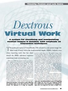
where hardware cost is a ordable to the general users, and only a PC and a digital camera are needed. A cylindrical texture mapping-based technology is used to produce automatically a closed inward-facing virtual scene with sequential images. This technology enables users to reconstruct 3-D inward-facing scenes easily with sequential images. To implement 3-D reconstruction automatically , the methodology to acquire sequential images is described as follows. (1) The focus centre of the camera must be ®xed. The camera should be rotated around a ®xed focus centre when taking sequential pictures. (2) The focus and aperture of the camera cannot be varied when taking sequential pictures. A varied focus and aperture will result in di erent brightness and contrast between the neighbouring pictures and lead to an inconsistent vision e ect. (3) There should be overlapping areas between neighbouring pictures. Figure 1 illustrates the way to obtain the sequential images. Using this approach, 12 sequential photographs for reconstructing a closed ®xed latitude space can be obtained. Figure 2 shows three sequential photographs of a workshop. It is evident that there are overlapping areas between the neighbouring photographs .
Figure 1.
(a)
Figure 2.
Method to acquire sequential images.
(b)
(c)
(a) First original photograph, (b) Second original photograph, (c) third original photograph.
Internet-enable d virtual machining system
2273
3.
Image-based virtual workshop reconstruction In order to construct an IBRM VR system, the closed image space should be constructed ®rst. The image-based inward-facing space reconstruction is a major part of the IBRM technique. In designing a shape reconstruction system, there are di erent engineering trade-o s. The main parameters to be considered are cost, accuracy, ease of use and the speed of acquisition. There are some hardwarebased 3-D reconstruction systems such as the laser scanning system (Laeng et al. 2000). Currently, most of the commercial 3-D scanners emphasize accuracy over other parameters. These systems use the routine motion of objects and the active lighting of a scene to capture accurate 3-D information but, unfortunately , they are expensive. Furthermore, most systems fail under bright outdoor scenes except for those based upon synchronized scanning.
3.1. Review of image-based 3-D reconstruction technologies One of the most valuable functions of a human visual system is the rich 3-D information feedback, such as the shapes and positions of the objects in the surroundings. Emphasizing low cost and simplicity, an interesting challenge (Bouguet and Perona 1999) for research in vision systems is to make better use of the data available from the images, to design an image-based 3-D reconstruction system that only uses a PC and a digital camera. The 3-D information of an object can be extracted from its images by two means: the single-eye simulation and the dual-eye simulation. The single-eye simulation calculates the 3-D positions of real points based on `weak structured lighting’. The dual-eye simulation calculates the 3-D positions of real points based on projective geometry principles. Approximate 3-D information can be obtained from the image of an object by using the single-eye vision simulation, while accurate 3D information can be obtained by using the dual-eye simulation. In the image-based inward-facing space reconstruction research area, the theory of projective and metric reconstruction from the semi-calibrated views has reached a good level of maturity in recent years (Hartley 1997). Recent reports (Brodsk et al. 2000, Molton and Brady 2000, Shum and Szeliski 2000) show that high quality reconstruction is now possible. In particular, many problems in reconstruction (Zhang 1998) have now been solved, such as the computation of the multi-focal tensors, particularly the fundamental matrix and trifocal tensors. On the other hand, there are some di culties in the software-based 3-D reconstruction ®eld. (1) There are currently few highly e ective algorithms available for automatic detection of overlaps in sequential images. (2) Rational application of bundle adjustment to solve more general reconstruction problems is still a di culty (Steven and Charles 1999). (3) In metric reconstruction (Pollefeys et al. 1998), minimal assumptions must be made on the camera matrices. (4) Although many methods, such as the iterative methods and the factorizationbased algorithms, have been attempted, there is no satisfactory algorithm for projective reconstruction from several views. (5) There are few e ective and feasible algorithms to automatically stitch and reconstruct sequential images to form a panoramic view.
Y. B. Luo et al.
2274
The objective of this research on image-based virtual workshop reconstruction is to implement a closed inward-facing virtual workshop scene with solid models of a CNC milling machine. This virtual workshop 3-D reconstruction system, which requires only a PC and a digital camera, is capable of producing photo-quality scenes. Users can navigate freely in the virtual workshop on the Internet. 3.2. Principles of image mosaics The image mosaics technology, which is a good approach to implement seamless image-based stitching, plays an important role in the ®eld of image-based rendering. Automatic construction of large, high-resolution image mosaics, which can be used for many di erent applications, such as the construction of large aerial and satellite photographs from a collection of images, is an active area of research in the ®elds of photogrammetry , computer vision, image processing, computer graphics, etc. It can also be used to reconstruct a 3-D closed space. Automatic detection of all the corresponding points in the overlapping areas of neighbouring images using arti®cial intelligence or fuzzy recognition technology is almost an inextricable di culty owing to the large numbers of similar points. The image mosaics technology avoids this di culty by detecting the corresponding lines instead. In two neighbouring images, a corresponding line, which consists of all the corresponding points in the images, can be detected using projective geometry analysis. The principles for the formation of the ®rst photograph (®gure 2(a)) and the second photograph (®gure 2(b)) are illustrated in ®gure 3. The ®rst photograph (®gure 2(a)), taken with ON at 08, was formatted on the formation plane AB, while the second photograph (®gure 2(b)), taken with OM at 308, was formatted on the formation plane CD. O is the focus centre of the camera. ON is the line of focus of the camera. Point G is actually a line containing all the intersection points of the formation plane AB and the formation plane CD. AK and JD are the overlapping areas between the ®rst photograph (®gure 2(a)) and the second photograph (®gure 2(b)). RAB is the projection point of any real point R on the formation plane AB. When the camera was rotated 308 around O to take the second photograph (®gure 2(a)),
Figure 3.
The principle of formations.
Internet-enable d virtual machining system
2275
CD became the formation plane, OM is the line of focus of the camera, and QCD is the projection of any real point Q on the formation plane CD. Consider a real point U, whose projection point UAB is in the plane AG, and its corresponding position UCD in the plane JG must be the intersection point of OU and CD. All the corresponding points in plane JD of the points in plane AK can be detected this way. With respect to a special point P, which is a real point in the extended line of OG, the corresponding lines in planes AB and CD can be detected. It is evident that PAB , which is the projection point of P on AB, and PCD , which is the projection point of P on CD, are identical with G. Consequently, the line G shown in ®gure 4 is the corresponding line of the ®rst photograph (®gure 2(a)) and the second photograph (®gure 2(b)). Apparently, if the ®rst photograph (®gure 2(a)) is placed at the position of AB and the second photograp h (®gure 2(b)) at CD, they can be seamlessly stitched to form an integrated picture as shown in ®gure 4, which is the image of the plane CGB. It can also be concluded that these pictures, placed at the positions where the formation planes were when they were taken, can be seamlessly stitched to form a closed space. Arranged according to ®gure 1, these 12 original sequential pictures can be stitched to construct the virtual workshop. 3.3. Calculation of the focus of the camera The traditional techniques of 3-D reconstruction entail the extraction of camera matrices, which is a very complex process. The method of 3-D reconstruction based on projective geometry principles avoids the extraction of camera matrices. As presented earlier, the only key problem of placing the pictures at the positions where the picture planes are when they are taken, is the calculation of the focus of the camera. However, the calculation of the focus of the camera is relatively simple compared with the extraction of the camera matrices. The principles for calculating the focus of the camera are shown in ®gure 5. A real point T projected on the overlapping areas of the neighbouring images as TAB
G
Figure 4.
The method of image mosaics.
Y. B. Luo et al.
2276
Figure 5.
The principle to calculate the focus of camera.
and TCD is ®rst marked. In equation (1), MON is the rotation angle of the focus axis, which is 308 in this case. The values of TAB N and TCD M can be obtained easily by image processing. OM ˆ ON. It is evident that NOTAB , MOTAB and ON, which is the focus of the camera, can be determined easily. Note that all variables excluding the angles are measured as the number of pixels. 9 TAB N > ; > > > ON > = TCD M tan MOT AB ˆ ; > > > OM > > ; NOT AB ‡ MOT AB ˆ MON : tan NOT AB ˆ
…1†
3.4. Automatic construction of a closed space For applications such as virtual workshop navigation and architectural walkthroughs, it is desirable to have complete panoramic views, allowing a user to look in any direction. The traditional image-stitching algorithm is too complex and it has limited the users of mosaic building to researchers and professional photographers . An objective of this research is to enable any user to construct a full panoramic mosaic view with sequential images, employing matrix transformation technologies. A closed texture mapping space is automatically built by associating a rotation matrix with each input image. An original image containing m £ n pixels can be de®ned as the matrix I, as shown in equation (2), where c is the matrix as shown in equation (3) de®ning the colour of a pixel. Any point in a 3-D space can be de®ned as matrix P, as shown in equation (4), containing the position and colour information. As shown in ®gure 6, these original images are supposed to be placed at the focus centre and parallel to the ®rst formation plane initially. z in matrix P in equation (4) of these original images is equal to 0.
Internet-enable d virtual machining system
Figure 6.
2277
Process to build horizontal closed space.
2
c1;1
c1;2
6c 6 2;1 Iˆ6 4 ¢¢¢
¢¢¢ ¢¢¢
cm;1
¢¢¢
¢¢¢
c1;n
¢¢¢ 7 7 7 ¢¢¢ 5
¢¢¢ ¢¢¢ ¢¢¢
…3†
3
x
6 y 7 6 7 6 7 7 z Pˆ6 6 7 6 7 4 1 5 cx;y;z 2
…4†
1
0
0
60 6 Ttranslation ˆ 6 40
1
0
0
1
0
0
0
…2†
cm;n
c ˆ ‰RGBŠT 2
3
0
3
0 7 7 7: OM 5
…5†
1
The ®rst image, associated with matrix Ttranslation as shown in equation (5), can be moved from the focus centre to the position of image 1, as illustrated in ®gure 6. Any point in the ®rst original picture can be projected to image 1 according to equation (6). P 0 ˆ Ttranslation £ P
…6†
Y. B. Luo et al.
2278
Figure 7.
Part of the closed inward-facing space.
2
cos ³
6 0 6 Trotation ˆ 6 4 ¡ sin ³ 0
0
sin ³
1
0
0
cos ³
0
0
0
3
07 7 7: 05
…7†
1
The second image, associated with the matrix T2 as shown in equation (10), can ®rst be rotated ³ (308 in this case) around the focus centre, and moved to the position of image 2. Any point in the second original picture can be projected onto image 2 using equation (8). P 0 ˆ Trotation £ Ttranslation £ P
…8†
T1 ˆ Ttranslation
…9†
T2 ˆ Trotation £ Ttranslation
…10†
Tn ˆ Trotation £ Tn¡1 ; n ˆ 3; 4; . . . ; 12
…11†
P 0 ˆ Tn £ P:
…12†
The following sequential images, associated respectively with Tn in equation (11), can be rotated and translated to the respective positions as well. The closed texture mapping space can be constructed automatically with these 12 sequential images according to equations (6), (8), and (12). Figure 7 is part of the stitched closed inward-facing virtual workshop. 4.
Relation-oriented collision detection method The virtual workshop can be navigated but cannot be manipulated freely. The users are merely spectators and cannot interact with the contents of the virtual workshop. For a virtual manufacturing system, interactions are vitally important. MBRM is used to construct solid models of the CNC milling machine. 3-D collision detection is a core component in a VM system (Lin and Chen 2001). However, there is currently no e cient topology architecture that can support collision detection and overlap checks. Given certain geometric models, such as a workpiece and a cutter, the goal of collision detection is to check whether they overlap at a given time instance. It is a special case of distance determination, where the distance between objects is equal to or less than zero. Most researchers working on collision detection are in the ®elds of robotics, CAD/CAM and computer graphics. In a virtual CNC milling system, collision detection is crucial for the implementation of real-time machining.
Internet-enable d virtual machining system
2279
The current techniques in collision detection face two issues. The ®rst issue is to reduce the computational time of collision detection algorithms since collision detection is usually the most time-consuming component of many geometric reasoning applications. The second issue is the so-called `all-pairs weakness’ that checks all pairs of geometric primitives, such as polygons, between two objects. This approach is deemed to be very ine cient. Therefore, most research e orts focus on reducing the number of collision checks between two geometric primitives. This research presents a novel category-base d dynamic graph (CDG) structure, which is de®ned as a graph with categorized vertices and dynamic edges to overcome the above two issues. In many current cases, 90% of the overall computational time is spent on detecting collisions or computing distances between polygons. Aiming at reducing the number of time-consuming collision checks, all virtual objects in this virtual CNC environment are approximated as cylindrical and cubic descriptions. All virtual objects in the virtual CNC environment are categorized into three kinds of objects initially: dynamic objects, whose shapes can be modi®ed in real-time, such as the workpiece; motion objects, whose positions can be changed; and static objects, whose shapes and positions remain constant during the entire process. A MBRM VR system involving ®ve objects is taken as an example. Its CDG is clearly illustrated in ®gure 8. Every vertex in the CDG representing an object is a class type consisting of ®ve attributes, viz., name, category, centre position, pro®le function and the motion function. Every edge in the CDG representing the relation between two objects is a class type with two attributes; namely, the attached motion and the distance between the two objects. These abstract recursion class types are de®ned as follows. Class Type CDG_vertex { public: string name; string category; CDG_vertex which_attached_to ; point centre; published:
Attribute 1
Attached motion Object A
Attribute 2
Collision detection function
Attribute 3
Object E
Object B Attribute 4 Attribute 5 Object C
Object D Figure 8.
CDG structure.
2280
Y. B. Luo et al.
¯oat motion_function; /* The motion function inherits the which_attached_to.motion_functio n */ private: ¯oat pro®le_function; } Class Type CDG_edge { CDG_vertex object1; CDG_vertex object2; bool attached_motion ; /* The value of the attached_motio n is true only if object1. which_attached_t o equal to object2 or object2. which_attached_to equals to object1 */ bool detection_function ; /* The detection_functio n will call CDG_vertex.motion_functio n and CDG_vertex. pro®le_function */ } The calls to the collision detection (detection_function ) function will be ignored in the following cases. (1) Both object1.category and object2.category have static values; and (2) The value of the attached_motio n is true, namely the motion of a vertex of an edge is associated with the other vertex of this edge. Almost all the current collision detection techniques reported in literature are object-oriented methods that solely detect the collision between two objects in a given time instance twice. CDG provides an opportunit y to implement a relationoriented method to avoid this problem because the collision reports are determined only by the collision detection function of the edge. The relation-oriented CDG-based method greatly reduces the computational time. For a virtual scene comprising n objects, in which m objects are static, and s edges, whose values of attached_motio n are true, most collision detection algorithms involving the `all-pairs weakness’ problem have a computational time of T …n† ˆ …n ¡ 1† £ n. Since the edges associated with two static objects or attached objects are ignored, the computationa l time of the relation-oriented algorithm is reduced to: T …n† ˆ …n ¡ 1† ‡ …n ¡ 2† ‡ ¢ ¢ ¢ ‡ 1 ¡ …m ¡ 1† ¡ …m ¡ 2† ¡ ¢ ¢ ¢ ¡ 1 ¡ s ˆ ‰n £ …n ¡ 1† ¡ m £ …m ¡ 1† ¡ 2 £ sŠ=2: Generally, most objects in a virtual environment are static. Therefore, in a virtual environment involving a few motion objects, the relation-oriented CDG-based method avoids the unnecessary checking and reduces the computationa l time. The virtual 3-axis CNC milling machine consists of about 30 objects that are categorised into ®ve blocks, as illustrated in ®gure 9. Motion block 1 can move along the x-axis and the y-axis. Motion block 2 attached to motion block 1 can move along the x-axis and the y-axis with motion block 1, can move along the z-axis by itself, and rotate around the z-axis by itself. The static block 3 is always constant during the entire process. The dynamic block 4 attached to the motion block 5 is a machinable workpiece with variable sizes. Motion block 5 attached with the dynamic block 4 can move along the z-axis. Although the virtual CNC machine comprises many objects, the experimental result is quite good even when it is rendered on a low-end client personal computer. The virtual machining process has good real-time capability.
Internet-enable d virtual machining system
2281 Motion block 1 Attached to Motion block 2 Static block 3 Dynamic block 4 23 Attached to Motion block 5
Figure 9.
Structures of virtual CNC machine.
This demonstrates the e ectiveness of the relation-oriented CDG-based algorithm for the virtual CNC machining system.
5.
A machinable workpiece conforming to tool motions Currently, many 3-D modelling packages are available such as the OpenGL, and the Direct3D soft packages. However, when a model constructed with a current 3-D modelling package is immersed in a virtual environment, its pro®le function cannot be modi®ed in real time. The representation of the real-time workpiece material removal process is very important in the simulation of the machining process. Accurate monitoring of the workpiece removal process will enable a user to evaluate the machining process easily (Li 2001, Lamberson and Wasserman 2001). In a virtual machining system, the workpiece should be represented with a dynamic model to implement real-time machining. Unfortunately , there is currently little research on real-time dynamic modelling. This research does, however, employ the VRML ElevationGrid node attached to the metal light e ect to implement a machinable workpiece conforming to tool motions. The material removal process of a workpiece represented by the ElevationGrid node has very good real-time interactivity because the ElevationGrid node provides better compression than some other VRML dynamic nodes, and thus shorter download time. The representation of the workpiece consists of a uniform rectangular grid of varying height in the Y ˆ 0 plane of the local coordinate system. The geometry is described by a scalar array of height values that specify the height of a surface above each point of the grid. The xDimension and zDimension ®elds indicate the number of elements of the grid height array in the X and Z directions. The vertex locations for the rectangles are de®ned by the height ®eld, xSpacing and the zSpacing ®elds. The height ®eld is an xDimension £ zDimension array of scalar values, representing the height above the grid for each vertex. A geometric model of a workpiece with a width of 0.9 units and a length of 2.0 units is shown in ®gure 10. The size of the workpiece can be de®ned by the xDimension, zDimension, xSpacing, zSpacing, and the array representing the height ®eld. Overlap checks are fundamental for implementing the real-time workpiece material removal process. As the workpiece has a box shape and the cutter has a
Y. B. Luo et al.
2282
=0.3
=0.5 Figure 10.
Representation of dynamic workpiece.
cylindrical shape, it is quite easy to implement overlap checks. Figure 11 shows the principle of overlap checks. When a user inputs the G-code at the client end on the Internet, the G-code will be transformed to the motion equation of the cutter with a special transformation function. The application calls the overlap checks routine for every given time instance. When an overlap is detected, the heights of these vertices inside the circle of the cutter will be set equal to the height of the cutter. All the virtual objects in the virtual scene are respectively attached with the detailed metal lighting models so that the virtual scene has a realistic visual e ect. In order to implement real-time G-code input and real-time workpiece machining, the transformatio n function ®rstly obtains information on the key positions from the input G-code. Next, it employs interpolation techniques to determine the
The
heights
of
these
vertices in the circle of the
Cutter
cutter will be changed in real-time.
Workpiece
Figure 11.
Overlap checks.
Internet-enable d virtual machining system
2283
motion tracking of the cutter. Figure 12 is a simple case of G-code input at a client end on the Internet. Figure 13 shows the real-time machining process and the machining result of the input G-code. In the same way, any machining process of any complex G-code can be simulated.
Figure 12.
Figure 13.
A case of input G-code.
The virtual machining process and result of the G-code shown in ®gure 12.
Y. B. Luo et al.
2284 6.
Integration of virtual objects with the virtual workshop The IBRM and MBRM contain objects with di erent attributes. A MBRM scene comprises solid objects, while an IBRM scene is reconstructed with projected images. The task of combining these objects with di erent attributes is di cult. Geometrical consistency is a major part of vision consistency, which includes static and dynamic geometric consistency. Static geometrical consistency demands the size and perspective relations of the virtual objects to be consistent with the closed virtual scene reconstructed from stitched sequential images. Dynamic geometrical consistency requires the same consistency during motion. For example, if a user navigates an integrated VR environment, geometrically correct integrated scenes should be generated during any free motion. Currently, an estimated camera position is used to meet vision consistency. In this research, the original pictures were taken using a ®xed rotation routine, i.e. the reconstructed virtual environment has a pre-de®ned coordinate system. Therefore, an estimation of the positions of virtual objects instead of the camera position is necessary to meet the pre-de®ned perspective relation. The virtual object position estimation problem consists of determining the position and orientation of the models with respect to, and consistent with, the mosaic scene images. Making a set of corresponding 3-D points in a virtual object consistent with the 2-D points in an image solves the problem of position estimation. Virtual object 1 in ®gure 16, later, is a virtual object immersed in the image-based reconstructed virtual environment. The image plane in ®gure 14 is a projected image containing the image of the real object associated with virtual object 1. It is evident that the solid virtual object can meet the vision consistency requirement with respect to the image representation of the virtual object, as shown in ®gure 16, if it is translated and rotated to the position of virtual object 2. Even when the complete virtual scene is moved or rotated during navigation, vision consistency can be maintained. First, three points are selected, such as A, B and C in virtual object 1, as are three corresponding points in the image plane, such as A2, B2 and C2. The coordinates of
Image of real object Virtual object 2
Virtual object 1
Figure 14.
Principle of projection relation consistency.
Internet-enable d virtual machining system
2285
A2, B2 and C2 can be worked out easily using image processing techniques. It is easy to determine the relative positions of A1, B1 and C1 since their relative positions are the same as A, B and C. This principle can be illustrated more clearly in 2-D geometry graphics, as shown in ®gure 15. In ®gure 15, A, B and C are three points in a real object, and A1, B1 and C1 are the corresponding points of A, B and C in the virtual object. A3, B3 and C3 are the formatted image points of A, B and C on the image plane. OM is the focus of the camera. In the coordinate system of xOy, the coordinates of A3, B3 and C3 can be determined using image processing techniques, and the relative positions of A1, B1 and C1 are constant. Obviously, the positions of A2, B2 and C2 can be obtained easily. The points of A1, B1 and C1 can be moved to the positions of A2, B2 and C2 by translating and rotating to meet the vision consistency requirement. Even when OM is rotated to ON, namely the projected points are A4, B4 and C4 instead, vision
y x
Figure 15.
Principle of vision consistency in 2-D graphics.
Images
Virtual models
Figure 16.
Virtual environment combining images and models.
Y. B. Luo et al.
2286
consistency can still be maintained. The entire virtual object can be moved when its motion is attached to the three points and it can still meet the vision consistency requirement. Figure 16 is the virtual milling environment that combines images and models, and satis®es the vision consistency requirement well. The virtual milling environment has a very good visual e ect due to the consistent light e ect of the models and the images.
7.
Conclusions This research presents approache s to overcome the problems of IBRM and MBRM; namely, the methods to obtain original images, detailed projection translation methods to implement an image-based virtual workshop, CDG structure to support collision detection, a relation-based method to improve the e ciency of collision detection, and workpiece dynamic modelling. Based on studies on the key technologies of implementing an integrated VR scene, which combines the advantages of IBRM and MBRM, this research constructs an Internet-based multi-user virtual 3-axis CNC milling system. The system combines the advantages of image-based VR and model-based VR. The architecture of the system is shown in ®gure 17. The interface of this system is shown in ®gure 18. The software system was coded in VRML and Java. Users can navigate the virtual workshop and pre-de®ne machining tasks freely on the client ends of the Internet. The user-de®ned machining tasks can be evaluated and optimized in this system.
Virtual milling machine (models)
Virtual workshop (images)
Server
Internet
Client Figure 17.
Client
Client
…
Architecture of internet-based virtual CNC milling system combining images and models.
Internet-enable d virtual machining system
2287
Images of the workshop
Models of the milling machine
Feedback information
The position of cutter
Figure 18.
Input G-code
29
The interface of the internet-based virtual CNC milling system.
Acknowledgements This research was funded by the Singapore±China joint project `IT Applications in E-Manufacturing ’ (NSTB/172/2/1-17) supported by the National Science and Technology Board (NSTB) of Singapore, project `A PC-based VR System Combining Images and Geometry Scenes’, and the project `Study on the PC-based Distributed Virtual Design and Virtual Manufacturin g System’ supported by the Ministry of Education, People’s Republic of China. References B OUGUET, J. Y. and PERON A, P., 1999, 3D photography using shadows in dual space geometry. International Journal of Computer Vision, 35, 129±149. B RODSK, T., F ERMU LLER, C. and A LOI MON OS, Y., 2000, Structure from motion: beyond the epipolar constraint. International Journal of Computer Vision, 37, 231±258. H ARTLEY, R. I., 1997, Lines and points in three views and the trifocal tensor. International Journal of Computer Vision, 22, 125±140. H U ANG, H. C., N AI N, S. H., HUNG, Y. P. and CHENG, T., 1998, Disparity-based view morphing±a new technique for image-based rendering. Virtual Reality Software and Technology: Proceedings of the ACM Symposium on Virtual Reality Software and Technology, Taipei, Taiwan, pp. 9±16. L AENG, J., STE WART, J. G. and L IOU, F. W., 2000, Laser metal forming processes for rapid prototyping±a review. International Journal of Production Research, 38, 3973±3996. L AMBERSON, L. R. and W ASSER MAN, G. S., 2001, Monitoring manufacturing system availability. International Journal of Production Research, 39, 727±736. L I, X. L., 2001, Real-time tool wear condition monitoring in turning. International Journal of Production Research, 39, 981±992. L IN , Z. C. and C H EN, C. C., 2001, Collision-free path planning for coordinate measurement machine probe. International Journal of Production Research, 39, 1969±1992.
2288
Internet-enable d virtual machining system
M OL TON, N. and B RAD Y, M., 2000, Practical structure and motion from stereo when motion is unconstrained. International Journal of Computer Vision, 39, 5±23. POLLEF EYS, M., K OCH, R. and G OOL, L. V., 1998, Self-calibration and metric-reconstruction in spite of varying and unknown internal camera parameters. Proceedings of the International Conference on Computer Vision. pp. 90±95. SH UK LA, C., N AZQUEZ, M. and C HEN, F. F., 1996, Virtual manufacturing: an overview. Computers & Industrial Engineering, 31, 79±82. SH UM, H. Y. and S ZELISKI, R., 2000, Systems and experiment paper: construction of panoramic image mosaics with global and local alignment. International Journal of Computer Vision, 36, 101±130. ST EVEN, M. S. and C H ARLES, R. D., 1999, Photo-realistic scene reconstruction by voxel colouring. International Journal of Computer Vision, 35, 151±173. Z HA NG, Z. Y., 1998, Determining the epipolar geometry and its uncertainty: a review. International Journal of Computer Vision, 27, 161±195.