1
Android/Tizen based Artificial Intelligence techniques for Prognosis and Diagnosis of Electrical Machines* K.V.Satya Bharath† and Sheikh Suhail Muhammad M.Tech (Power Systems), Amity School of Engineering and Technology Amity University, Noida, Uttar Pradesh-201313, India †E-mail: kurukuru.bharath@student .amity.edu E-mail :
[email protected] Prof. (Dr.) Priya Ranjan Profesor-EEE, Amity School of Engineering and Technology Amity University, Noida, Uttar Pradesh-201313, India E-mail:
[email protected] Electric machines are widely used in the present day industries which constitute about a 75-80% of the total deployed due to their user-friendly interface. Generally speaking machinery is prone to multiple types of faults and an intelligent monitoring layer can ensure smooth operation and inform as maintenance alerts. In this work we present and ANDROID/TIZEN interface which integrates multiple AI and signal processing techniques to detect the different faults interrupting smooth performance of machinery in a very short span of time. We demonstrate the thought process, simulation, final software interface and test results to confirm its effectiveness. Keywords: Prognosis and Diagnosis, AI, ANDROID, TIZEN.
I.
Introduction
Induction motors are most commonly used electrical machines in industry because of their low cost, reasonably small size, ruggedness, low maintenance, and operation with an easily available power supply. Although these are very reliable, they are subjected to different modes of failures / faults. These faults may be inherent to the machine itself or due to operating conditions. The inherent faults may be are due to the mechanical or electrical forces acting on the machine enclosure. If a fault is not detected or if it is allowed to develop further it may lead to a failure. A variety of machine faults have been studied in the literature such as winding faults, unbalanced stator and rotor parameters, broken rotor bars, eccentricity and bearing faults.
2
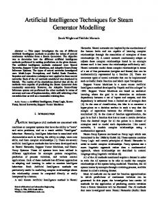
Fig: 1 Sources of Motor Faults
Several fault identification method have been developed and been effectively applied to detect machine faults at different stages by using different machine variables, such as current, voltage, speed, efficiency, temperature and vibrations. Thus, for safety and economic considerations, it is essential to monitor the behavior of motors of different sizes such as large and small. Traditionally maintenance procedures in industry follow two approaches as follows. The first one is to perform fixed time interval maintenance, where the engineers take advantage of slower production cycles to fully inspect all aspects of the machinery. The second is to simply respond to the plant failure as and when it happens. However, making use of today’s technology, new scientific approach was becoming possible for maintenance management. One of the key elements to this new approach is predictive maintenance through condition monitoring, which depends upon the condition of the plant. Condition monitoring is used for achieves performance of machinery, reducing consequential damage, increasing machine life, reducing spare parts inventories and reducing breakdown maintenance. An efficient condition-monitoring scheme is one that provides warning and predicts the faults at early stages. Monitoring system obtains information about the machine in the form of primary data and through the use of modern signal processing techniques it is possible to give vital diagnostic information to equipment operator before it catastrophically fails. The problem with this approach is that the results require constant human interpretation. The logical progression of the conditionmonitoring technologies is the automation of the diagnostic process. To automate the diagnostic process, recently a number of soft computing diagnostic techniques have been proposed. Recently soft computing techniques such as expert system, neural network, fuzzy logic, adaptive neural fuzzy inference system, genetic algorithm etc. have been employed to assist the diagnostic task
3
to correctly interpret the fault data. These techniques have gained popularity over other conventional techniques. These are easy to extend and modify besides their improved performance. The neural network can represent any non-linear model without knowledge of its actual structure and can give result in a short time. From the early stages of developing electrical machines, researchers have been engaged in developing a method for machine analysis, protection and maintenance. The use of above technique increases the precision and accuracy of the monitoring systems. The area of condition monitoring and faults diagnostic of electrical drives is essentially related to a number of subjects, such as electrical machines, methods of monitoring, reliability and maintenance, instrumentation, signal processing and intelligent systems. II.
Literature Review
Condition monitoring is defined as the continuous evaluation of the health of the plant and equipment throughout its service life. It’s important to detect faults while they are still developing. This is called incipient failure [1] detection. The incipient detection of motor failures also provides a safe operating environment. It is becoming increasingly important to use comprehensive condition monitoring schemes for continuous assessment of the electrical condition of electrical machine. By using the condition monitoring, it is possible to provide adequate warning of imminent failure. In addition, it is also possible to schedule future preventive maintenance and repair work. This can result in minimum down time and optimum maintenance schedules. Condition monitoring and fault diagnosis scheme allows the machine operator to have necessary spare parts before the machine is stripped down, thereby reducing outage times. Therefore, effective condition monitoring of electric machines is critical in improving the reliability, safety, and productivity. 2.1 Existing condition monitoring techniques:
Fig: 2 Types of fault diagnosis techniques for electric motors
4
Isermann[2] has presented a novel, unified model based fault detection and prediction (FDP) technique is developed for non linear multiple-inputmultiple-output (MIMO) discrete time systems. The proposed scheme addresses both state and output faults by considering separate time profiles. The faults, which could be incipient or abrupt, are modeled using input and output signals of the system. The fault detection (FD) scheme comprises online approximation in discrete time (OLAD) with a robust adaptive term. An output residual is generated by comparing the fault detection (FD) estimator output with that of the measured system output. A fault is detected when this output residuals exceeds a predefined threshold. The asymptotic stability of the fault detection and prediction (FDP) scheme enhances the detection and time to failure accuracy. The effectiveness of the proposed approach is demonstrated by using a fourth-order MIMO satellite system. Arkan,[3] Kostic-Perovic and Unsworth have presented two orthogonal axis models of a three phase induction motor. From these two models first one having asymmetrical windings and the other one having inter-turn short circuits on the stator winding. The machine is modeled by using classical two axis theory, and the equations are modified to take into account the stator inter-turn faults. A state space form of the system is presented for dynamic simulations. The simulation results from the models are compared with experiment carried out on a specially wound motor with taps to allow different number of turns to be shorted. The above models have been successfully used to study the transient and steady state behavior of the induction motor with short circuited turns. 2.2 Signal Processing Technique: Stainislaw [4], A.H.M sadrul Ula and Andrzej have proposed a new methodology for the signature analysis of induction motors, namely the instantaneous power. In this paper in place of stator current the instantaneous power is used for the motor signature analysis for the detection of mechanical abnormalities in a drive system. The information carried by the instantaneous power is the product of the supply voltage and current is higher than that deducible from the current alone. In the power spectrum of stator current the highest magnitude will appear is -52 dB, but in case of spectrum of instantaneous power the highest magnitude appears is -47dB. From the above the instantaneous power is higher by 5dB than that of the strongest non fundamental spectral component. Yen [5] and Lin have employed a wavelet packet for extracting useful information from vibration signals of an induction motor. Though the measured vibration signals contain non-stationary part, Fourier transform cannot provide sufficient information to detect some machine faults. The results of employing wavelet packet are used with the aid of statistical based feature selection criteria to discard the feature components containing little discriminate information. The
5
extracted reduced dimensional feature vector is then used as the input to the neural network classifier. The results show improvement in neural network generalization capability and significant reduction in training time. Douglas [6], Pillay and Ziarani have introduced a new algorithm, where they followed the least squares error minimization using the method of gradient descent in a time varying set of equations. The algorithm is used for transient motor current signature analysis using wavelets. Here the residual currents are analyzed using wavelets for the detection of broken rotor bars. The advantage of this method is that it does not required parameters such as speed or number of rotor bars. Here a high order notch filter is used to separate the fundamental frequency from the rotor bar frequencies. Once the fundamental frequency has been removed, the residual current can be examined by using discrete wavelet transform analysis. Hence Daubechies 8 wavelet is used as the mother wavelet function. From the results it is clear that the broken rotor bar can be detected using measured transient in rush current. 2.3 Soft Computing Technique Nejjari [8] and Benbouzid have used the Park’s vector patterns for detecting different types of supply faults, such as voltage imbalance and single phasing. In addition a neural network based back propagation algorithm is used to obtain the machine condition by testing the shape of the Park’s vector patterns. Two neural network based approach have been used, these are classical and decentralized. The generality of the proposed methodology has been experimentally tested and the authors claim that the results provide a satisfactory level of accuracy. III.
Motor Condition Monitoring Using Stator Current
Fuzzy subsets can be assigned to describe the stator current amplitudes by means of corresponding membership functions. A knowledge base pertaining to situations liable for faults in the motor comprising rule base and data base can be built to activate the fuzzy inference. The induction motor condition can thus be diagnosed using an apparatus of fuzzy inference. Induction motor under consideration is of 2-KW, 220/380 V, 15/8.6 A, 50-Hz, 4 pole, Δ connected squirrel cage type. The judgment of induction motor condition made based on fuzzy inference is capable of better diagnosis as it shares the human’s knowledge expressed in vague terms with computing abilities and knowledge based training etc. Such linguistic input prepositions can be directly expressed by Fuzzy System. The structure of Fuzzy Monitoring and Diagnosis is shown in Fig.3 and Fig.4.
6
Fig: 3 motor condition status Inputs/Outputs
Fig: 4 Schematic representation of Motor condition Diagnosis layout
The stator current signal reciprocates the promising information relating to motor fault. The Fuzzy systems rely on a set of rules. These rules allow the input to be fuzzy permitting the words to describe the fault conditions bringing a sort of robustness in information processing. Motor being an electromechanical system, the applied voltage, current drawn by the motor and internal temperature play a major role in reciprocating the faults. In the present study the motor phase currents have been monitored and based on the subsequent trend in the current values diagnosis of motor status has been judged. For Fault Detection and Diagnosis of Induction Motor stator current amplitudes Ia, Ib, Ic have been considered as the input variables to the fuzzy systems. The motor condition, Mc has been chosen as the output variable. We have defined the fuzzy subsets Ĩa Ĩb and Ĩc for input variables given to the fuzzy subsets and ḾC for output variables as followsµ𝑎(𝑖𝑎)⁄ Ĩ𝑎 = 𝑖𝑎 , Ɐ ia ∈ Ia µ𝑏(𝑖𝑏)⁄ Ĩ𝑏 = 𝑖𝑏 , Ɐ ib ∈ Ib
7
µ𝑐(𝑖𝑐)⁄ 𝑖𝑐 , Ɐ ic ∈ Ic µ𝑚𝑐(𝑚𝑐)⁄ Ḿ𝐶 = 𝑚𝑐 , Ɐ mc ∈ Mc Where ia, ib, ic and are elements of the discrete Universe of Discourse (UoD) i.e., Ia, Ib, Ic and Mc. Fuzzy logic works with linguistic variables whose values are words or sentences in a natural or artificial language. This provides a means of systematic manipulation of vague and imprecise information. The term set (T) is a collection of linguistic values assigned to linguistic variable. The term sets used for stator current and motor condition are as followsT (Ia, Ib, Ic) = {Zero (Z), Small(S), Medium (M), Big (B), Very Big (VB)} T (Mc) = {Open Phase, Damage, Critically Overloaded, Overloaded, Good} The optimized rule base has been developed so as to encompass all possible healthy and faulty conditions of the motor. Ĩ𝑐 =
IV. .
Fuzzy And Membership Functions Construction
Fig: 5 Linguistic Variable of Electric Motor Condition
This is the critical part of any Fuzzy System. After keen study of motor and fault prone situation we could identify different situations where motor condition is unhealthy. The inference rules can be classified into six distinct categories based on consequent parts. These rules along with their firing weights are enlisted as1) If Ia is Very Big then Mc is Damaged 2) If Ib is Very Big then Mc is Damaged 3) If Ic is Very Big then Mc is Damaged 4) If Ia is Big then Mc is Critically Overloaded 5) If Ib is Big then Mc is Critically Overloaded
8
6) 7) 8) 9) 10) 11) 12) 13) 14) 15) 16) 17)
If Ic is Big then Mc is Critically Overloaded If Ia is Small and Ib is Small and Ic is zero then Mc is Good If Ia is Small and Ib is Small and Ic is Medium then Mc is Overloaded If Ia is Small and Ib is Small and Ic is PS then Mc is Damaged If Ia is Small and Ib is Zero and Ic is Small then Mc is Damaged If Ia is Small and Ib is Medium and Ic is Small then Mc is Damaged If Ia is Zero and Ib is Small and Ic is Small then Mc is Damaged If Ia is Medium and Ib is Small and Ic is Small then Mc is Damaged If Ia is Small and Ib is Zero and Ic is Zero then Mc is Damaged If Ia is Small and Ib is Zero and Ic is Medium then Mc is Over Loaded If Ia is Small and Ib is Medium and Ic is Zero then Mc is Over Loaded If Ia is Small and Ib is Medium and Ic is Medium then Mc is Over Loaded 18) If Ia is Zero and Ib is Small and Ic is Zero then Mc is Damaged 19) If Ia is Zero and Ib is Small and Ic is Medium then Mc is Over Loaded 20) If Ia is Medium and Ib is Small and Ic is Zero then Mc is Over Loaded 21) If Ia is Medium and Ib is Small and Ic is Medium then Mc is Damaged 22) If Ia is Zero and Ib is Zero and Ic is Small then Mc is Damaged 23) If Ia is Medium and Ib is Zero and Ic is Small then Mc is Over Loaded 24) If Ia is Zero and Ib is Medium and Ic is Small then Mc is Over Loaded 25) If Ia is Zero and Ib is Medium and Ic is Zero then Mc is Damaged 26) If Ia is Zero and Ib is Medium and Ic is Medium then Mc is Damaged 27) If Ia is Zero and Ib is Zero and Ic is Medium then Mc is Damaged 28) If Ia is Medium and Ib is Zero and Ic is Zero then Mc is Damaged 29) If Ia is Zero and Ib is Zero and Ic is Zero then CM is Good 30) If Ia is Medium and Ib is Medium and Ic is Zero then MC is Good 31) If Ia is Zero and Ib is Medium and Ic is Medium then Mc is Good. After vigorous analysis of all rules we could develop a rule base comprising only 5 rules covering whole health condition of motor.
Table: 1 Rule Base for Motor Health
9
By Inference input conditions of stator currents are mapped with consequential output motor health conditions and output on the health of the motor at any instant of time is derived. It is followed by the process of De-fuzzy for computing crisp indication of motor health condition based on the fuzzy output generated by rule firing process of Fuzzy Inference. There are many types of de-fuzzy methods available. But we have employed the Centre of Area (COA) method for de-fuzzy. Despite its complexity it is more popularly used because, if the areas of two or more contributing rules overlap, the overlapping area is counted only once. If any incipient faults or slight voltage unbalance occurs, then the output of the FIS generates the output corresponding to Damage. Immediately the fault data and the current are stored in a file for analysis purpose with time as long as fault persists. For the severe faults such as open phase, open coil, single line to ground short and line to line short, the Fuzzy Inference output will be seriously damaged. In this state the machine should not be allowed to operate any further. Whenever the FIS output indicates condition Damaged, the machine gets isolated from the supply and stores the instantaneous fault data. For illustration, Fuzzy Inference of different stator currents is shown, for which the induction motor stator condition is good, Overload, Critically Overload, Damaged, or Open phase. As it could be noticed, fuzzy rules are solicited, according to stator current amplitudes, leading to the determination of the motor condition. V.
Experiment, Simulation And Results
About 70 % of mechanism are directly or indirectly depends on the proper function of Motors used in the Textile Industry. In other words Motors play significantly a vital role in the Textile Industry and therefore prime attentions are being focused on the health conditions of Motors. If a model is to be used for a real machine, it is necessary to determine the machine parameters. This information may be found by performing a series of tests such as No-load test, DC test and short-circuit tests on induction motor.
10
Table: 2 Induction Motor Characteristics
Table: 3 Induction Motor Parameters under Healthy Condition
Fig: 4 Induction Motor Parameters under Inter-Turn Faulty Condition
11
We have developed a fuzzy based simulation model using Simulink Block set of MATLAB for determining the health of motor under supervision. The complete set up of Fuzzy based Fault Detection and Diagnosis for Induction Motor has been built around the Fuzzy Inference System designed in Simulink for detection of motor health condition and it is shown in Fig. 6.
Fig: 6 Simulink Diagram of Fault Detection Technique
The built-in block set of Induction motor has been employed for the purpose of study. Simulink model is categorized into different categories like Induction Motor Drive with Power Supply, FIS, RMS to DC conversion and Fault creation. Three phase voltage supply is applied to induction motor. The induction Motor parameters are specified in the specific block like speed, torque as indicated in figure. Induction Motor Drive block includes the three phase induction motor in same block. The stator current of the induction motor is in AC form, it is necessary to convert it into DC. Therefore next block is RMS to DC conversion, which converts the RMS value into DC form. This block measures the root means square value of instantaneous current signal connected to the input of the block. The RMS value is calculated over a running window of one cycle of the specified fundamental frequency Fault creation block is for simulating of faults. Different faults like open phase, unbalance of input voltage are artificially generated in this block. Different blocks like Sum, Product, Step input and Constant are used in fault creation.
12
Fig: 7 Fuzzy Inference Systems
The block FIS for Motor implements a fuzzy inference system (FIS) in Simulink. Fuzzy inference is the process of formulating the mapping from a given input to an output using fuzzy logic. The in our case is Stator current from each phase and output is condition of motor in linguistic form using fuzzy logic. The output is having range from 0 to 1 which is stored as variable M_COND in workspace and display on scope as well as its value on Display block. The mapping then provides a basis from which decisions can be made, or patterns discerned. The process of fuzzy inference involves all of the pieces that are Membership Functions, Logical Operations, and If-Then Rules. The motor condition may be good, damaged, overloaded, critically overloaded or open phase. The standard test input signals to the input of Stator current Ia, Ib, Ic are applied to fuzzy logic controller for observing the motor condition output.
Fig: 8 Implementing Rules to the FIS
13
Fig: 9 Representation of Implemented of Rules
VI.
Simulation Results
Fig: 10 (i) Rotor current (Ir), (ii) Stator Current Is,
Fig. 11 Electromagnetic Torque.
14
Fig. 12 Rotor Speed
6.1 Turn-Turn short in one phase winding After the simulation for normal operation of the induction motor model, simulation for the short circuit in the part of the winding in R phase has been carried out. At this condition the value of the stator resistance at short circuit fault is equal to Rstator, fault = 13.1Ω, we can find the value of the inductance at the fault state by using the ratio between the value of the resistance at both state (normal and fault). Thus the value of the inductance is 𝑅𝑠𝑡𝑎𝑡𝑜𝑟, 𝑛𝑜𝑟𝑚𝑎𝑙 𝐿𝑠𝑡𝑎𝑡𝑜𝑟, 𝑛𝑜𝑟𝑚𝑎𝑙 =𝑛= 𝑅𝑠𝑡𝑎𝑡𝑜𝑟, 𝑓𝑎𝑢𝑙𝑡 𝐿𝑠𝑡𝑎𝑡𝑜𝑟, 𝑓𝑎𝑢𝑙𝑡 Figure 13 shows the Stator current and health of induction motor, speed and torque, symmetrical components of stator current, symmetrical components of stator induced voltage, are shown. The simulation is started up with normal state parameters. After obtaining steady state at 0.5 second the turn fault has been created by changing the above said parameters. From these results it can be concluded that during normal operation (before fault), the health of the motor is Good, and there is no negative sequence component in both stator induced voltage and stator current. As soon as the fault is created the stator current becomes unbalanced, and the health of the induction motor goes seriously damaged and finally settles to Damaged state, and we can notice that there is presence of negative sequence component in both stator induced voltage and stator current waveforms during fault conditions.
15
Fig. 13. Symmetrical component waveforms of stator current (Turn-Turn short)
6.2 Break in stator winding For simulation of the break fault in the stator winding at R phase, it is not possible to apply a break in the phase by putting the value of the stator resistance and the stator inductance to infinity. It is assumed that the value of the stator resistance is very large and corresponding to this value we can calculate the value of the inductance by this equation: 𝑅𝑠𝑡𝑎𝑡𝑜𝑟, 𝑛𝑜𝑟𝑚𝑎𝑙 𝐿𝑠𝑡𝑎𝑡𝑜𝑟, 𝑛𝑜𝑟𝑚𝑎𝑙 =𝑛= 𝑅𝑠𝑡𝑎𝑡𝑜𝑟, 𝑓𝑎𝑢𝑙𝑡 𝐿𝑠𝑡𝑎𝑡𝑜𝑟, 𝑓𝑎𝑢𝑙𝑡 Figure 14 and 15. Shows the Stator current and health of induction motor, speed and torque, symmetrical components of stator current, symmetrical components of stator induced voltage, are shown. The simulation is started up with normal state parameters. After obtaining steady state at 0.5 second the break in winding fault has been created by changing the above said parameters. As soon as the fault is created the stator current becomes fully unbalanced, and the health of the induction motor goes seriously damaged and finally settles to the same state, and the presence of negative sequence component in both stator induced voltage and stator current waveforms during fault conditions can be noticed.
16
Fig. 14 Stator current and Percentage health of induction motor (Break in winding)
Fig. 15. Symmetrical component waveform of stator current (Break in winding)
6.3 Unbalance in input voltage The simulation of induction motor with voltage unbalance can be simulated by simply varying the voltage magnitude in any one of the phase, no other parameters need to be changed. As in the previous case, the machine is started up with normal value, and at 0.5 second, the current takes its steady state value, now the fault has been created by changing the voltage of B phase. In this case a 6% of the rated voltage in C phase was reduced to create unbalance. Figure 16 and 17 shows the Stator current and health of induction motor, speed and torque, symmetrical components of stator current, symmetrical components of stator induced voltage, and symmetrical components of input voltages are shown. The simulation is started up with normal state parameters. After
17
obtaining steady state at 0.5 second the turn fault has been created by changing the magnitude of B phase voltage. As soon as the fault is created the stator current becomes unbalanced, and the health of the induction motor goes seriously damaged and finally settles to Damaged state, and we can notice that there is presence of negative sequence component in both stator induced voltage and stator current waveforms during fault conditions.
Fig. 16 Stator current and Percentage health of induction motor (voltage unbalance)
Fig. 17 Symmetrical component waveform of stator current (voltage unbalance)
18
6.4 Open Phase fault In this case after normal startup, at 0.5 second, R phase was open circuited and the corresponding results are shown in figures 18. The figure Shows the condition monitoring of motor using matlab.
Fig. 18 Stator current and Percentage health of induction motor (one phase open)
VII.
Integrating Android/Tizen With Ai Techniques
Tizen is an open-source project that allows you to create feature-rich applications for multiple device categories, such as smart phones and tablets, using Web and native APIs. The Tizen platform allows you to create a wide range of applications for Tizen devices, customized with the common Tizen architecture as its basis. The Tizen platform allows you to specify the conditions for filtering out incapable devices based on the hardware and software components that your application requires to run correctly. Tizen also provides Web sites with tools for creating, distributing, and managing mobile applications efficiently.The Tizen platform provides 2 different types of frameworks for application development: the Web framework can be used to develop Web applications, while the native framework can be used to develop native applications. The Tizen platform also allows you to develop a hybrid application package where Web and native applications are packaged together to make more powerful applications. The Tizen platform ensures that all Tizen applications have consistent look and feel, regardless of whether you use the Web or native framework to create them.
19
7.1 Ai Techniques with Android: We present an open source Android/ Tizen library called jFuzzyLogicb which allows us to design and to develop FLCs following the standard for FCL. jFuzzyLogic offers a fully functional and complete implementation of a fuzzy inference system (FIS), and provides a programming interface (API) and an Eclipse plugin in order to make it easier to write and test FCL code. This library brings the benefits of open source software and standardization to the fuzzy systems community, which has several advantages: Standardization reduces programming work. This library contains the basic programming elements for the standard IEC 61131-7, removing the need for developers to attend to boiler plate programming tasks. This library extends the range of possible users applying FLCs. This provides a complete implementation of FIS following the standard for FCL, reducing the level of knowledge and experience in fuzzy logic control required of researchers. As a result researchers with less knowledge will be able to successfully apply FLCs to their problems when using this library. The strict object-oriented approach, together with the modular design used for this library, allows developers to extend it easily. jFuzzyLogic follows a platform-independent approach, which enables it to be developed and run on any hardware and operating system configuration that supports Java. JFuzzyLogic’s main goal is to facilitate and accelerate the development of fuzzy systems. We achieve this goal by: i) Using standard programming language (FCL) that reduces learning curves; ii) Providing a fully functional and complete implementation of FIS; iii) Creating API that developers can use or extend; iv) Implementing an Eclipse plugin to easily write and test FCL code; v) Making the software platform independent; and vi) Distributing the software as open source. This allows us to significantly accelerate the development and testing of fuzzy systems in both industrial and academic environments. In these sections we show how these design and implementation goals were achieved. This should be particularly useful for developers and researchers looking to extend the functionality or use the available Programming Interface.
20
Fig 18 Fuzzy Lite for ANDROID/Tizen through Ubuntu
7.2. jFuzzyLogic implementation jFuzzyLogic is fully implemented in Java, thus the package is platform independent. ANTLR46 was used to generate Java code for a lexer and parser based on our FCL grammar definition. This generated parser uses a left to right leftmost derivation recursive strategy, formally known as “LL(*)”. Using the lexer and parser created by ANTLR (Another Tool for Language Recognition) we are able to parse Fuzzy Control Language files by creating an Abstract Syntax Tree (AST), a well known structure in compiler design. The AST is converted into an Interpreter Syntax Tree (IST), which is capable of performing the required computations. This means that the IST can represent the grammar, like and AST, but is also capable of performing calculations. The parsed FIS can be evaluated by recursively transverse the IST. 7.3 Case Study In this section we present an example of the creation of a FLC controllers with jFuzzyLogic. This case study is focused on the development of the wall following robot. Wall-following behaviour is well known in mobile robotics. It is frequently used for the exploration of unknown indoor environments and for the navigation between two points in a map. 7.3.1 Parameter optimization The main requirement of a good wall-following controller is to maintain a suitable distance from the wall that is being followed. The robot
21
should also move as fast as possible, while avoiding sharp movements, making smooth and progressive turns and changes in velocity.
In our fuzzy control system, the input variables are: i) normalized distances from the robot to the right (RD) and left walls (DQ); ii) orientation with respect to the wall (O); and iii) Linear velocity (V). The output variables in this controller are the normalized linear acceleration (LA) and the angular velocity (AV). To support our discussion we present a case study, we show an application of the optimization API we apply a parameter optimization algorithm to our FLC for a wall-following robot. To provide an example, we optimize the membership functions of input variables “dg” and “v”. Each variable has two TRIAN membership functions, and each triangular membership function has three parameters. Thus, the total number of parameters to optimize is 12. The following code is used to perform the optimization: // Load FIS form FCL FIS fis = FIS.load("robot.fcl"); RuleBlock ruleBlock = fis.getFunctionBlock(null) .getFuzzyRuleBlock(null); // Get variables Variable dg = ruleBlock.getVariable("dq"); Variable v = ruleBlock.getVariable("v"); // Add variables to be optimized to parameter list ArrayList parameterList = new ArrayList(); parameterList.addAll(Parameter .parametersMembershipFunction(dq)); parameterList.addAll(Parameter .parametersMembershipFunction(v)); // Create optimizaion object and run it ErrorFunction errFun = new ErrorFunctionRobot ("training.txt"); optimization = new OptimizationDeltaJump(ruleBlock , errFun, parameterList); optimization.optimize(); The error function evaluates the controller on a predefined learning set, which consists of 5070 input and output values. The resulting membership
22
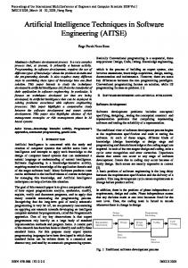
functions from this optimization are shown in Figure 19. It is easy to see that the optimized membership functions differ significantly from the originally defined ones.
Fig. 19. Membership functions after optimization.
The implemented algorithm performs a global optimization. Accordingly, the improvements to the overall RMS error was reduced from 15% in the first iteration, to 3% on the second iteration and only 0:5%. on the third one. Further improvements could be obtained by allowing more parameters in the optimization process, at the expense of computational time. VIII.
Conclusion
This paper discussed the use of conventional methods to detect and diagnose faults in induction motors from electrical failures (inter-turn short circuit, phase unbalance and broken bars) beyond the normal operating condition. Prognosis and Diagnosis provides an optimal solution for detecting the various faults and hence improvising the performance of the machine. Its integration with ANDROID/TIZEN will provide access to the remote operation and detection which can be easily adapted in the industrial atmosphere. Further the technology is being developed for relay less operation in fault detection and diagnosis.
23
References [1] P.F. Albrecht, J.C. Appiarius, R.M. McCoy, E.L. Owen, D.K. Sharma, Assessment of the Reliability of Motors in Utility Applications – Updated, IEEE Trans. Energy Convers. vol.: EC-1, issue 1, pp.39-46, 1986. [2] R. Isermann, “Model Based Fault Detection and Diagnosis—Status and Applications,” Annu. Rev. Control, vol. 29, no. 1, pp. 71–85, 2005. [3] M. Arkan, D. Kostic-Perovic, P. J. Unsworth, “Modelling and Simulation of Induction Motors with Inter-Turn Faults for Diagnostics,” Electric Power Systems Research, vol. 75, pp. 57-66, 2005. [4] F. L. Stanislaw, A .H. M. Sadrul Ula, A. M. Trzynadlowski, “Instantanious Power as a Medium for the Signature Analysis of Induction Motors,” IEEE Trans. Ind. Appl., vol. 32, no. 4, pp. 904-909, 1996. [5] G. G. Yen, K. C. Lin, “Wavelet Packet Feature Extraction for Vibration Monitoring,” IEEE Trans. Ind. Electron., vol. 47, no. 3, pp. 650–667, 2000. [6] H. Douglas, P. Pillay, and A.K Ziarani, “A New Algorithm for Transient Motor Current Signature Analysis Using Wavelets,” IEEE Trans. Ind. Appl., vol. 40, no. 5, pp. 1361–1368, 2004. [7] H. Nejjari, M. H. Benbouzid, “Monitoring and Diagnosis of Induction Motors Electrical Faults using a Current Park’s Vector Pattern Learning Approach,” IEEE Trans. Ind. Appl., vol. 36, no. 3, 2000. [8] A Simple Fuzzy Logic Approach for Induction Motors Stator Condition Monitoring by M. Zeraoulia, A. Mamoune, H. Mangel, M.E.H. Benbouzid J. Electrical Systems 1-1 (2005): 15-25 Regular paper [9] Fault Diagnosis in Induction Motor Using Soft Computing Techniques Thesis submitted in partial fulfilment of the requirements for the degree of Master of Technology (Research) In Electrical Engineering by Rudra Narayan Dash [10] Fuzzy Logic based fault detection in induction machines using Lab view R.SaravanaKumar, K.Vinoth Kumar, Dr. K.K.Ray in IJCSNS International Journal of Computer Science and Network Security, VOL.9 No.9, September 2009
24
[11] Jover Rodríguez, P., Arkkio, A., 2008, Detection of Stator Winding Fault in Induction Motor Using Fuzzy Logic, Applied Soft Computing, Vol. 8, No. 2, pp. 11121120. [12] Aderiano m. Da silva, b.s. on Induction motor Fault diagnostic and monitoring methods, A thesis submitted to the faculty Of the graduate school, Marquette university, In partial fulfillment of The requirements for The degree of Master of electrical and computer engineering Milwaukee, Wisconsin [13] Aderiano M. Da Silva, Member, IEEE, Richard J. Povinelli, Senior Member, IEEE, and Nabeel A. O. Demerdash, Fellow, IEEE on Induction Machine Broken Bar and Stator Short-Circuit Fault Diagnostics Based on ThreePhase Stator Current Envelopes in IEEE transactions on industrial electronics, vol. 55, no. 3, march 2008 [14] Fatiha Zidani, Demba Diallo, Senior Member, IEEE, Mohamed El Hachemi Benbouzid, and Rachid Naït-Saïd on A Fuzzy-Based Approach for the Diagnosis of Fault Modes in a Voltage-Fed PWM Inverter Induction Motor Drive in IEEE transactions on industrial electronics, vol. 55, no. 2, february 2008 [15] Millind S. Patil, Amir M. Shaikh, Ravindra R. Mudholkar on Motor Health Detection using Fuzzy Logic in International Journal of Engineering Research and Development e-ISSN: 2278-067X, p-ISSN: 2278-800X, www.ijerd.com Volume 3, Issue 9 (September 2012), PP. 73-83 [16] Arfat Siddique, Member, IEEE, GXYadava and Bhim Singh. Review on Applications of Artificial Intelligence Techniques for Induction Machine Stator Fault Diagnostics [17] Pablo Cingolani 1, Jes ´us Alcal´a-Fdez jFuzzyLogic: a Java Library to Design Fuzzy Logic Controllers According to the Standard for Fuzzy Control Programming In International Journal of Computational Intelligence Systems, Vol. 6, Supplement 1 (2013), 61-75 [18] Online References from: (i)TIZENhttps://developer.tizen.org/devguide/2.3.0/org.tizen.gettingstarted/html /tizen_overview/tizen_overview.htm (ii)https://developer.tizen.org/devguide/2.2.1/org.tizen.web.appprogramming/ht mltutorials/tizen_tutorial/creating_composite_filter.htm (iii)https://developer.tizen.org/devguide/2.2.1/org.tizen.web.appprogramming/ht ml tutorials/tizen_tutorial/creating_attribute_range_ ilters.htm (iv)https://code.google.com/p/fuzzylite/wiki/fuzzylite3x (v)http://jfuzzylogic.sourceforge.net/html/manual.html