ICWMC 2011 : The Seventh International Conference on Wireless and Mobile Communications
Angular CMA: A modified Constant Modulus Algorithm providing steering angle updates Koen C. H. Blom, Marcel D. van de Burgwal, Kenneth C. Rovers, Andr´e B. J. Kokkeler and Gerard J. M. Smit Dep. of Electrical Engineering, Mathematics and Computer Science University of Twente, P.O. Box 217, 7500 AE, Enschede, The Netherlands Email:
[email protected],
[email protected],
[email protected],
[email protected],
[email protected]
Abstract—Conventional blind beamforming algorithms have no direct notion of the physical Direction of Arrival angle of an impinging signal. These blind adaptive algorithms operate by adjusting the complex steering vector in the case of changing signal conditions and directions. This paper presents Angular CMA, a blind beamforming method that calculates steering angle updates (instead of weight vector updates) to keep track of the desired signal. Angular CMA and its respective steering angle updates are particularly useful in the context of mixed-signal hierarchical arrays as means to find and distribute steering parameters. Simulations of Angular CMA show promising convergence behaviour, while having a lower complexity than alternative methods (e.g., MUSIC). Keywords-blind beamforming; CMA; hierarchical arrays
I. I NTRODUCTION Adaptive beamforming algorithms operate by adjusting the beamformer steering vector in the case of changing signal (conditions and) directions. A subclass of these adaptive algorithms is the subclass of the blind beamforming algorithms. These algorithms use structural properties of the desired signal as a reference to calculate appropriate weight adjustments and have no direct notion of the physical Direction of Arrival (DOA) angle of this signal [1]. Existing blind beamforming algorithms operate on all antenna inputs and update the entire complex steering vector. However, in mixed-signal hierarchical arrays this situation is different. Here, beamforming is performed on multiple levels, partly analog and partly digital. Spatial interference is already being suppressed by the analog beamformers before the signal is being digitized [2]. These analog beamformers decrease the dynamic range of the input signals to the Analog-to-Digital Converters (ADCs), therefore requirements for the ADCs are lowered. The remaining interference can be further suppressed or nulled in the digital domain. Within this layered architecture, a classical digital blind beamforming algorithm has merely the results of the analog beamformers available and can only update its own digital steering parameters. However, for deterministic steering of Supported through STW projects: CMOS Beamforming (07620) and SeaSTAR (10552).
Copyright (c) IARIA, 2011.
ISBN: 978-1-61208-140-3
the complete hierarchical system a novel adaptive algorithm is required that can efficiently track a desired signal and distribute steering parameters throughout the complete array. This paper presents a modified blind beamforming algorithm that senses the presence of mispointing and calculates the required steering angle updates (instead of weight vector updates) to keep track of the desired signal. The desired steering angle can now be calculated at the digital level of the layered architecture and thereafter distributed to both the analog and digital beamformers. This approach is based on the conventional Constant Modulus Algorithm (CMA) algorithm, but since it operates on the steering angle instead of the steering vector, it is called Angular CMA. Both CMA and Angular CMA use the Constant Modulus (CM) property of the received signal as a reference to calculate appropriate weight adjustments. The search space of CMA constitutes of all complex weights that make up the steering vector [3]. However, in Angular CMA this search space is reduced to a single steering angle.
~x y Beamformer
w ~ Linear Phase Taper
Analog beamformer, localisation algorithm ...
θ Angular CMA
Adaptive beamformer
Figure 1.
Angular CMA based adaptive beamformer.
This work describes Angular CMA in the context of a simplified (non-hierarchical) array architecture that is shown in Figure 1. Herein, Angular CMA operates on narrowband signals received by an N -element Uniform Linear Array
42
ICWMC 2011 : The Seventh International Conference on Wireless and Mobile Communications
(ULA). The output of the ULA at each sample instant is a vector of N quadrature baseband samples and is indicated by ~x. A changing DOA angle affects the antenna data ~x. Traditional CMA compensates for these effects by updating the steering vector w ~ directly. Angular CMA first calculates the desired steering angle θ and uses a Linear Phase Taper (LPT) to find w. ~ As shown in Figure 1, the steering angle θ can also be used for steering analog beamformers and for applications that require a notion of the physical DOA angle. A basic classification of adaptive array algorithms can be found in Section II, followed by a concise description of CMA in Section III. Thereafter, the derivation of Angular CMA is given in Section IV. Section V compares simulation results of Angular CMA and traditional CMA with as main point of comparison their convergence behaviour. The computational complexity of Angular CMA is discussed in Section VI. Advantages and disadvantages of Angular CMA are discussed in Section VII. Finally, a short overview of the most significant results and future work is given in Section VIII. II. R ELATED W ORK Adaptive beamforming algorithms can be categorized in three classes: temporal reference, spatial reference and blind beamforming algorithms [1]. Temporal reference algorithms use training sequences in the received signal to calculate adjustments for the array steering vector. These algorithms can only be used in case training sequences are available and therefore their use is limited. We aim for a more generic solution, e.g., to track Digital Video Broadcasting Satellite (DVB-S) signals. Spatial reference algorithms are based on the spatial correlation characteristics of the received antenna signals. A major application of these algorithms is DOA angle determination of the impinging signals. Some methods in this class are: Multiple Signal Classification (MUSIC), Estimation of Signal Parameters by Rotational Invariance Techniques (ESPRIT) and Maximum Likelihood (ML) based techniques [4][5][6]. Typically spatial reference algorithms have a high computational complexity. Blind beamforming algorithms, also known as blind deconvolution algorithms, perform adaptive inverse filtering in an unsupervised manner [7]. In this paper the CM property of the received signal is exploited to perform blind deconvolution. Originally, this idea was proposed by Godard [8]. Independently of Godard, a special case of this idea was published by Treichler and Agee [9]. They named their algorithm the Constant Modulus Algorithm (CMA). The algorithms from Godard and from Treichler and Agee, minimize a nonconvex cost function by adapting complex weights. In contrast to adapting all complex weights this work introduces a special case of CMA that directly acts on the array steering angle.
Copyright (c) IARIA, 2011.
ISBN: 978-1-61208-140-3
III. C ONSTANT M ODULUS A LGORITHM (CMA) CMA penalizes deviation of the beamformer output from a constant modulus. The cost function J is defined as the expected deviation of the squared modulus beamformer output y with respect to the constant R2 [7]: 2
J = E{(|y[k]| − R2 )2 }
(1)
Herein, k is an index for different sampling instants and ‘E’ represents expectation. R2 is chosen such that the gradient of J is zero when minimum costs are reached and is written as: 4 E[|x[k]| ] (2) R2 = 2 E[|x[k]| ] For an ideal normalized CM beamformer output the constant R2 is equal to one. Therefore, in our further analysis of CMA and in the derivation of Angular CMA the constant R2 is assumed to be one. The cost function J is illustrated in Figure 2. Minimum costs are reached when the beamformer output y has unit modulus. The beamformer output can be expressed as w ~ H ~x. The aim of CMA is to minimize J by altering w. ~ A stochastic gradient descent technique can be used to attain this goal. The gradient of J with respect to w ~ is found as follows: n o 2 J = E (|y| − 1)2 (3) n o 2 2 ∇w~ J = 2 · E (|y| − 1) · ∇w~ ( w ~ H ~x − 1) (4) n o 2 ∇w~ J = 2 · E (|y| − 1) · ∇w~ (w ~ H ~x~xH w ~ − 1) (5) Continue using the fact that ~x~xH is a Hermitian matrix and ∇w~ w ~ H Aw ~ = 2Aw ~ holds for every Hermitian matrix A [10]: o n 2 ∇w~ J = 4 · E (|y| − 1) · ~x~xH w ~ (6) n o 2 ∇w~ J = 4 · E (|y| − 1) · y ∗ ~x (7) Based on Equation 7 the minimizer for the stochastic gradient descent version of CMA is found: 2
w[k ~ + 1] = w[k] ~ − µ · (|y[k]| − 1) · y[k]∗ ~x[k]
(8)
Herein, µ absorbs the factor 4 and determines the convergence speed.
J
1 0.8 0.6 0.4 0.2 0
1 0.5 0
-1 -0.5
-0.5 0 R{y}
Figure 2.
I{y}
-1
0.5 1
Surface plot of the CMA cost function (R2 = 1).
43
ICWMC 2011 : The Seventh International Conference on Wireless and Mobile Communications
IV. A NGULAR CMA
1
0.8
0.6 Costs J
The previous section mentions that the CMA minimizer is found by expressing y in Equation 3 as w ~ H ~x, followed by derivation of the gradient of J with respect to w. ~ Angular CMA is constructed by expressing y in Equation 3 as w(θ) ~ H ~x, followed by derivation of J with respect to θ. The term w(θ) ~ is called a Linear Phase Taper (LPT) and is explained in the next section. Successively, the errorperformance surface and the derivation of Angular-CMA minimizer are discussed.
0.4
0.2 N =8 N =4 N =2
0 -80 -60 -40 -20
A. Linear Phase Taper (LPT) A LPT is a linear phase variation across the array aperture, which produces a beamshift of the main beam without any change in sidelobe structure [11]. Figure 1 shows that given a desired steering angle θ the LPT calculates the required output steering vector w. ~ If one of the outer array element acts as a phase reference then the LPT for an N -element ULA can be written as: w(θ) ~ = eφ(θ)·~n ,
~n = [0 . . . (N − 1)]T
(9)
With φ(θ) defined as: j2π · d sin(θ) (10) λ Herein, d represents the spacing of the antenna elements and λ the wavelength of the desired signal. φ(θ) =
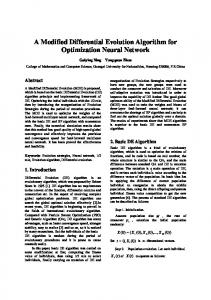
B. Error-performance surface The dependence of the cost function J on the weights w ~ is called the error-performance surface [7]. For CMA this dependence is an (N + 1)-dimensional surface with N degrees of freedom, where N is the number of antenna elements. In the case of more than two degrees of freedom such a surface is hard to visualize. The error-performance surface of Angular CMA is twodimensional with only one degree of freedom (the steering angle θ). Therefore, its error-performance surface can be visualized using a two-dimensional plot. Mathematically, this surface can be written as: j2π·d sin(θ) 2 2 ·~ n H λ J(θ) = ( w(θ) ~ H ~x − 1)2 = ( (e ) ~x − 1)2 (11) Herein, the expectation operator ‘E’ is dropped because noiseless antenna data is taken for plotting. Figure 3 shows the error-performance surface of Angular CMA for a λ2 element spacing and signals arriving from broadside (θ = 0). The surface is drawn for a two-, fourand eight-element array. For all three array configurations holds that a steering angle θ of zero degrees has the lowest costs. This behaviour is expected because the signals arrive from the broadside direction. Note that, based on Figure 3 (and Equation 11), the errorperformance surface of Angular CMA has the appearance of
Copyright (c) IARIA, 2011.
ISBN: 978-1-61208-140-3
0
20
40
60
80
Steering angle (θ)
Figure 3.
Error-performance surface of Angular CMA.
a vertically flipped beam pattern. An increase in the number of antenna elements results in a smaller angular range where convergence to the global minimum can be guaranteed. This region corresponds to the Inter-Null Beamwidth (INBW) of an array pattern. The INBW is defined as the difference between the nearest two nulls around a given angle [1]. If this given angle is the center of the main beam then the INBW can be expressed as follows: INBW = 2 sin−1 (λ/(dN ))
(12)
Thus, for an eight element array with λ2 element spacing Angular CMA has a convergence region width of 2 sin−1 ( 14 ) ≈ 29◦ . DOA estimation algorithms, such as MUSIC, can be used to provide an initial steering angle for Angular CMA [4]. The accuracy of this estimate should be within the angular range of Angular CMA that provides convergence to the global minimum. C. Derivation of the minimizer The minimizer of Angular CMA can be found by expressing y in Equation 3 as w(θ) ~ H ~x = (eφ(θ)·~n )H ~x. Thereafter, the first derivative of J with respect to θ is determined: 2 J(θ) = E{( (eφ(θ)·~n )H ~x − 1)2 } (13) ∂ 2 J = E{2(|y| − 1) · ∂θ ∂ 2 J = 2E{(|y| − 1) · ∂θ
∂ ((eφ·~n )H ~x~xH eφ·~n − 1)} (14) ∂θ ∂ H φ·~n −φ·~n T (~x e (e ) ~x − 1)} (15) ∂θ
Continue by writing eφ·~n (e−φ·~n )T as matrix B: ∂ H ∂ 2 J = 2E{(|y| − 1) · (~x B~x − 1)} ∂θ ∂θ 1 · · · eφ·(n0 −nN −1 ) .. .. B= . 1 . φ·(nN −1 −n0 ) e ... 1
(16)
(17)
44
ICWMC 2011 : The Seventh International Conference on Wireless and Mobile Communications
The derivative of J with respect to θ is written in Equation 18. Note that φ is dependent on θ.
(nN −1
∂ ∂θ B(θ)
··· 0 ...
-6
0.6
0 (n0 −nN −1 )φ
(n0 − nN −1 )φ e . . . 0
-8 0.4
-10 -12
0.2 -14
(19) 0
Herein, φ (θ) is
∂ ∂θ φ(θ):
0 0
j2π · d cos(θ) (20) λ The use of an instantaneous gradient estimate of Equation 18 yields the following algorithm:
-16 100 200 300 400 500 600 700 800 900 1000 Sample
φ0 (θ) =
Herein, the value 2 is absorbed in the convergence factor µ. V. S IMULATION R ESULTS In this section, the convergence of Angular CMA is examined by looking at the cost and Mean Square Error (MSE) behaviour during adaptation. Simulations are performed for both Angular CMA and traditional CMA to provide means for comparison. For simulation the adaptive beamformer architecture presented in Figure 1 is implemented. An eight element ULA with λ2 element spacing is assumed. The baseband samples are Quadrature Phase-Shift Keying (QPSK) modulated and have a Signal-to-Noise Ratio (SNR) of 16 dB. Note that QPSK signals possess the CM property, which is required by both Angular CMA and CMA.
Figure 4.
Convergence behaviour of Angular CMA (µ = 5 · 10−2 ).
plotted in Figure 5 using the same simulation parameters as in Figure 4. Clearly, CMA takes more samples to convergence than Angular CMA. The rapid convergence of Angular CMA is caused by its drastic search space reduction from N complex weights to one real value. A theoretical analysis on the convergence properties of Angular CMA and choosing the factor µ is beyond the scope of this paper. 1
CMA costs
0.8
0.6 Costs J
2
θ[k + 1] = θ[k] − µ(|y[k]| − 1) · (~x[k]H B 0 (θ[k])~x[k]) (21)
0.4
0.2
A. Learning curve
0
The performance of an adaptive algorithm is often studied by looking at the ‘learning curve’ of the cost function J. As mentioned in the theoretical analysis, an eight element array running Angular CMA should be able to converge to the correct array steering angle if the initial steering angle stays within the 29◦ wide convergence region. Validity of this statement is checked in simulation. This is done by setting the DOA angle to broadside (0◦ ), while having the initial steering angle set to one of the extremes of the convergence ◦ region (0◦ ± 29 2 ≈ ±14 ). Figure 4 shows that Angular CMA rapidly convergences to the correct steering angle and consequently minimizes the costs. The previous simulation uses a convergence factor µ of 5 · 10−2 , in contrast to 5 · 10−3 typically used for CMA. Angular CMA is still robust with a large convergence factor, because the gradient descent ensures global minimization if the steering angle is initially within the convergence region. In an attempt to compare the convergence properties of Angular CMA and CMA, the cost behaviour of CMA is
Copyright (c) IARIA, 2011.
-2 -4
(18)
can be written as:
0 . . . − n0 )φ0 e(nN −1 −n0 )φ
0
Steering angle θ (degrees)
Where B 0 (θ) =
Angular CMA costs Steering angle
0.8
Costs J
∂ 2 J = 2E{(|y| − 1) · (~xH B 0 (θ)~x)} ∂θ
1
ISBN: 978-1-61208-140-3
0
100 200 300 400 500 600 700 800 900 1000 Sample
Figure 5.
Convergence behaviour of CMA (µ = 5 · 10−2 ).
B. Mean Square Error (MSE) A common method to evaluate an equalizer is to determine the MSE of its output signal (predetection error). Both CMA and Angular CMA do not correct phase offsets in the beamformer output signal. This phase blindness should not affect the MSE of their output signals, therefore the following method is used to calculate the MSE: 2 ∆ MSE = min E{ w[k] ~ H ~x[k] − ejα s[k] } (22) α
Herein, s[k] represents the (noiseless) transmitted signal at sample instant k. This unconventional method of MSE calculation is introduced by Treichler and Agee [9]. Estimates for the MSE of the CMA and Angular CMA outputs can be seen in Figure 6. The estimates are based on
45
ICWMC 2011 : The Seventh International Conference on Wireless and Mobile Communications
0
Angular CMA CMA
-5
MSE (dB)
-10 -15 -20 -25 -30 -35 -40 0
400
800
1200
1600
2000
Sample
Figure 6.
MSE comparison (µ = 5 · 10−2 ).
the same scenario as in the previous simulation. The results are smoothed by a moving average filter to reveal trends. Figure 6 reveals that the MSE for both algorithms drop, as expected, on the same time scale as the costs in Figure 4 and Figure 5. Interestingly, the MSE level of Angular CMA after convergence is below that of CMA. VI. C OMPLEXITY A NALYSIS A short analysis on the complexity of Angular CMA is given to assess scalability and implementability. The computational complexity of Angular CMA is compared with that of CMA and MUSIC. MUSIC is included in the comparison because it provides DOA estimates of all impinging signals. Therefore, repeated execution of MUSIC could be used for tracking. However, this requires a method to identify the DOA of the desired signal out of all angles found by MUSIC. The computational order of complexity of the algorithms is determined by counting the number of complex MultiplyAccumulate (MAC) operations. The complexity of Angular CMA is determined based on Equation 21. Calculation of matrix B 0 (θ[k]) is kept out of the complexity analysis since we expect that, by exploiting its Hermitian symmetry, this can be done very efficiently. Therefore, not taken calculation of B 0 (θ[k]) into account, the order of Angular CMA is dominated by the matrix-vector multiplication B 0 (θ[k])~x[k] and is for that reason Θ(N 2 ). Herein, N is the number of antenna elements. The stochastic gradient descent version of CMA, often referred to as Stochastic Gradient CMA (SG-CMA), is of order Θ(N ) [12]. MUSIC is computationally much more expensive with a complexity of order Θ(N 3 ) [13]. Thus, the complexity of Angular CMA is in between that of CMA and MUSIC.
implications. The main advantages and disadvantages of Angular CMA are discussed in this section. Traditional CMA is attractive for application in array architectures because of its insensitivity to array imperfections [3], low complexity and because training sequences are not required. Since Angular CMA controls steering by distributing only a single steering parameter, it can not correct for small array imperfections. Despite the fact that a single steering parameter cannot cope with array imperfections, it is advantageous in systems where the dynamics of the source can be expressed by a Linear Time-Invariant (LTI) system. When dealing with such a system the notion of a physical DOA angle can be input to a state estimation technique, such as the Kalman filter [7]. Erratic behaviour in the steering angle can then be corrected and most likely the update rate of Angular CMA can be further reduced. CMA minimizes the effect of interferers by placing nulls at their respective DOA angles. Angular CMA is restricted to array responses that can be generated by a LPT. Therefore, it cannot place nulls as CMA can. Nonetheless, after correct convergence of Angular CMA, exact numbers on the suppression of other directions can be given. These numbers are found by evaluating the LPT array response based on the steering angle output from Angular CMA. In hierarchical arrays exact directivity properties for each array level ease design choices for the aggregate structure. VIII. C ONCLUSION AND F UTURE W ORK Angular CMA, a modified version of CMA, is presented in this work. The algorithm calculates steering angle updates to keep track of the desired signal. Within the context of hierarchical arrays it provides a means for efficiently tracking and distributing steering parameters. The cost behaviour of Angular CMA is compared with that of CMA. Angular CMA provides faster convergence and a lower MSE floor. The complexity of the algorithm is of order Θ(N 2 ). Compared to the complexity of other methods for steering angle calculation (e.g., MUSIC), our method is favorable. Angular CMA is investigated within the context of a simplified non-hierarchical beamformer. Further research should look at the applicability of the algorithm in a hierarchical setup in simulation and in practice. The algorithm cannot correct for small array imperfections. Whether these influence the convergence of Angular CMA should be examined. Our current work is focused at extending the angular convergence region by exploiting other optimization techniques and incorporating other cost functions to deal with phase blindness [14].
VII. D ISCUSSION
ACKNOWLEDGMENTS
The reduction of the CMA search space from N complex weights to a single steering angle has certain important
The authors would like to thank Marco Gerards for assistance on the mathematics.
Copyright (c) IARIA, 2011.
ISBN: 978-1-61208-140-3
46
ICWMC 2011 : The Seventh International Conference on Wireless and Mobile Communications
R EFERENCES [1] B. Allen and M. Ghavami, Adaptive Array Systems, Fundamentals and Applications. John Wiley & Sons, 2005. [2] B. Smolders and G. Hampson, “Deterministic RF nulling in phased arrays for the next generation of radio telescopes,” in IEEE Transactions on Antennas and Propagation, 1999. [3] R. Gooch and J. Lundell, “The CM array: An adaptive beamformer for constant modulus signals,” in Acoustics, Speech, and Signal Processing, IEEE International Conference on ICASSP ’86., vol. 11, Apr 1986, pp. 2523–2526. [4] R. Schmidt, “Multiple emitter location and signal parameter estimation,” Antennas and Propagation, IEEE Transactions on, vol. 34, no. 3, pp. 276–280, Mar 1986. [5] A. Paulraj, R. Roy, and T. Kailath, “A subspace rotation approach to signal parameter estimation,” Proceedings of the IEEE, vol. 74, no. 7, pp. 1044–1046, 1986. [6] I. Ziskind and M. Wax, “Maximum likelihood localization of multiple sources by alternating projection,” Acoustics, Speech and Signal Processing, IEEE Transactions on, vol. 36, no. 10, pp. 1553–1560, Oct. 1988. [7] S. Haykin, Adaptive Filter Theory, 4th ed. 2001.
Copyright (c) IARIA, 2011.
Prentice Hall,
ISBN: 978-1-61208-140-3
[8] D. Godard, “Self-recovering equalization and carrier tracking in two-dimensional data communication systems,” Communications, IEEE Transactions on, vol. 28, no. 11, pp. 1867– 1875, Nov. 1980. [9] J. Treichler and B. Agee, “A new approach to multipath correction of constant modulus signals,” Acoustics, Speech and Signal Processing, IEEE Transactions on, vol. 31, no. 2, pp. 459–472, Apr 1983. [10] P. Nelson and S. Elliott, Active Control of Sound. Academic Press, 1993. [11] A. Rudge, The Handbook of Antenna Design: Volume 1, K. Milne, A. Olver, and P. Knight, Eds. Institution of Electrical Engineers, 1982. [12] V. Zarzoso and P. Comon, “Blind channel equalization with algebraic optimal step size,” in in Proc. XIII Eur. Signal Process. Conf, 2005. [13] M. Rubsamen and A. Gershman, “Direction-of-arrival estimation for nonuniform sensor arrays: From manifold separation to fourier domain music methods,” Signal Processing, IEEE Transactions on, vol. 57, no. 2, pp. 588–599, 2009. [14] K. Blom, M. van de Burgwal, K. Rovers, A. Kokkeler, and G. Smit, “DVB-S signal tracking techniques for mobile phased arrays,” in Vehicular Technology Conference Fall (VTC 2010-Fall), 2010 IEEE 72nd, 2010, pp. 1–5.
47