Angular momentum of multimode and polarization patterns Roberta Zambrini1,∗ and Stephen M. Barnett2 1
IFISC Institute for Cross-Disciplinary Physics and Complex Systems (UIB-CSIC), Palma de Mallorca 07122 (Spain) 2 Department of Physics, SUPA, University of Strathclyde, Glasgow G4 0NG (UK) ∗ Corresponding author:
[email protected]
Abstract: We study the mechanical properties of a broad class of multimode and polarization light patterns, resulting from the interference and superposition of waves in helical modes. General local and global properties of energy and angular momentum (AM) are identified, in order to define the conditions to optimize the AM with increasing beam complexity. We show the possibility to engineer independently the local densities of optical AM and energy, opening the possibility of an experimental demonstration of their respective effects in light-matter interaction. Multimode Laguerre-Gaussian beams also allows us to tailor the local spin AM through the Gouy phase. © 2007 Optical Society of America OCIS codes: (260.2110) Physical optics: Electromagnetic optics; (350.4855) Other areas of optics: Optical tweezers or optical manipulation
References and links 1. R.A. Beth, ”Mechanical Detection and Measurement of the Angular Momentum of Light,” Phys. Rev. 50, 115 – 125 (1936) 2. L. Allen, M.W. Beijersbergen, R.J.C. Spreeuw, J.P. Woerdman,“Orbital angular momentum of light and the transformation of Laguerre-Gaussian laser modes,” Phys. Rev. A 45, 8185 – 8189 (1992) 3. D. McGloin and K. Dholakia, ”Bessel beams: diffraction in a new light,” Contemp. Phys. 46, 15 – 28 (2005) 4. L. Allen, S.M. Barnett, M.J. Padgett, Optical angular momentum (Institute of Physics Publishing, Bristol, 2003) 5. F. Tamburini, G. Anzolin, G. Umbriaco, A. Bianchini and C. Barbieri “Overcoming the Rayleigh Criterion Limit with Optical Vortices,” Phys. Rev. Lett., 97, 163903 (2006); W. Wang, T. Yokozeki, R. Ishijima, A. Wada, Y. Miyamoto, M. Takeda, and S. G. Hanson, ”Optical vortex metrology for nanometric speckle displacement measurement,” Opt. Express 14, 120 – 127 (2006) 6. C. Maurer, A Jesacher, S. F¨urhapter, S. Bernet and M. Ritsch-Marte, ”Tailoring of arbitrary optical vector beams,” New J. Phys. 9, 78 (2007) and references therein. 7. D. G. Grier, ”A revolution in optical manipulation,” Nature 424, 810 – 816 (2003); A. Jesacher, S. F¨rhapter, S. Bernet, and M. Ritsch-Marte, ”Size selective trapping with optical cogwheel tweezers,” Opt. Express 12, 4129 – 4135 (2004); S. H. Tao, X-C. Yuan, J. Lin, X. Peng, H. B. Niu, “Fractional optical vortex beam induced rotation of particles,” Opt. Express 13, 7726 – 7631 (2005) 8. S. H. Tao, X. C. Yuan, J. Lin, and R. E. Burge, ”Residue orbital angular momentum in interferenced double vortex beams with unequal topological charges,” Opt. Express 14, 535 – 541 (2006) 9. C. H. J. Schmitz, K. Uhrig, J. P. Spatz, and J. E. Curtis, ”Tuning the orbital angular momentum in optical vortex beams,” Opt. Express 14, 6604 – 6612 (2006) ¨ 10. S. Franke-Arnold, J. Leach, M. J. Padgett, V. E. Lembessis, D. Ellinas, A. J. Wright, J. M. Girkin, P. Ohberg and A. S. Arnold, “Optical ferris wheel for ultracold atoms,” Opt. Express 15, 8619 – 8625 (2007) 11. R. Di Leonardo, J. Leach, H. Mushfique, J. M. Cooper, G. Ruocco and M. J. Padgett, “Multiport holographic velocimetry in microfluidic systems,” Phys. Rev. Lett. 96, 134502 (2006)
#87436 - $15.00 USD
(C) 2007 OSA
Received 12 Sep 2007; revised 9 Oct 2007; accepted 9 Oct 2007; published 2 Nov 2007
12 November 2007 / Vol. 15, No. 23 / OPTICS EXPRESS 15214
12. G. Molina-Terriza, J.P. Torres and L. Torner, ”Twisted photons,” Nature Phys. 3, 305 – 310 (2007) and refernces therein. 13. W. Nasalski, “Polarization versus spatial characteristics of optical beams at a planar isotropic interface,” Phys. Rev. E 74, 056613 (2006) 14. K. O’Holleran, M. J. Padgett, and M. R. Dennis, ”Topology of optical vortex lines formed by the interference of three, four, and five plane waves,” Opt. Express 14, 3039-3044 (2006) 15. J. Courtial, R. Zambrini, M. R. Dennis and M. Vasnetsov, “Angular momentum of optical vortex arrays,” Opt. Express 14, 938 (2006) 16. S. Vyas and P. Senthilkumaran, “Interferometric optical vortex array generator,” Applied Optics 46, 2893 – 2898 (2007) 17. J. Masajada, A. Popiolek-Masajada, and M. Leniec, ”Creation of vortex lattices by a wavefront division,” Opt. Express 15, 5196 – 5207 (2007) 18. S.M. Barnett and R. Zambrini, “Orbital angular momentum of light” in Quantum Imaging, Mikhail I. Kolobov Ed. (Springer-Verlag New York, 2006) and references in Section 12.6 19. M. Hoyuelos, P. Colet, M. San Miguel, D. Walgraef, “Polarization patterns in Kerr media,” Phys. Rev. E 58, 2992 – 3007 (1998); G.-L. Oppo, A. J. Scroggie, and W. J. Firth,”Characterization, dynamics and stabilization of diffractive domain walls and dark ring cavity solitons in parametric oscillators,” Phys. Rev. E 63, 066209 (2001) 20. E. Miyai, K. Sakai, T. Okano, W. Kunishi, D. Ohnishi, S. Noda, “Lasers producing tailored beams,” Nature 441, 946 (2006) 21. D. Boiko, G. Guerrero, and E. Kapon, ”Polarization Bloch waves in photonic crystals based on vertical cavity surface emitting laser arrays,” Opt. Express 12, 2597 – 2602 (2004) 22. A.Ferrando, M. Zacar´es, and M.-A. Garc´ıa-March, “Vorticity cutoff in Nonlinear Photonic Crystals,” Phys. Rev. Lett. 95, 043901 (2005). 23. R. Zambrini and S.M. Barnett, “ Quasi-Intrinsic Angular Momentum and the Measurement of Its Spectrum,” Phys. Rev. Lett. 96, 113901 (2006) 24. M. S. Soskin, V. N. Gorshkov, M. V. Vasnetsov, J. T. Malos, and N. R. Heckenberg, ”Topological charge and angular momentum of light beams carrying optical vortices,” Phys. Rev. A 56, 4064 – 4074 (1997) 25. A.T. O’Neil, I. MacVicar, L. Allen, M.J. Padgett, “Intrinsic and extrinsic nature of the orbital angular momentum of a light beam,” Phys. Rev. Lett. 88, 053601 (2002). 26. R. Zambrini and S. M. Barnett, “Local transfer of angular momentum to matter,” J. Mod. Opt. 52, 1045 – 1052 (2005). 27. R. Zambrini, L. C. Thomson, S. M. Barnett, M. Padgett, “Angular momentum paradox in a vortex core,” J. Mod. Opt., 52, 1135 – 1144 (2005). 28. S. M. Barnett, “Optical angular-momentum flux”, J. Opt. B: Quantum Semiclass. Opt. 4, S7 – S16 (2002) 29. L. Allen and M. J. Padgett, “The Poynting vector in Laguerre-Gaussian beams and the interpretation of angular momentum density,” Opt. Commun. 184, 67 – 71 (2000) 30. M. Born and E. Wolf, Principles of Optics (Pergamon, Oxford, 1975). 31. A. Siegman, Lasers (University Science Books, Sausalito, 1986) 32. K. T. Gahagan, G.A. Swartzlander, “Optical vortex trapping of particles,” Opt. Lett. 21, 827 – 829 (1996) 33. The same periodicity was found for the energy and orbital AM of an interference field, because the imaginary part of the phase sensitive term UV∗ appears in the spin AM of a superposition field while the real part appears in the orbital AM of the interference one. 34. J. F. Nye, Natural focusing and the fine structure of light (Institute of Physics Publishing, Bristol, 1999)
1. Introduction Spin and orbital angular momenta of light have been observed in many experiments via the transfer of these mechanical quantities to matter. The results have been in agreement with theoretical predictions for easily accessible beams characterized by circular polarization and helical phase profiles, including Laguerre-Gaussian (LG) and Bessel beams [1, 2, 3, 4]. Recently, more complex beams have been subject of investigations because of their applications in imaging [5, 6], tweezers [7, 8, 9], atomic trapping [10], microfluidic [11], and quantum information [12]. These multimode beams and polarization patterns are composed by different helical components with azimuthal phase dependence exp(i!φ ) and can be generated with spatial light modulators, or other linear optical elements [4, 6, 13, 14, 15, 16, 17]. Moreover, these beams can also occur as the result of the nonlinear processes of wave mixing [4, 18], as the result of spontaneous pattern formation [19] or in specially engineered lasers and photonic crystals [20, 21, 22]. A device to measure the spectrum of helical components of generic multimode #87436 - $15.00 USD
(C) 2007 OSA
Received 12 Sep 2007; revised 9 Oct 2007; accepted 9 Oct 2007; published 2 Nov 2007
12 November 2007 / Vol. 15, No. 23 / OPTICS EXPRESS 15215
beams has been proposed in [23]. An interesting way to increase the complexity of Gaussian light beams is to consider the case of multimode beams, resulting from the inter f erence of an increasing number of modes. Some recent work reports on the effects of interfering LG modes in the context of singular optics looking, for example, at the topology of the singularities along the propagation beam direction [24] and in relation with optical manipulation [8, 9]. In particular, Ref. [8] shows the possibility to concentrate opposite orbital AM in different circles in the transverse profile of the beam, while Ref. [9] reports on the tuning of the orbital AM by the interference of modes with opposite helicity and different intensities. Both references consider the interference of vortex beams with the same (linear) polarization. In addition to interference, it is also interesting to explore the role of the vectorial character of the electromagnetic field through the analysis of the superposition of orthogonal linearly polarized beams, in the context of AM. With the proper choice of relative phases, interference can be used to obtain LG modes carrying orbital AM starting from two orthogonal HermiteGaussian beams, with vanishing orbital AM [2], while superposition of identical beams that are linearly polarized in orthogonal directions, with vanishing spin AM, gives rise to elliptically polarized light carrying a non-vanishing spin AM and also to radially and azimuthally polarized beams [6]. There is clearly a rapidly increasing number of experiments and theoretical proposals dealing with beams of increasing complexity, both in terms of number of spatial modes and polarization states. Our interest lies in the mechanical properties of these beams, focusing on local and global features of both scalar and vectorial beams obtained, respectively, by interference and superposition (see Eqs. 10, 11). Multimode beams have optical AM features that are profoundly different from those of orbital AM eigenmodes with their helical phase profiles and uniform polarization states. The study of local properties, such as the densities of linear and AM [25, 26, 27], is fundamental for experiments accessing only portions of the beam like tweezers and atoms or ion trapping, as well as any aperture effects introduced by optical elements. We show that increasing the complexity of light beams opens up the possibility to engineer, independently, the local orbital AM and energy densities and we propose an experiment to identify the independent roles of these in optical trapping. A simple way to obtain circles with opposite spin AM is also shown just by exploiting the Gouy phase. We also study global properties of a general class of beams, including the average energy and AM, and we identify the conditions to optimize the amount of AM per photon with increasing beam complexity. In particular, we consider whether it is more efficient to interfere or superpose beams in order to generate orbital and spin AM. 2. Linear and angular momenta and energy Much of the literature on the mechanical properties of light treats beams carrying a uniform polarization. In such cases a scalar wave theory suffices to describe the light and its mechanical properties. It is important to recall, however, the expressions for the linear and AM in the most general case, as a function of arbitrary field components E. The review in this section aims to point out the principal effects arising when multimode polarization patterns are considered. We consider only monocromatic beams with electric field 1 e(x,t) = [E(x)eikz−iω t + c.c] 2
(1)
where E = (Ex , Ey , Ez ) is the complex amplitude, ω the frequency and k = ω /c. We work throughout within the limit of paraxial propagation. The transversality constraint on the electromagnetic field, ∇ · e = 0, fixes the field component in the propagation direction, E z , as a #87436 - $15.00 USD
(C) 2007 OSA
Received 12 Sep 2007; revised 9 Oct 2007; accepted 9 Oct 2007; published 2 Nov 2007
12 November 2007 / Vol. 15, No. 23 / OPTICS EXPRESS 15216
function of E x and Ey . Therefore the mechanical properties of paraxial waves can be expressed as a function only of the transverse field E ⊥ = (Ex , Ey ). The linear momentum density in the direction of propagation is pz (x) =
ε0 (|Ex (x)|2 + |Ey (x)|2 ), 2c
(2)
where, as usual, rapidly oscillating terms are removed by temporal averaging over an optical cycle. We define (spatially) averaged quantities as the integral of the densities over any transverse plane (x, y). The importance of these quantities follows from their immediate relation with fluxes in the paraxial limit [28]. In particular, for paraxial light beams, the average linear ! momentum has its largest component in the propagation direction (P z = dxdypz $ Px,y ). The flux of linear momentum is naturally associated with the energy by Poynting’s theorem, which leads to the expression of the time averaged energy per unit length W =
ε0 2
"
dxdy(|Ex |2 + |Ey |2 ).
(3)
The transverse linear momentum density components p ⊥ = (px , py ) are iε0 [(E j ∂x E ∗j ) − ∂y (Ex∗ Ey ) − c.c.] 4ω iε0 [(E j ∂y E ∗j ) + ∂x (Ex∗ Ey ) − c.c.], 4ω
px (x) = py (x) =
(4)
where we adopt the Einstein summation convention and j = x, y. Even if the average total transverse momentum P ⊥ is negligible with respect to Pz , the local value of the density p ⊥ still has important effects being at the origin of optical AM [29]. Surprisingly Eq. (4) vanishes identically for purely real (or imaginary) vectors E ⊥ suggesting that no transverse momentum p ⊥ can be exerted on the focal plane of a fundamental Gaussian mode, in apparent contradiction with the well-known property of Gaussian light beams to move small objects towards the beam axis. The consistency of Eq. (4) is ensured, however, by the paraxial evolution causing any field purely real in a plane (for instance z = 0) to become complex on propagation. Therefore the transverse momentum p ⊥ would not vanish over an interval |z| < ∆z, with ∆z being the thickness of the trapped object. The average total transverse momentum is P⊥ = −
"
dxdy(ε0 /2ω )Im(E j ∇⊥ E ∗j ),
(5)
with “Im” denoting the imaginary part, and has the form of an “expectation value” of the linear momentum, in the language of the analogy between paraxial optics and Schr¨odinger wavemechanics. It is interesting to compare the transverse momentum of uniformly polarized beams with polarization patterns for vector beams. Uniformly polarized paraxial beams have the form ˆ where α and β are complex constants. These beams have a transverse E⊥ (x) = (α xˆ + β y)u(x), momentum density −(ε 0 /2ω )Im(u∇⊥ u∗ ) that is completely independent of the polarization state of the beam. On the other hand, in the presence of polarization patterns, the linearly polarized components E x,y contribute differently to the linear momentum. As a particular example, a field with vanishing average momentum P ⊥ can be obtained by superposing two orthogonally polarized waves with momenta pointing in opposite directions. This is a first example illustrating how the vectorial character of electromagnetic fields can lead to novel capabilities in optical manipulation.
#87436 - $15.00 USD
(C) 2007 OSA
Received 12 Sep 2007; revised 9 Oct 2007; accepted 9 Oct 2007; published 2 Nov 2007
12 November 2007 / Vol. 15, No. 23 / OPTICS EXPRESS 15217
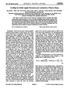
Fig. 1. (a) Intensity distribution of the u20 (x, y, 0) Laguerre-Gaussian mode. The orbital AM density (b) has the same profile of the intensity, the only difference being a scaling factor given by the helicity !. If two orthogonally polarized beams in the same mode but with π /2 dephasing are superposed a circularly polarized wave is obtained. The spin of this wave for u20 is represented in (c) and differs by the intensity distribution only by a scaling given by the degree of polarization. In this case σ = 1. In order to compare with the following pictures regions of the beam in which the intensity is above 80% of its maximum value are highlighted with dashed lines in (b-c).
Comparison of the density of transverse momentum Eq. (4) and the integrand in Eq. (5) reveals a term that does not contribute to the integrated total momentum but is, nevertheless, locally non-vanishing. This vector,
ε0 /2ω (∂y σz (x), −∂x σz (x)),
(6)
is proportional to the transverse components of the curl of the Stokes parameter σ z = −i(Ex∗ Ey − c.c.) (that is the local difference between the left and right circularly polarized intensities) [30], taken in the limit of slow variation of the field envelope along the propagating direction z. Because of its derivative form, this term does not contribute to the average linear momentum P⊥ for any physical beam and it has also been shown that it does not produce directly any mechanical effect [26]. Still, this derivative term is extremely important because it leads to the spin component of optical AM. The density of AM is naturally defined from the linear one as j = x × p and we find the total AM density in the propagation direction in the form jz (x) =
iε0 [E j ∂φ E ∗j + 2Ey∗Ex + ∂x (xEx∗ Ey ) + ∂y (yEx∗ Ey ) − c.c.]. 4ω
(7)
We can readily distinguish different terms contributing to the total AM [4], namely an orbital component !z =
ε0 Im(Ex∗ ∂φ Ex + Ey∗ ∂φ Ey ), 2ω
(8)
ε0 Im(Ex∗ Ey ). ω
(9)
and a spin component sz =
In this case, as for the linear momentum, there is a non-vanishing derivative term in the total density that does not contribute to the average AM and does not have mechanical effects, as discussed in Ref. [26]. We stress that it is necessary (but not sufficient) to have a field E ⊥ with a local circular polarization in some region to obtain a non-vanishing spin AM. Novel fields characterized by azimuthal and radial polarizations therefore do not carry any spin AM even if #87436 - $15.00 USD
(C) 2007 OSA
Received 12 Sep 2007; revised 9 Oct 2007; accepted 9 Oct 2007; published 2 Nov 2007
12 November 2007 / Vol. 15, No. 23 / OPTICS EXPRESS 15218
in general they have a non-vanishing orbital AM. It was already noticed in seminal papers about optical AM that linearly polarized beams in helical (LG) modes have a density of orbital AM (8) that is locally proportional to the energy density [2, 4]. The same is true for the spin AM density if boundary terms are neglected (see Fig. 1). For more complex beams, however, the local mechanical properties can be tailored independently with important consequences in optical manipulation. In particular, for multimode beams, neither the spin nor the orbital AM densities are proportional to the local energy density. It follows also that global properties of these beams are ! different from the single mode case. In the following, we will consider the average L z = dxdy!z resulting from the sum of the orbital AM carried separately by the linearly polarized components E x and Ey and the spin given the spatially averaged Stokes parameter σ z (x). We discuss multimode beams comparing beams obtained either by interference or by superposition. 2.1. Interference and superposition of optical beams At the heart of wave physics is the phenomenon of interference, for which some properties, like the energy, carried by the component waves exhibit local maxima and minima that are not present in the constituent interfering waves. Because of the vectorial character of the electromagnetic field, however, two waves can be combined in a field in such a way that their energy densities add. This occurs when the superposed fields have orthogonal polarizations. In the following we consider the main differences between the mechanical properties in the superposition of two orthogonal linearly polarized beams Es⊥ (x) = (U(x),V (x))
(10)
Ei⊥ (x) = (U(x) + V(x), 0),
(11)
and the linearly polarized field
resulting from the interference of the same fields U and V , but now with parallel polarization. Clearly the interference field (11) does not carry any spin AM but does allow us to include in our analysis the properties of multimode fields, from the sum of different helical modes. On the other hand, the superposition field (10) allows us to identify the relations between different mechanical properties (energies and momenta) of polarization patterns. The polarization pattern (10) carries a total average AM Jzs =
iε0 4ω
"
dxdy[U ∂φ U ∗ + V ∂φ V ∗ + 2V ∗U − c.c.],
(12)
which includes both orbital and spin components, while the interference linearly polarized field Ei carries an (orbital) AM Jzi
iε0 = 4ω
"
dxdy[(U + V )∂φ (U + V )∗ − c.c.].
(13)
Two main differences can be inferred by the comparison of the AM between the interference and superposition fields. The first one is that the local difference in the phases of U and V can give rise to a resulting spin in the polarization pattern E s , and that this occurs despite of the zero spin of the component beams. We stress that in the single mode case [2] the spin AM arises due to a spatially-uniform phase difference between the component beams while for generic Ex and Ey the respective spatial profiles and mode components also play a key role. Locally, non-vanishing spin AM can be induced without global rephasing of the beams (i.e. without using phase plates) by engineering the spatial phase profiles of linearly polarized fields, by use of spatial light modulators, so that the local phases of the beams U and V are mapped into a #87436 - $15.00 USD
(C) 2007 OSA
Received 12 Sep 2007; revised 9 Oct 2007; accepted 9 Oct 2007; published 2 Nov 2007
12 November 2007 / Vol. 15, No. 23 / OPTICS EXPRESS 15219
polarization pattern. If helical modes are considered this gives rise, in a sense, to a transfer of orbital AM into spin AM. It follows that, in general, the local spin and orbital AM densities are two intrinsically correlated properties that cannot be engineered independently in finite regions across the beam profile. In order to produce a polarization pattern it is necessary to introduce a relative phase between the linearly polarized components of the field, but this variation will in general produce a locally non-vanishing orbital AM. The resulting orbital AM also depends on whether we interfere or superpose the two fields. Indeed, the second main observation drawn from Eqs. (12) and (13) is the distinctive property of the superposition of orthogonally polarized waves, allowing not only to add their input energies but also to add their orbital AM. On the other hand, as for the energy, the AM obtained by the interference of two beams is not the sum of their AM. The difference between the orbital angular momenta of E i and Es is Liz − Lsz =
iε0 4ω
"
dxdy[U ∂φ V ∗ + V ∂φ U ∗ − c.c.].
(14)
A trivial way to increase optical AM is to uniformly increase the intensity amplifying E s,i . High powers, however, are often undesirable and, moreover, there are more interesting possibilities. In order to study the efficiency in producing AM, it is meaningful, therefore, to consider the AM per unit of energy (AMPE) or per photon, these quantities being equivalent apart from a factor h¯ ω . This scaling also allows us to distinguish any increase of AM from that arising from the difference in energy for interference and superpositions. For example, in the trivial case V = exp(iθ )U (with θ real constant) the difference (14) is non-vanishing, but this is a simple “side effect” of constructive (θ = 0) or destructive (θ = π ) interference. The orbital AMPE is the same in this case (and independent of θ ) in either superposition or interference. A general and interesting question is whether the interference or the superposition of waves carrying AM produces a beam with the greater AMPE. We start by considering orbital AM, recalling that the spin component is present only for superposition. The natural basis to study AM in paraxial beams is given by LG modes u p! [4, 31]: U(x) = C ∑ a p! u p! (x), p,!
V (x) = C ∑ b p! u p! (x),
(15)
p,!
where C is a real factor with the dimensions of electric field. We can choose the mode amplitudes such that ∑ p,! |a p! |2 = ∑ p,! |b p! |2 = 1 so that C fixes the total energy. We find that the efficiency in producing larger orbital AM is optimized either by interference or superposition depending on the spatial spectral details of the component beams. For example, opposite signs of ! can cancel in the superposition case, while in the case of interference everything is complicated by the possibility that the relative phases of the a and b amplitudes play a roll in determining the total contribution to the AM of each LG mode. This can be seen clearly by considering the orbital AMPE in interference and superposition Liz ∑ p,! |a p! + b p! |2 ! = , Wi ω ∑ p,! |a p! + b p! |2
Lsz ∑ p,! (|a p! |2 + |b p! |2 )! = . Ws ω ∑ p,! |a p! |2 + |b p!|2
(16)
The vectorial character of the electromagnetic field makes it possible to add not only the energies but also the orbital AM through superposition, while orbital AM and energy can be affected either by constructive or destructive interference depending the signs of the factors Re(a p! b∗p! ). It follows that the largest AMPE is obtained by superposing the fields rather than by interfering them when 1
∑ Re(a p! b∗p! )! < 2 ∑ Re(a p! b∗p!) ∑(|a p! |2 + |b p!|2)!. p,!
#87436 - $15.00 USD
(C) 2007 OSA
p,!
(17)
p,!
Received 12 Sep 2007; revised 9 Oct 2007; accepted 9 Oct 2007; published 2 Nov 2007
12 November 2007 / Vol. 15, No. 23 / OPTICS EXPRESS 15220
Equation (17) provides a general criterion with which to establish whether, given two input beams with the same energy but different orbital AM spectra, there is more orbital AMPE in their interference or in their superposition. Naturally the spin AM needs to be included in order to obtain the total AMPE of superposed beams. The averaged total spin AMPE, in terms of the component-mode amplitudes is Szs 1 =− s W ω
∑ Im(a p!b∗p! ).
(18)
p,!
We note that only common mode components in the fields U and V contribute to the average total spin AM. 3. Examples In this section we illustrate, through some examples, both the global and local properties of spin and orbital AM for both the superposition and interference cases as the degree of complexity of the beams is increased. 3.1. Interfering and superposing single Laguerre-Gaussian modes Let us consider two LG modes U(x) = Cu p!1 (x),
V (x) = Cu p!2 (x)
(19)
and consider superposition fields, as in (10), and interference, as in (11). 3.1.1.
Modes with different helicities !1 &= !2
The interference of beams with opposite charges ! 1 = −!2 and different energies was considered in Ref. [9] where the possibility of using the imbalance between the modes to tune the orbital AM on the intense circle was established. A complementary approach was adopted in Ref. [8] to demonstrate the possibility of having rings with opposite orbital AM when ! 1 and !2 have opposite signs and a large difference in the absolute value. Here we consider the case of composing beams with equal energies, different helical indexes (! 1 &= !2 ) (i) focusing on general local and global AM of these beams and (ii) generalizing the analysis by including the vectorial degree of freedom of the electromagnetic field. The superposition of orthogonally polarized LG beams allows us to tailor polarization patterns carrying spin AM. It follows from (17), or from the orthogonality of the modes with ! 1 &= !2 , that the average orbital AM of the superimposed beams (as well as the energy) is the same as that obtained by interference. In particular W i = W s = ε0C2 ,
Liz = Lsz =
ε0C2 (!1 + !2). 2ω
(20)
We note that even if the details of the pattern of both the superimposed and interfering beams depend on the distance z from the beam waist, the average AM are constant at different planes (independent on z). It follows from the orthogonality of the modes, U and V , that the average total spin AM generated by superposition is zero, (Eq. (18)). Finally, modes with different helicities have the same average AM both in superposition and interference, and this is also true of the AM per photon. Even if in this case the global (average) mechanical properties in interference and superposition are the same, important differences appear in their local properties. The orbital AM resulting from constructive interference (a,e) and superposition (b,f) are compared in Fig. 2 and #87436 - $15.00 USD
(C) 2007 OSA
Received 12 Sep 2007; revised 9 Oct 2007; accepted 9 Oct 2007; published 2 Nov 2007
12 November 2007 / Vol. 15, No. 23 / OPTICS EXPRESS 15221
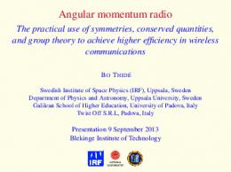
Fig. 2. AM densities obtained by interfering (a,e) constructively and by superposing (b-d,fh) two p = 0 Laguerre-Gaussian modes with !1 = 3, !2 = 2 (a-d) and !1 = 3, !2 = 0 (f-h). Orbital AM (a,b,e,f), spin (c,g) and total(d,h) AM are represented and compared with the intensity highlighted regions (see Fig. 1).
Fig. 3. AM densities as in Fig. 2 in the case of !1 = 7, !2 = −1, with p1 = 0 = p2 .
Fig. 3 for different LG beams. The main difference is that the azimuthal symmetry in the orbital AM distribution is lost in the interference pattern. In particular, given (19), it follows that the orbital AM density for the superposition field is !sz (x) =
ε0 [!1 |U(x)|2 + !2 |V (x)|2 ], 2ω
(21)
which clearly has azimuthal symmetry, while for the interference field it is !iz (x) = !sz (x) +
(!1 + !2)ε0 Re(U(x)V ∗ (x)), 2ω
(22)
which exhibits an azimuthal modulation of |! 1 − !2 | positive (or negative) lobes, as illustrated in Fig. 2(a) (3 − 2 = 1 lobe), Fig. 2(e) (3 lobes) and Fig. 3(a) (7 + 1 = 8 lobes). The modulation effect due to interference is actually also present in the power distribution, with the same azimuthal period 2π /|! 1 − !2 |. The important difference is in their respective #87436 - $15.00 USD
(C) 2007 OSA
Received 12 Sep 2007; revised 9 Oct 2007; accepted 9 Oct 2007; published 2 Nov 2007
12 November 2007 / Vol. 15, No. 23 / OPTICS EXPRESS 15222
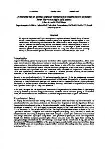
radial distributions. This gives rise to the interesting observation that, in general, the regions of maximum AM density, either of spin or orbital origin, are not the regions with maximum intensity (energy density). This is evident in Figs. 2e and 3a: The energy is concentrated in an inner dashed region and the orbital AM in an external one. Similarly, for the superposition of waves (19), the ring of maximum energy intensity in Fig. 2(f) as well as in Fig. 3(b) falls in a region of relatively small orbital AM. A comparison of the radial cross sections is given in Fig. 4(a). Following the analysis presented in Ref. [26] the angular velocity of an absorbing (or birefringent) object trapped by a beam carrying orbital (or spin) AM depends on the AM flux through the region occupied by the object itself. For paraxial beams this reduces to the average of the variation of the AM density introduced by the absorbing or birefringent object. The main point is that, if the trapping beam is a single LG mode, the angular velocity is proportional to the local absorbed energy, because this is equivalent to the AM density apart from a constant [26]. For more complex trapping beams, however, energy and AM can be tailored to be locally very different. Therefore the fastest rotation of an absorbing particle can appear even in regions of relative darkness of the beam. This separation between the regions where energy and AM are respectively concentrated offers the possibility to clearly distinguish the respective mechanical effects. In order to observe rotation of particles in dark regions of the transverse beam profile it is possible to use hollow spheres or any object with refractive index lower than the surrounding liquid medium [32]. In the following, we consider an alternative strategy, where for symmetry reasons a particle is trapped on the beam axis of a centrally symmetric beam. We propose an experiment to measure the angular velocity of a trapped object with circular or ring shape. The interference and superposition fields could be used to trap the object and a measurement made of the variation of the velocity by changing the relative radius of the beam and of the object, for instance by progressive focusing of the beam. The variation of the velocity will be proportional to the integral of the AM density over the object area and clearly distinguishable from the average energy. In Fig. 4(b) we illustrate the case of a circular purely absorbing object trapped by the field resulting from the superposition of two beams with same energies and different helicities. The average energy in a circular area always increases monotonically with the radius R. On the other hand, the orbital AM can show oscillations from negative to positive values if the composing beams have helicities with different signs. On focusing the beam, the angular velocity of the trapped object is predicted to change direction following the dashed line curve in Fig. 4(b). The asymptotic values for large R can be compared with Eqs. (20). We note that a na¨ıve picture of the angular velocity in terms of the transfer of some average number of units of orbital AM (J z ) per photon would translate in a wrong prediction of increasing angular velocity in a fixed direction. We consider now the spin AM when the orthogonal beams (19) are superposed. Even if the average spin AM is vanishing, we have seen that the local value of the Stokes parameter σ z (x) is dictated by the relative phases of the superimposed beams (E x and Ey ). The orthogonality of the spatial modes, does not prevent the possibility of finding a polarization pattern with large local spin AM. In particular, regions of left circular polarization are balanced by the ones with right circular polarization, as illustrated in Figs. 2c and g, and Fig. 3(c). The |! 1 − !2 | lobes [33] with left and right circular polarization are separated by regions of vanishing spin, or C-contours [34], while the energy is azimuthally symmetric. We conclude that the total AM density, and its spin and orbital components, can be concentrated near to regions of darkness in the beam.
#87436 - $15.00 USD
(C) 2007 OSA
Received 12 Sep 2007; revised 9 Oct 2007; accepted 9 Oct 2007; published 2 Nov 2007
12 November 2007 / Vol. 15, No. 23 / OPTICS EXPRESS 15223
Fig. 4. a) Radial energy density (continuous line) and orbital AM density (dashed line) obtained superposing two beams with !1 = 7, !2 = −1 (see Fig. 3(b)). b) Average energy (continuous line) and orbital AM (dashed line) obtained by integral on a circular area of radius R in units of ε0C2 and ε0C2 /ω , respectively.
3.1.2.
Modes with same helicities
In order to illustrate the specific effects encoded in the radial index, let us consider LG composing beams with the same helicity (!), but different radial indexes p 1 &= p2 : U(x) = Cu p1 ! (x),
V (x) = Cu p2 ! (x).
(23)
Due to the orthogonality of the modes we find again that the average AM as well as the energy are the same in interference and superposition, while the respective densities will in general be different. In particular, at the focal plane the orbital AM does not show any azimuthal modulation, even in the case of interference, and the spin density is uniform. However, the details of the pattern of both the superimposed and interfering beams depend on the propagation distance z, maintaining constant average values at different planes. Here we focus on the local spin generation induced by the respective Gouy phases exp[−i(2p j + |!| + 1) tan−1 (z/zR )] ( j = 1, 2) of superposed beams with different radial indexes. The relative Gouy phase introduces local polarization gradients, and hence non-vanishing spin AM density, in the form of opposite circular polarizations over different circles, as shown in Fig. 5. In the example, there is no spin at the focal plane, as the relative phase of the beams is vanishing everywhere, while for z &= 0 we see two circles of opposite spin (see the radial plot of the spin oscillating from positive to negative values in the left panel of Fig. 5). The Gouy phase is an odd function of z and so the spin density before and after the focal plane takes opposite values (compare panels for z = −0.5z R and +0.5zR in Fig. 5). Trapping bire f ringent particles near to a liquid surface and moving the focal plane away from the liquid surface should make it possible to show, experimentally, the effects of the Gouy phase and of the variation of the polarization pattern in different planes by observing the variation of the angular velocities of trapped objects. An interesting arrangement, fully exploiting the possibility to change rotation directions by moving the beam focal plane, would be a set-up with two concentric circular gears. Such an arrangement might be useful both for micromachining and microfluidic applications. Finally if U and V are in the same spatial mode (! 1 = !2 , p1 = p2 ) we have a single mode beam. Then, the orbital AMPE in superposition and interference is the same in spite of the fact that their energies and orbital AM are generally different. In other words, in this trivial case energy and AM interfere in the same way. No polarization patterns (local polarization gradients) appear in this case and the spin of the wave depends only on the relative (global) phases of the superimposed waves (the local and global properties of the spin are the same).
#87436 - $15.00 USD
(C) 2007 OSA
Received 12 Sep 2007; revised 9 Oct 2007; accepted 9 Oct 2007; published 2 Nov 2007
12 November 2007 / Vol. 15, No. 23 / OPTICS EXPRESS 15224
Fig. 5. Spin of the superposition of two orthogonal linearly polarized waves with same helicity ! = 2 and radial indexes p1 = 0, p2 = 1 at different planes along one Rayleigh range (zR ), for z = −0.5zR , 0, +0.5zR , +zR . In the first panel the radial profile is represented to show the local sign of the spin density. The Gouy phase introduces local polarization gradients out of the focal plane.
3.2. Interfering and superposing multimode beams LG modes are the ‘simplest’ beams carrying orbital AM. In the previous section we have studied the case of interference and superposition of two LG modes U and V . The minimum degree of complexity that can be added to this is by considering the patterns generated by superposing two beams not in single mode but still containing, over all, only two LG modes (same number of spectral components than in previous section): √ V (x) = C(u0!1 (x) + u0!2 (x))/ 2. (24) U(x) = Ceiθ u0!1 (x), Note that (i) U and V have the same average energy and (ii) they are clearly not orthogonal, as V results from the (constructive) interference of u 0!1 and another orthogonal mode (! 1 &= !2 ). This enables us to study the effects of both parallel and orthogonal mode components. The phase θ can be varied to have constructive or destructive interference between U and V . For in U$ and V is constructive leading −π /2 < θ < π /2 the interference of the parallel components # √ θ . The average orbital AM is to a larger energy than in the superposition: W zi = Wzs 1 + cos 2
Liz
=
Lsz
=
' ( 3 √ 1 + 2 cos θ !1 + !2 2 2 % ( 2 C ε0 3 1 !1 + !2 , 2ω 2 2 C2 ε0 2ω
%&
(25) (26)
and it is easily seen that if !1 is positive then Liz > Lsz , independently on the value of ! 2 . If !1 is negative, on the other hand and in spite of the constructive interference, the orbital AM is smaller in the interference pattern than in the superposition one. The same result is obtained for destructive interference (π /2 < θ < 3/2π ) and negative ! 1 . Assuming for simplicity that !1 , !2 > 0, we conclude that interfering constructively the beams (24) gives more average orbital angular momentum than superposing them. Surprisingly, even if there is more orbital AM in the interference case, this does not always mean that there is more orbital AMPE. In particular, it is possible to obtain more AMPE in the superposition than in the constructive interference case depending on the relative values of ! 1 and !2 . In general we find that (for constructive interference |θ | < π /2) Liz Lsz < Wi Ws
for !1 < !2 .
(27)
For destructive interference the same result holds but for ! 1 > !2 . Remember that in the case of #87436 - $15.00 USD
(C) 2007 OSA
Received 12 Sep 2007; revised 9 Oct 2007; accepted 9 Oct 2007; published 2 Nov 2007
12 November 2007 / Vol. 15, No. 23 / OPTICS EXPRESS 15225
Fig. 6. Regions (shaded) in which there is more total AM (left) and more total AMPE (right) in superposition than in interference, as function of the angle θ and !1 , for a fixed !2 = 2.
orthogonal beams (previous section) the orbital AM as well as the orbital AM per photon were the same in either interference or superposition. The study of the interference and superposition of the beams (24), with a low degree of spectral complexity (only two modes), shows that even if the average orbital AM is larger for constructively interfering the beams than for superposing them (cos θ > 0, !1 > 0), the superposition can still be more efficient in providing the largest orbital AMPE (if !1 < !2 ). The beam obtained by superposing the two orthogonally polarized waves (24) also carries an average spin angular momentum. The main point is that only the parallel components (in the orbital AM states) of U and V can contribute to the spin, as discussed above (Eq. 18). From Eqs. (24) it follows that the average spin AM is
ε0C2 Szs = − √ sin θ . 2ω
(28)
√ s Note that Szs /W √ = − sin θ / 2ω and for a relative phase of θ = −π /2, the spin per photon would be h¯ / 2. This value is less than expected ( h¯ per photon for circularly polarized light) because the same LG modes for E x and Ey have different amplitudes. The comparison between the interference and superposition beams, including also the spin, is obtained by comparison of the total AM % ( √ C2 ε0 3 1 s !1 + !2 − 2 sin θ Jz = (29) 2ω 2 2 with Eq. 25 (Jzi = Liz ). It follows that Jzs > Jzi if − sin θ > !1 cos θ
(30)
These simple relations provide the conditions to maximize the resulting AM (and AMPE) chosing between superposition and interference, as shown in Fig. 6. 4. Conclusion The properties of angular momenta and energy of multimode light beams have been discussed, illustrating their main differences with the case of single LG modes. The latter are known to have energy and AM related by constant proportionality factors, both locally and globally. On the other hand, the interference of LG modes allows us to tailor the mechanical properties #87436 - $15.00 USD
(C) 2007 OSA
Received 12 Sep 2007; revised 9 Oct 2007; accepted 9 Oct 2007; published 2 Nov 2007
12 November 2007 / Vol. 15, No. 23 / OPTICS EXPRESS 15226
of these beams into different density profiles. Superposition of orthogonal linearly polarized beams was also discussed and we showed how the vectorial character of the electromagnetic field makes it possible to tune independently the x and y components of the linear momentum introducing also locally varying spin (polarization patterns). Unlike interference, superposition allows us to add both the energy and orbital AM of orthogonally polarized field components, without introducing any azimuthal modulation. The ability to engineer independently the local density of orbital AM and energy opens up the possibility to distinguish the respective effects of light intensity and optical AM in lightmatter interactions. In particular, the AM density can be maximum in regions of relatively low intensity, where hollow particles would be naturally trapped. This may have important implications in the context of optical trapping including, for example, the possibility of rotating without burning. Similarly, if small absorbers are used to map the transverse profile of a generic beam then the faster rotations will not necessarily be observed in the regions of maximum intensity. We proposed an experiment to clarify the distinctive role of energy and AM by measuring the angular velocity of an absorbing object, trapped by a multimode beam as it is focused. The generic picture of mechanical effects in terms of the absorption of photons carrying an average orbital AM is not appropriate for mutlimode beams and the local AM distribution needs to be evaluated. We also described a simple way to create polarization patterns, with azimuthal symmetry, provided by the Gouy phase. Superposing LG modes with different radial indexes but the same helicity, it is possible to create patterns with rings of opposite spin out of the focal plane, even if the average spin AM is zero. The global AM and AMPE of multimode beams were also discussed. If the component beams are orthogonal then the same average orbital AM and energies are found in interference and superposition, while the average spin is always zero, independently of the relative phase. On the other hand, the global properties can be changed even maintaining the same two composing LG modes when increasing the beam complexity: given the fields (24) we found (i) different average AM and energies for interference and superposition, (ii) with non-vanishing spin, and (iii) we identified the conditions to have larger resulting AM and AMPE in superposition than in interference depending on the phases and helicities of the component beams. Acknowledgments This work was funded by the ”Ministerio de Educacion y Ciencia” (Ramon y Cajal contract and CONOCE2 grant FIS2004-00953), the ”Govern Balear” (PROGECIB-5A project) and in part by the UK Engineering and Physical Sciences Research Council. SMB thanks the Royal Society and the Wolfson Foundation for financial support.
#87436 - $15.00 USD
(C) 2007 OSA
Received 12 Sep 2007; revised 9 Oct 2007; accepted 9 Oct 2007; published 2 Nov 2007
12 November 2007 / Vol. 15, No. 23 / OPTICS EXPRESS 15227