IEEE/ASME TRANSACTIONS ON MECHATRONICS, VOL. 7, NO. 1, MARCH 2002
87
Optimization and Implementation of Multimode Piezoelectric Shunt Damping Systems Andrew J. Fleming, Member, IEEE, Sam Behrens, and S. O. Reza Moheimani, Senior Member, IEEE
Abstract—Piezoelectric transducer (PZT) patches can be attached to a structure in order to reduce vibration. The PZT patches essentially convert vibrational mechanical energy into electrical energy. The electrical energy can be dissipated via an electrical impedance. Currently, impedance designs require experimental tuning of resistive circuit elements to provide optimal performance. A systematic method is presented for determining the resistance values by minimizing the 2 norm of the damped system. After the design process, shunt circuits are normally implemented using discrete resistors, virtual inductors and Riordian gyrators. The difficulty in constructing the shunt circuits and achieving reasonable performance has been an ongoing and unaddressed problem in shunt damping. A new approach to implementing piezoelectric shunt circuits is presented. A synthetic impedance, consisting of a voltage controlled current source and a digital signal processor system, is used to synthesize the terminal impedance of a shunt network. A two-mode shunt circuit is designed and implemented for an experimental simply supported beam. The second and third structural modes of the beam are reduced in magnitude by 22 and 18 dB. Index Terms—Damping, piezoelectric, resistor, shunt, synthesis.
I. INTRODUCTION
T
ODAY’S increasingly highspeed and lightweight structures are subject to extensive vibrations that can reduce structural life and contribute to mechanical failure. Piezoelectric transducers (PZTs) in conjunction with appropriate circuitry, can be used as a mechanical energy dissipation device. By placing an electrical impedance across the terminals of the PZT, the passive network is capable of damping structural vibrations. If a simple resistor is placed across the terminals of the PZT, the PZT will act as a viscoelastic damper [1]. If the network consists of a series inductor–resistor – circuit, the passive network combined with the inherent capacitance of the PZT creates a damped electrical resonance. The resonance can be tuned so that the PZT element acts as a tuned vibrational energy absorber [1]. This damping methodology is commonly referred to as passive shunt damping. Passive shunt damping is regarded as a simple, low cost, lightweight and easy to implement method of controlling structural vibrations. A desirable property of passive shunt damping is that the controlled system is guaranteed to be stable in the presence of structural uncertainties. Flexible mechanical structures have an infinite number of resonant frequencies (or structural modes). If the tuned energy absorber [1] is used to minimize the vibration of a number of Manuscript received March 10, 2000; revised March 9, 2001. Recommended by Technical Editor C. H. Menq. This work was supported by the Australian Research Council. The authors are with the Department of Electrical Engineering and Computer Science, University of Newcastle, Callagahan 2308, Australia (e-mail:
[email protected]). Publisher Item Identifier S 1083-4435(02)02100-2.
modes, one would need an equal number of PZT patches and shunting circuits. This is clearly impractical. Wu [2] reports a method of damping multiple vibration modes using a single PZT. The proposed circuit includes a “current blocker” consisting of a parallel capacitor–inductor network placed in series with each – shunt circuit designed for one structural mode. Depending on the number of structural modes to be shunt damped simultaneously, a different number of – networks are placed in series with each parallel – shunt branch. Although shunt damping circuits have a fixed structure, the designer is still faced with the problem of choosing component values. The blocking circuit and branch inductance values are easily found using classical circuit theory and the resonant frequencies of the structure. Damping resistors are currently determined experimentally by observing the frequency response of the damped system and varying the resistances to achieve a desirable tradeoff between peak reduction and side-lobe amplitude [2]–[8]. An optimization technique is proposed that minimizes norm of the damped system. This provides a systematic the and reliable method for designing the resistance values of shunt damping circuits. There are also a number of implementation problems associated with single and multimode shunt damping techniques. PZT shunt circuits typically require large inductance values. Therefore, virtual inductors are required to implement the inductor elements. Virtual inductors are large in size and sensitive to component variations and nonideal characteristics. PZT shunt circuits are capable of generating large voltages for moderate structural excitations. This requires that the virtual inductor circuits be constructed from high voltage operational amplifiers. At least 30 high voltage opamps are required to damp three structural modes.1 This paper introduces a method of implementing a specified shunt circuit with arbitrary order and complexity. The “synthetic impedance” uses a voltage dependant current source and digital signal processor (DSP) system to implement the terminal impedance of an arbitrary shunt network. It replaces physical circuits to provide effective structural damping without the problems encountered with direct circuit implementations. II. PIEZOELECTRIC SHUNT DAMPING Shunt damping methodologies are often grouped into two broad categories: single mode and multimode. Single mode shunt damping techniques are simple but damp only one structural mode for every PZT. Multiple mode shunt damping techniques require more complicated shunt circuits but are capable of damping many modes. 1Based on a series circuit configuration with current blocker’s in every branch, as shown in [2].
1083–4435/02$17.00 © 2002 IEEE
88
IEEE/ASME TRANSACTIONS ON MECHATRONICS, VOL. 7, NO. 1, MARCH 2002
Fig. 1. Examples of shunt circuits. Single mode: (a) parallel case and (b) series case. Multimode: (c) parallel case [2] and (d) series case.
A. Single Mode Shunt Damping Single mode damping was introduced to decrease the magnitude of one structural mode [4]. Two examples of single mode damping are shown in Fig. 1, parallel and series shunt damping. An – shunt circuit introduces an electrical resonance. This can be tuned to one structural mode in a manner analogous to a mechanical vibration absorber. Single mode damping can be applied to reduce several structural modes with the use of as many piezoelectric patches and damping circuits. Problems may result if these piezoelectric patches are bonded to, or imbedded in the structure. First, the structure may not have sufficient room to accommodate all of the patches. Second, the structure may be altered or weakened when the piezoelectric patches are applied. In addition, a large number of patches can increase the structural weight, making it unsuitable for applications such as aerospace. B. Multiple Mode Shunt Damping Toalleviatetheproblemsassociatedwithsinglemodedamping, multimode shunt damping has been introduced; i.e., the use of one piezoelectric patch to damp several structural modes. There are two common circuit configurations for multimode shunt damping, parallel and series. Examples of these two configurations are shown in Fig. 1. There are other examples of multimode shunt damping but these will not be discussed in this paper. Theprincipleofmultimodeshuntdampingistoinserta“current blocking” circuit [2], [6]–[8] in series with each shunt branch. In Fig. 1(d), the blocking circuit consists of a capacitor and inductor – The number of antiresonant circuits in each in parallel, – shunt branch depends on the number of structural modes to be damped simultaneously. Each – shunt branch is designed – in Fig. 1(c) is to damp one structural mode. For example, tunedtoresonateat ,theresonantfrequencyofthefirststructural – is tuned to , the second structural mode to be damped. mode to be damped and so on. According to Wu [2], the inductance values for the shunt circuits shown in Fig. 1(c) and (d) can be calculated from the following expressions. It is assumed that
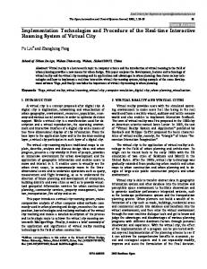
Fig. 2. Piezoelectric laminated simply supported beam.
where is the capacitance of the PZT and is an arbitrary capacitor used in the current blocking network. In the following will be taken as 100 . Sections C. Implementation Difficulties Currently, shunt damping circuits are implemented using a network of physical components. There are a number of problems associated with this direct circuit implementation, the foremost of which are listed below. • Typically the shunt circuits require large inductor values (up to thousands of henries). Virtual grounded and floating inductors (Riordan gyrators [9]) are required to implement the inductor elements. Such virtual implementations are typically poor representations of ideal inductors. They are large in size, difficult to tune, and are sensitive to component age, temperature, and nonideal characteristics. • Piezoelectric patches are capable of generating hundreds of volts for moderate structural excitations. This requires the entire circuit to be constructed from high voltage components. Further voltage limitations arise due to the internal gains of the virtual inductors. • The minimum number of opamps required to implement the shunt damping circuit increases rapidly with the number of modes to be damped. At least 30 opamps are required to implement a series configuration multimode shunt damping circuit with current blocker’s in every branch. The relationship between the number of opamps and the number of modes to be damped for this circuit , configuration is given by where is the number of modes to be damped. III. MODELLING THE COMPOUND SYSTEM In this Section we sketch how the dynamics of a simply supported piezoelectric laminate beam as illustrated in Fig. 2 can be derived. Two piezoelectric patches are bonded to the structure using a strong adhesive material. One PZT will be used as an actuator to generate a disturbance and the other as a passive
FLEMING et al.: MULTIMODE PIEZOELECTRIC SHUNT DAMPING SYSTEMS
89
shunting layer. The subscripts “ ” “ ” and “ ” correspond, respectively, to the actuating piezoelectric layer, the beam and the shunting piezoelectric layer. A. Structural Dynamics of a Simply Supported Beam When modeling the dynamics of a structure, it is common practice to derive the transfer function between the displacement at any point along the beam and the actuator voltage, and also the transfer function between i.e., the shunting piezoelectric voltage and the actuator voltage . The elastic deflection of a simply supported beam is described by the one dimensional Bernoulli–Euler beam equation which has been modified [10] as shown below: (1) where , , , and represent the Young’s modulus, moment of inertia, cross-sectional area, and linear mass density of the beam, respectively. The additional term is due to the moment applied to the neutral axis of the beam by the actuator piezowhere is a constant electric layer, i.e., dependent on the actuator properties [11]–[13]. It is assumed that each piezoelectric patch is very thin and that the beam deflects only in the axis. Simply supported boundary condiand tions imply . By using the modal analysis technique [14] the position func, can be expanded as an infinite series of the form tion , where are the normalized [14] mode shapes given by are the modal displacements [10]. and To formulate the dynamical response of the system, the Lagrange equations [14] are used to find the differential equation corresponding to each mode (2)
Fig. 3.
Shunted PZT schematic.
Laplace transform, the transfer function from the actuator to shunt voltage is found to be [15]
The transfer functions represented in state-space form as
(4) can be
and
(5) where
is the beam state vector, and and .
and
depend on
B. Compound Dynamics As discussed in Section II-B, there are two common circuit configurations used for multimode shunt damping, series and parallel as shown in Fig. 1. In order to model the presence of the shunt network, the coupled terminal dynamics of the circuit and laminated beam are considered. Piezoelectric transducers behave electrically like a capacitor and mechanically like a stiff spring. It is common to model in series with a the piezoelectric element as a capacitor strain dependent voltage source [1], [16]. Consider Figs. 2 and 3, where a piezoelectric patch is shunted with an impedance . The current-voltage relation of the impedance can be represented in state-space form as
The PZT sensor voltage can be described by where is the piezoelectric constant of to the PZT [10]. In the sequel we will use the notation represent the derivatives with respect to the spatial variable and time , respectively. The resonant frequencies are given . by The dynamic response is found by taking the Laplace transform of the above equation and substituting
is the voltage across the impedance and is the curwhere rent flowing through the circuit. The relationship between and , shown in Figs. 2 and 3, is
(3)
(8) (9)
The above equation describes the elastic deflection of the entire flexible beam due to a voltage applied to the piezoelec, are added tric actuator. Note that the additional terms to compensate for structural damping and are usually found experimentally. The shunting layer voltage can be expressed . By taking the as
(6) (7)
where is the voltage induced from the electromechanical coupling effect. By shunting the piezoelectric patch, the voltage across the shunting layer or impedance, is related to the terminal voltage and current by (10)
90
IEEE/ASME TRANSACTIONS ON MECHATRONICS, VOL. 7, NO. 1, MARCH 2002
The variable , can be replaced with , the charge on the PZT. and substituting Consequently, by replacing (6)–(8) become
the gradient search algorithm. By introducing the matrix of Lagrange multipliers the Lagrangian is formed as follows: (15)
(11)
If a voltage
The first-order necessary conditions for optimality are found by equating the derivatives of with respect to the parameters , , and to zero
is applied to the actuator PZT, then (11) becomes
(16) (17)
(12) ,
where , and
.. .
, .
IV. DETERMINING VIA
THE SHUNTING OPTIMIZATION
(18)
RESISTANCES
In order to find appropriate values for the shunt resistors an optimization approach is proposed; a set norm of the damped of resistors can be found so that the norm of the system system is minimized. Minimizing the minimizes the RMS displacement at a single, or series of points due to a spectrally white disturbance signal applied to the actuator(s). A. Optimization Technique Consider a transfer function matrix norm of senting the damped system (12). The , is defined as
resistors, can be represented as , where is independent of . norm of the system can now be minimized by solving The the above equations simultaneously. It is not possible to obtain a closed form solution, so a numerical approach is required. As preliminaries for the optimization, the static matrices ( and ) are computed and an initial estimate is made for . and is updated at each iteration. Matrix is a function of Matrices and , are calculated by solving the Lyapunov equations (16) and (17). The direction of steepest descent is found by evaluating the gradient vector, whose entries are the par(18). The tial derivatives of with respect to until a minima is obtained process is iterated by updating and (i.e., until the exiting conditions are satisfied). With
repre, denoted
V. IMPLEMENTATION OF SHUNT DAMPING CIRCUITS
Let matrix
have the realization is stable the following equality holds:
. If the
(13) where
satisfies the Lyapunov equation . This leads to the following constrained optimization
problem: (14) and , . Having set up the optimization problem (14), a number of methods can be employed to find an optimal set of re. One such method is the sistors Nelder-Mead simplex search algorithm. A more elegant and computationally efficient method of solving (14) is to use
It should be clear from previous sections that although the concept of multimode shunt damping is useful, implementation difficulties make its application somewhat limited. This section introduces a new method of implementing complicated shunt damping circuits using only a few opamps, one resistor, and a DSP. A. Synthetic Impedance We define a “synthetic impedance” as a two terminal device that establishes an arbitrary relationship between voltage and current at its terminals. The functionality is shown in Fig. 4, . This can be made to synthesize any where network of physical components by fixing to be the output of a linear transfer function of . i.e.
where
(19) and is the impedance to be seen where can be implefrom the terminals. The transfer function mented with an analog filter or DSP system. A DSP system is used here for flexibility and ease of implementation.
FLEMING et al.: MULTIMODE PIEZOELECTRIC SHUNT DAMPING SYSTEMS
91
TABLE I BEAM PARAMETERS
Fig. 4. Current source implementation. TABLE II PEIZOELECTRIC PARAMETERS
B. Synthesis of Piezoelectric Shunt Damping Circuits A synthetic impedance that implements the multimode shunt damping circuit shown in Fig. 1(d) will now be designed. The implementing circuit is similar to the example implementation shown in Fig. 4. A voltage controlled current source constructed from a single opamp is used together with buffer/amplifiers and a DSP system to simulate an impedance. The two unity gain buffers are replaced with noninverting amplifiers of gain 1/10 and 10. This retains the functionality while allowing the DSP system to operate at a voltage ten times lower than that dealt with by the current source and buffer/amplifiers. A voltage protection device is placed at the input to the DSP analog to digital converter. The only required high voltage components are now the buffer/amplifier and current source opamp. The resets the transconductance gain of the system. In order sistor to minimize quantization error, a reasonable portion of the digital to analog converters range should be utilized. A larger resistor requires a larger voltage to provide a specified current. To maintain a unity transconductance, a gain equal to the value of should be placed internally in the DSP algothe resistance rithm. The DSP system should be programmed to implement the admittance transfer function of the damping network. In this paper, Simulink2 and the Real Time Workshop for Matlab are used to generate the DSP application.3 VI. EXPERIMENTAL RESULTS To assess the merit of the concepts presented, a number of experiments were carried out on a simply supported piezoelectic laminate beam. By identifying the resonant frequencies and damping ratios of the beam, a 5-mode (tenth order) truncated model is constructed. The optimization technique described in Section IV-A is then employed to determine the optimal shunt resistances. Finally, the optimal parallel and series shunt circuits are synthesized and applied to the structure. Damping performance is evaluated by measuring the free and damped frequency responses of the beam.
ditions at both ends. A pair of piezoelectric ceramic patches (PIC151) are attached symmetrically to either side of the beam surface. One patch is used as an actuator and the other as a shunting layer. Experimental beam and piezoelectric parameters are summarized in Tables I and II. The displacement and voltage frequency responses are measured using a Polytec laser vibrometer (PSV-300) and a HP spectrum analyzer (35670A). In both cases a swept sine excitation is applied to the actuator PZT. The current source and buffer/amplifiers required for the synthetic impedance are constructed from Burr Brown OPA445 opamps. These opamps have a supply voltage limit of 45 v. For applications requiring higher terminal voltages, high voltage opamps are required. Such devices, specifically designed for driving piezoelectric transducers, are readily available. B. Optimization Results In order to perform the optimization, an accurate model of the system is required. For obvious reasons the infinite-order model produced by the modal analysis technique is not suitable for use in the optimization. As an alternative, the displacement and voltage frequency responses are measured and used to tune a finite-order model with the following structure:
A. Experimental Setup The experimental beam is a uniform aluminum bar with rectangular cross section and experimentally pinned boundary con2A
graphical simulation environment for Matlab. target processing hardware is the dSPACE ds1103 processing and I/O board. 3The
where and are the zero frequency correction terms introduced in [15]. The frequency response of the experimental
92
IEEE/ASME TRANSACTIONS ON MECHATRONICS, VOL. 7, NO. 1, MARCH 2002
Fig. 5. Frequency response of (a) Experimental (1 1 1) modeled (—).
V
(s))=(V (s), (b)
d(0:170; s)=V
(s).
Fig. 6. Cost surface—parallel case.
system and identified model is shown in Fig. 5. It is observed that the identified model is a good representation of the true system over the bandwidth of interest. Although the truncated model can be found to minimize the norm of the additive error system [15], the inherent feed causes the norm of the corrected system to apthrough proach infinity. To overcome this adverse effect, the corrected system
is remodeled with an additional parallel
. If low-pass filter and , the dynamics of the system over the bandwidth of interest are retained. The state-space realization becomes Fig. 7. Cost surface—series case.
(20)
TABLE III OPTIMIZATION CIRCUIT PARAMETERS
where
is the state-space realization of the filter . Note that the has been eliminated. Because the confeed through term troller is of fixed structure, the dynamics of the introduced filter will not effect the optimization. The technique presented in Section IV-A can now be applied. With the aim of damping the second and third structural modes, the optimization is performed for both the series and parallel circuit configurations. The second and third modes are chosen for their high resonant peaks and because the location of the PZT provides the greatest authority over these two modes. (See [17] for a discussion of PZT placement issues.) The cost surfaces and a summary of the optimization results are shown in Figs. 6 and 7 and Table III.
In an earlier report where experimental tuning is performed [6], Wu makes the observation that the parallel circuit is easier to tune. This claim is justified by Figs. 6 and 7 that clearly show a greater sensitivity to resistance variations in the series cost surface. C. Damping Performance The optimized series and parallel shunt circuits are now applied to the beam. As shown in Section V-B, the admittance of the damping network is formed, compiled, then downloaded onto the DSP hardware. The dSPACE DS1103 processing and I/O board was chosen as the target DSP hardware.
FLEMING et al.: MULTIMODE PIEZOELECTRIC SHUNT DAMPING SYSTEMS
93
TABLE IV DAMPING PERFORMANCE
Fig. 8.
jd(0:170; s)=V
(s)j Experimental (1 1 1) and theoretical (—).
are prone to undesirable resonant vibrations that can reduce structural life and contribute to mechanical failure. Considerable research has been undertaken with the aim of damping these vibrations using a piezoelectric transducer and shunt damping circuit. Results to date have been encouraging but have lacked a systematic solution and practical implementation. Previous design techniques have relied on the experimental tuning of circuit parameters to provide adequate performance. By modeling the compound system, an optimization problem norm of the rehas been formulated that minimizes the sulting system. This provides a systematic procedure for designing fixed structure shunt damping circuits. Previous shunt damping methodologies have also suffered from issues relating to the difficulty in implementing the shunt network. A synthetic impedance has been presented that implements the terminal impedance of a specified shunt network. The concepts presented have been experimentally verified with good results. The modal resonant magnitudes have been reduced by up to 22 dB, this corresponds to a damped settling time 1/10th that of the free response.4 In general, theoretical predictions have been coherent with experimental results. Future work will involve remodeling the shunt damping problem in a feedback control systems perspective. This is now possible as an impedance of arbitrary structure can be implemented. REFERENCES
Fig. 9. Experimental time domain results.
Fig. 8 shows the theoretical and experimental damped frequency response. Fig. 9 shows the experimental time domain response to a filtered step disturbance (bandpass filtered between 40 and 200 Hz). A summary of the performance is provided in Table IV Itisnotedthatthesameexperimentshavebeenperformedusing discrete resistors, virtual inductors, and Riordan gyrators [18]. Nonidealities in the virtual inductors result in a poor correlation between experimental and predicted frequency responses. Peak damping performance is 3–5 dB lower than that achieved here. The synthetic impedance has proven to be a high performance method of implementing shunt damping circuits. It has a low number of high voltage components, is immune to component nonideality and requires no tuning of sensitive virtual circuits. VII. CONCLUSIONS Modernhighperformancedesignspecificationshavegivenrise to the widespread use of lightweight structures. These structures
[1] N. W. Hagood and A. von Flotow, “Damping of structural vibrations with piezoelectric materials and passive electrical networks,” J. Sound Vib., vol. 146, no. 2, pp. 243–268, 1991. [2] S. Y. Wu, “Method for multiple mode shunt damping of structural vibration using a single PZT transducer,” in Proc. SPIE Smart Structures and Materials, Smart Structures and Intelligent Systems, vol. 3327, Mar. 1998, pp. 159–168. [3] D. L. Edberg, A. S. Bicos, C. M. Fuller, J. J. Tracy, and J. S. Fechter, “Theoretical and experimental studies of a truss incorporating active members,” J. Intell. Materials Syst. Structures, vol. 3, pp. 333–347, 1992. [4] N. W. Hagood and E. F. Crawley, “Experimental investigation of passive enhancement of damping for space structures,” J. Guid., Control Dyn., vol. 14, no. 6, pp. 1100–1109, 1991. [5] J. J. Hollkamp, “Multimodal passive vibration suppression with piezoelectric materials and resonant shunts,” J. Intell. Materials Syst. Structures, vol. 5, pp. 49–56, 1994. [6] S. Y. Wu, “Piezoelectric shunts with parallel R-L circuit for structural damping and vibration control,” in Proc. SPIE Smart Structures and Materials, Passive Damping and Isolation, vol. 2720, SPIE, Mar. 1996, pp. 259–269. [7] , “Multiple PZT transducers implemented with multiple-mode piezoelectric shunting for passive vibration damping,” in Proc. SPIE Smart Structures and Materials, Passive Damping and Isolation, vol. 3672, Mar. 1999, pp. 112–122. 4For
the excitation described in Section VI-C.
94
IEEE/ASME TRANSACTIONS ON MECHATRONICS, VOL. 7, NO. 1, MARCH 2002
[8] S. Y. Wu and A. S. Bicos, “Structural vibration damping experiments using improved piezoelectric shunts,” in Proc. SPIE Smart Structures and Materials, Passive Damping and Isolation, vol. 3045, Mar. 1997, pp. 40–50. [9] R. H. S. Riordan, “Simulated inductors using differential amplifiers,” Electron. Lett., vol. 3, no. 2, pp. 50–51, 1967. [10] C. R. Fuller, S. J. Elliott, and P. A. Nelson, Active Control of Vibration. New York: Academic, 1996. [11] H. R. Pota and T. E. Alberts, “Multivariable transferunctions for a slewing piezoelectric laminate beam,” ASME J. Dynamics Syst., vol. 117, pp. 353–359, 1995. [12] T. E. Alberts, T. V. DuBois, and H. R. Pota, “Experimental verification of transfer functions for a slewing piezoelectric laminate beam,” Contr. Eng. Practice, vol. 3, no. 2, pp. 163–170, 1995. [13] T. E. Alberts and J. A. Colvin, “Observations on the nature of transfer functions for control of piezoelectric laminates,” J. Intell. Materials Syst. Structures, vol. 8, no. 5, pp. 605–611, 1991. [14] L. Meirovitch, Elements of Vibration Analysis, 2nd ed. New York: McGraw-Hill, 1996. [15] S. O. R. Moheimani, “Experimental verification of the corrected transfer function of a piezoelectric laminate beam,” IEEE Trans. Contr. Syst. Technol., vol. 8, pp. 660–666, July 2000. [16] J. J. Dosch, D. J. Inman, and E. Garcia, “A self-sensing piezoelectric actuator for collocated control,” J. Intell. Materials Syst. Structures, vol. 3, pp. 166–185, Jan. 1992. [17] S. O. R. Moheimani and T. Ryall, “Considerations in placement of piezoceramic actuators that are used in structural vibration control,” in Proc. IEEE Conf. Decision and Control, Pheonix, AZ, Dec. 1999, pp. 1118–1123. [18] S. Behrens and S. O. R. Moheimani, “Optimal resistive elements for multiple mode shunt-damping of a piezoelectric laminate beam,” in Proc. IEEE Conf. Decision and Control, Sydney, Australia, Dec. 2000, pp. 4018–4023.
Andrew J. Fleming was born in Dingwall, U.K., in 1977. He received the B.E. degree (Elec.) with honors from the University of Newcastle, Callagahan, Australia, in 2000, and where he is currently pursuing the Ph.D. degree. He is a member of the Center for Integrated Dynamics and Control and the Laboratory of Dynamics and Control of Smart Structures. His current research interests include the passive and shunt impedance control of piezoelectric laminated structures and system identification of distributed parameter systems.
Sam Behrens (M’01) was born in Sydney, Australia, in 1975. He received the B.Eng. degree (mech.) and the M.E. degree from the Department of Electrical and Computer Engineering, University of Newcastle, Callagahan, Australia, in 1999 and 2001, respectively. He is a member of the Center for Integrated Dynamics and Control and the Laboratory of Dynamics and Control of Smart Structures. His research interests include passive, semi-active and self-sensing vibration control of piezoelectric laminated smart structures.
S. O. Reza Moheimani (S’93–M’97–SM’00) was born in Shiraz, Iran, in 1967. He received the B.Sc. degree from Shiraz University, Shiraz, Iran, in 1990, and the M.Eng.Sc. and Ph.D. degrees from the University of New South Wales, Sydney, Australia, in 1993 and 1996, all in electrical and electronic engineering. In 1996, he was a Postdoctoral Research Fellow at the School of Electrical and Electronic Engineering, Australian Defense Force Academy, Canberra, Australia. In 1997, he joined the Department of Electrical and Computer Engineering, University of Newcastle, Callagahan, Australia, where he is currently a Senior Lecturer. He current research interests include smart structures, mechatronic systems, control theory and signal processing. He is an Associate Editor for Control Engineering Practice and a member of the International Federation of Automatic Control (IFAC) Technical Committee on Mechatronic Systems. He is currently serving on the editorial boards of several international conferences, including the 2nd IFAC Conference on Mechatronic Systems, to be held in Berkeley, CA, in December 2002. Dr. Moheimani is a member of the Center for Integrated Dynamics and Control, an Australian government special research center.