ANTENNA DESIGN AND CHARACTERIZATION BASED ON THE ELEMENTARY ANTENNA CONCEPT
ANTENNA DESIGN AND CHARACTERIZATION BASED ON THE ELEMENTARY ANTENNA CONCEPT
PROEFSCHRIFT ter verkrijging van de graad van doctor in de technische wetenschappen aan de Technische Hogeschool Delft, op gezag van de Rector Magnificus, prof. dr. J.M. Dirken, in het openbaar te verdedigen ten overstaan van het College van Dekanen op 10 december 1985 te 16.00 uur
door
Leonardus Petrus Ligthart
n
1985 DUTCH EFFICIENCY BUREAU - PIJNACKER
TR diss 1466
ANTENNA NIGHTMARE
Dit proefschrift is goedgekeurd door de promotor Prof. ir. L. Krul
Antennas Are
and
cause
A novel Brings Until
propagation
for
bliss
and
design joy near
you
check
divine cross
polarization.
Leopold
C1P-6E6EVENS KONINKLIJKE BIBLIOTHEEK, Liqthart.
L e o n a r d us
DEN HAAG
Petrus
A n t e n n a d e s i g n and c h a r a c t e r i z a t i o n based on t h e elementary antenna concent / Leonardus Petrus L i g t h a r t . - Piipacker : Dutch E f f i c i e n c y B u r e a u . - 1 1 1 . P r o e f s c h r i f t D e l f t . - Met l i t . o p g . ~ Met s a m e n v a t t i n g i n het Nederlands. ISBN 9 0 - 6 2 3 1 - 1 4 5 - 8 SISO 6 6 9 . 2 UDC 6 2 1 - 3 9 6 . 6 7 Trefw.: antennes.
I
frustration
B.
Felsen
CONTENTS
ACKNOWLEDGEMENTS
SUMMARY
.
.
.
.
.
.
GENERAL INTRODUCTION
.
.
.
.
.
.
.
CHAPTER 1 THE ELEMENTARY ANTENNA .
.
.
.
.
.
.
.
11
.
.
.
.
.
.
.
13
.
.
.
15
.
.
.
21
.
.
21
.
. .
.
.
Properties of the elementary antenna
1.3
The role of the currents through the contour
1.4
Computational techniques
.
OPEN-ENDED WAVEGUIDES .
.
. .
.
. .
.
2.2
Parallel-plate TEM waveguide
2.3
Rectangular waveguides with TE or TM mode excitation
.
.
.
.
.
.
Introduction
.
.
22
.
31
.
37
.
.
41
.
.
41
.
. .
. .
.
52
Circular waveguide with TE or TM mode excitation
Higher-order mode excitation for the parallel-plate TEM waveguide
2.6
Higher-order mode excitation at the T E
2.7
Experimental results
.
3.1 3.2
.
45
2.5
.
.
42 .
2.4
.
.
.
.
.
2.1
.
. .
.
. .
. .
.
. .
.
.
.
. .
.
. .
.
waveguide aperture . .
.
.
.
.
Introduction
.
61 65
.
.
.
.
. .
. .
. .
.
.
.
.
.
.
.
69
.
69
Electromagnetic phenomena at the aperture of the TEM waveguide radiator
.
.
.
.
.
.
.
.
.
.
3.4
Results of a C band dielectric filled TEM waveguide radiator
SMALL TE
Introduction
.
.
Aperture matching of the TEM waveguide radiator
CHAPTER 4
.
.
3.3
4.1
57 .
SMALL SINGLE POLARIZATION TEM WAVEGUIDE RADIATOR WITH A RECTANGULAR CROSS SECTION
Part of this thesis was performed in a joint project with the Dr. Neher
.
.
Introduction
.
.
.
1.2
CHAPTER 3
Laboratory (PTT), Leidschendam, the Netherlands.
.
1.1
CHAPTER 2
.
.
.
.
.
.
.
.
.
.
.
.
78 .
RADIATORS WITH A RECTANGULAR CROSS SECTION .
71 .
. .
33
91 91
4.2
Aperture reflections of the TE
radiator with a square cross
section
.
.
.
.
.
.
.
.
.
.
VII.3 VIII
.
IX X
cross section
.
.
.
.
.
. .
. .
. .
Aperture matching
.
4.4.2
Coax waveguide adapters for the dual polarized TE .
.
.
.
.
.
.
.
section
.
.
.
.
.
.
.
.
System performance of the five-element array
5.4
Hybrid reflector array measurements
.
.
.
.
113
SAMENVATTING
.
BIOGRAPHY
.
.
.
.
.
. .
.
.
. .
.
.
120 .
124
.
130
.
.
.
.
.
.
.
.
.
135
REFERENCES
.
.
.
.
.
.
.
.
.
.
.
.
137
APPENDICES Radiation pattern of the elementary antenna derived from the vector potential method
.
.
.
.
.
.
.
.
.
.
140
Electromagnetic Field Integral Equations starting from Green's and Lorentz' Reciprocity Theorem
.
.
.
Boundary values of the circular TEM antenna
. .
. .
.
.
Reflection coefficient of the circular TEM aperture
.
. .
143
. .
147 .
143
Transmission coefficient of the TEM waveguide without mode excitation 149 Reflection and transmission coefficient of TE without mode excitation
VII
162
Matching conditions based on the S matrix coefficients of a matching network placed at the reflection reference plane
.
V
160
XIII
.
VI
.157
.
105
.
IV
.
.
XII
CONCLUSIONS
III
.
the transition of two media with different dielectric constants
101
Introduction
5.3
II
.
Matching to be used for the dielectric filled TEM waveguide ,
XI
Optimization
I
.
155
Reflection and transmission coefficients of uniform plane waves at
101
waveguide
.
Measurement technique of radiation patterns
154 .
.
.
Scattering matrix of a matching network with airgap
.
.
163
.
.
.
165
.
.
.167
.
169
Experimental results of the prototype of the dual polarized TE waveguide radiator with a square cross section
5.1
.
4.4.1
radiator with a square cross section 4.5
.
Summation of and integrations over all elementary antennas
Measurement technique of the aperture reflection coefficient
.
.
.
.
rectangular waveguides .
.
.
.
.
151
Far field pattern computation of waveguides with a circular cross section
.
.
.
.
.
.
.
.
.
.
. .
. .
152
VII.1
Transformation of the local coordinate systems
.
VII.2
Description of the local field of the TEM elementary antenna
152 153
.
.
.
.
.
.
.
.
.
.
.
.
.
.
.
.
.
.
.
ACKNOWLEDGEMENTS
It is here that I wish to take the opportunity to express my gratitude to all those people who contributed to this work in particular to:
Ir. J.S. van Sinttruijen for his help with the numerical aspects;
Ir. R.F.M, van den Brink 0. Harreman H. Russchenberg who developed antenna design concepts and did experimental work at the Micro wave Laboratory in partial fulfilment of their degree requirements;
J.H. Zijderveld who executed the antenna measurements;
A.W. Bol S.A. Peelen P.J.G. Smits T.K. Oeink E.H.T. Born W. Breedveld J.C. van Gasteren H. van der Lingen B. Stoker who built the anechoic chamber DUCAT and were involved in the construction of the antenna elements and the reflector;
S. Massotty who improved the English text and
W.J.P. van Nimwegen J.C. van der Krogt J.C. Schipper who made the drawings and the photographs.
11
SUMMARY
All phenomena occurring in the neighborhood of an antenna aperture can be des cribed by introducing the "elementary antenna" concept.
The elementary antenna is assumed to be a radiator with a "pill-box"-like cylindrical structure of infinitesimal dimensions. Electric and magnetic currents flow along the cylinder and Transversal Electro Magnetic (TEH) fields propagate inside the cylinder.
In this thesis attention is paid to the elementary antenna concept applied to waveguide feed elements.
In order to design waveguide feed elements which are not large relative to the wavelength, knowledge is needed at the aperture concerning the reflected and transmitted field together with the excitation of modes, all of which are de pendent of the inside and outside of the waveguide structure and the aperture geometry. By using approximate boundary conditions at specific points of the waveguide aperture, an electromagnetic description of such waveguide radiators is given based on the elementary antenna concept.
The radiation pattern can be computed by developing the transmitted field lo cally into a set of TEM field components, to which the elementary antenna approach can be applied, and by using the vectorial array theory, in which the polarization characteristics can be taken into account as well.
The possibility of calculating the aperture reflection allows at the same time aperture matching.
The elementary antenna concept is demonstrated for parallel-plate, circular and rectangular waveguides. Two single polarization TEM waveguide radiators with and without dielectric filling and a dielectric filled dual polarization TE
waveguide radiator are analyzed in detail. Results for a hybrid reflec
tor array with limited beam switching capabilities, obtained with the TE waveguide radiators, are also reported.
13
GENERAL INTRODUCTION
Electromagnetic radiation is generated by electric and/or magnetic sources and results in electro-magnetic field actions at a distance from these sources. A transmitting antenna is considered to be the transition region in which guided waves are converted into free space waves in a prescribed way. For a receiv ing antenna just the opposite is valid. The processes in the transition region are described by Maxwell's equations. Electromagnetic radiation in the optical region has since the time of creation been observed in the form of visual per ception . Technical aids such as mirrors, have been used for centuries. Yet, it was only just a little over a century ago, that man-made electromagnetic ra diation in the radio spectrum appeared on the scene.
A start was made in the year 1879 when the Berlin Academy of Science offered a prize for research on the following problem [1]: "To establish experimentally any relation between electromagnetic forces and the dielectric polarization of insulators, that is to say, either an electro magnetic force exerted by polarizations in non-conductors, or the polariza tion of a non-conductor as an effect of electromagnetic induction".
In that period Hertz was engaged upon electromagnetic research at the Physical Institute in Berlin and was stimulated to work on this subject by von Helmholtz. High frequency oscillations has been generated up til than by using Leyden yars or open induction coils. After an initial consideration Hertz ex pected these generating sources be too weak for experimental investigations. This continued until 1886 when Hertz did his experiments with spark discharges produced by an induction coil. He noticed that the oscillation was an orderly, non-noise-like phenomenon to be used for the solution of the problem formulat ed above.
Via a path of failures and successes, including a repetition of experiments which was occasionally followed by misinterpretations, Hertz was able in 1887 and 1888 to execute radio experiments launching decimeter wave radiation by a dipole-fed parabolic mirror antenna. The dipole excitation was achieved by spark discharges. The receiver consisted of a similar parabolic mirror with a dipole as well. Since that time much theoretical work and experimental work has been carried out leading to the generalized reciprocity theorem, the transmis15
sion-reflection concept at the antenna port, the array theorv and theories
Practical feed elements with the required characteristics are obtained by im
leading to field equations for radiating structures.
provements in the antenna performances during the experimental phase. Often the modifications concern aspects Which are not taken into account in the
In spite of the large variety Of antenna types microwave antennas play an im
theory. Some examples are the use of dielectrics inside and outside the radi
portant role nowadays due to developments in the field of telecommunication ana
ating area
teleobservation (terrestrial as well as satellite, mobile as well as fixed radio
suppress backward radiation and to eliminate r.f. currents flowing at the out
to correct phase characteristics, the use of chokes and rings to
systems). In the case of aperture antennas a known behavior of the electromagne
side of the antenna body and the use of networks to obtain wideband matching
tic processes is assumed at part of the transition region (i.e. at the aperture)
and to reduce mutual coupling. As a rule of thumb it can be stated that the smaller the feed elements the more complex the phenomena at and around its
Existing knowledge about the diverging antenna field is extensively described
aperture will be.
in the antenna handbooks [2,3,4,5,6]. It is noted that different field descrip
The underlying theories and their experimental verifications are thus made
tions for radiating structures that are specific for given antenna geometries
more laborious.
have been derived. In this respect the category of reflector antennas is analyzed by the Physical
The theories which £re applied for small antennas are often based on the vec
Optics method which approximates the induced r.f. currents at the reflector sur
tor potential method. For small aperture antennas complete knowledge of the
face , by the Geometrical Optics method in which ray optics is applied in re
electromagnetic field on a closed surface, including the aperture, is assumed,
lation to curved surfaces, by the Geometrical Theory of Diffraction in which
thus enabling single- or multi-mode feed elements to be analyzed.
diffracted rays are added to the rays derived from Geometrical Optics, by the
Differences between theory and experiments are sometimes reduced by using the
Uniform Asymptotic Theory which also takes into account diffracted rays at the
Electric Field Integral Equations in which only the electric field at the
reflector edges and by the Spherical Wave Theory in which the field from the
aperture is considered. The excitation of unwanted higher-order modes at the
sources is developed into a set of spherical waves.
aperture can also cause pattern differences which cannot explained by theory. A second and sometimes even more drastic ef feet due to the higher-order mode
All theories are essentially based on some form of approximation. Approximations
excitation for small w ave guide radiators is the difference between the measur
are needed to make the antenna problem numerically menageable. At the same time,
ed and computed reflection coefficient at the antenna port.
however, the results have to be accurate enough for the application pursued.
Most investigations of higher-order mode excitation have been carried out for
Therefore, it is necessary to nave the results of the approximate calculations
simple aperture geometries, in particular for the parallel-plate TEH and the
verified by suitable experiments.
TE
For reflector antennas the difficulties in numerical handling are caused by the
Up to the present there has been no comprehensive treatment of design rules
waveguides using the Wiener-Hopf Theory [7] and Moment Methods [8],
reflector size often being large with respect to the wavelength and the necessi
for small waveguide elements in which the influences of higher-order modes on
ty of performing a numerical solution of the multi-dimensional integral equa
the transmission and reflection have been considered. The majority of the
tions with sufficiently small integration intervals.
available antenna design methods are confined to analysis and experimental mo difications, while optimizations are often based on experience and sometimes
When low and medium gain radiators are investigated, for example radiators to be
on trial and error techniques.
used as feed elements for high gain reflector antennas, the inherent dimensions
It is this area of antenna engineering problems to which this thesis work was
in the order of a wavelength require specific theories applicable for different
devoted. The problems considered here have to do with the question of arriving
geometries. The corresponding experimental approach has to deal mainly with the
at concepts based on antenna synthesis as well as obtaining theoretical re
antenna geometry and materials used inside and outside the radiating area.
sults, from antenna analysis.
16
17
To gain a physical understanding of the phenomena at the aperture transition
description of the transmitted and reflected field components at the aperture.
of small radiators the experimental verifications of the phenomena play an important role in this thesis. Therefore, experimental results at di fforent
The thesis consists basically of two parts:
stages in the realization of the radiators are presented to demonstrate the
- Chapters 1 and 2 describe the theoretical aspects of the elementary antenna
influences of small modifications.
and the consequences of its introduction - Chapters 3 to 5 deal with the experimental verifications for a number of,
The theoretical basis for the thesis is found by the introduction of the ele
essentially new, waveguide radiators and one application of these radiators
mentary antenna as a pill—box-like structure of infinitesimal dimensions. In
in a hybrid reflector array.
side the structure a Transversal Electro Magnetic wave can propagate and electric and magnetic currents can flow along the structure. The side on which the TEM wave comes out is part of a larger radiating aperture. The elementary antenna differs from the so-called Huygens source as introduced in 1966 by Koffman [9] in the sense that the Huygens source has a planar struc ture consisting of an orthogonal pair of electric and magnetic dipole elements, both of infinitesimal dimensions, while the elementary antenna is a spatial configuration. A second difference is the role of the ring currents along the contour of the elementary antenna. The far field pattern of the elementary antenna appears similar to the Huygens source. In the near field region, especially at the aperture , deviations occur.
These aspects of the elementary antenna concept make it possible to pay atten tion to the boundary conditions of waveguide radiators. In the thesis it is assumed that for apertures of the circular open-ended TEM waveguide and of the parallel-plate open-ended TEM waveguide the boundary conditions only have to be satisfied at the center point of the circular aperture or at the center line of the parallel-plate aperture. Based on this approximation of the boun dary conditions the incident, transmitted and reflected field are supposed to correspond to effective currents. The reflected field is connected to the ex citation of higher-order modes.
Another aspect of the elementary antenna is its directive gain and the effec tive area corresponding to it. A physical explanation for the spatial, pill box-like geometry of the elementary antenna is found in the effective area of the elementary antenna, which is larger than the cylindrical cross section.
The radiator is called an elementary antenna since, to the author's knowledge it is the only infinitesimal aperture radiator which allows a phenomenological
18
19
Chapter 1 THE ELEMENTARY ANTENNA
1,1 Introduction
Everyone working with antennas will at some time or another be in need of ap proximations. From a theoretical point of view we observe that approximations are used in antenna theory, antenna modeling and computational techniques. In most cases the analysis is confined to the radiation characteristics. For each category of antenna problems, special antenna mathematics have been derived. Some examples are the Field Integral Equations, Geometrical Theory of Diffrac tion, Diffraction Theory based on Moment Methods and Field Descriptions in the form of series of Bounded Modes.
From an engineering point of view we observe that antenna design concepts par tially take advantage of past experience and are partly based on the choice of configurations which can be analyzed theoretically. Often, however, the antenna engineer is confronted with problems, which have not been analyzed before. Examples can be found in the field of antenna syn thesis, reflections at the antenna transition between antenna and free space, influences of higher-order modes and parasitic coupling between radiating parts of the antenna and parts of the antenna structure.
To fill the gap between these two viewpoints the "elementary antenna" approach is introduced here. The elementary antenna may be considered as an infinite simal Transversal Electro Magnetic antenna radiating in free space, which can be analyzed by a minimum number of approximations, but which nevertheless al lows theoretical investigations such as aperture reflections. It is assumed that the elementary antenna is part of a larger radiating aper ture. It turns out that the radiation pattern of the total aperture is found by applying the so-called "array theory", i.e. the vectorial addition in am plitude and phase of all elementary antennas.
In Section 1.2 the electromagnetic properties of the elementary antenna as part of a larger radiating aperture are derived from Field Integral Equations. 21
The vector potential method allows antenna computations when the electric and magnetic sources or the electromagnetic field on a closed surface are known. Application of the theorems of Green, Gauss and Stokes and the reciprocity theorem of Lorentz leads to field expressions, which provide phenomenological insight with respect to the transmisssion and reflection aspects of non-closed aperture antennas using the description of the near field. The Field Integral Equations applied to the elementary antenna show that its radiation characte ristics can be described by an isotropic electric and magnetic current radia tor, in combination with an electric and a magnetic surface ring current. These currents of the elementary antenna are influenced by the TEM field strength, by the non-zero near field in the backward direction and by its neighboring elementary antennas.
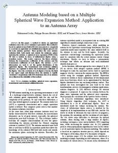
Figure 1.1
Coordinate systems - the cartesian coordinate system
In Section 1.3 some major consequences of introducing the elementary antenna
respectively
approach are discussed. First the so-called effective current concept is in
the unit vectors
- the spherical coordinate system
troduced by using the boundary conditions at the center of a circular aperture
respectively the ur.it vectors
or at the center line of an aperture formed by a parallel-plate waveguide.
(x,y,z)
(i ,i ,i ) -:■: -y -z (F.,y,9)
(i , i , i )
- the cylindrical coordinate system
It is supposed that the boundary conditions are confined to the continuity
respectively the unit vectors
(r,nj,z)
(i ,i,,i )
of the TEM field at the aperture on the axis of the guided structure. The effective current is also used to compute the first-order reflection co The time dependence of the field is assumed to be harmonic with cü where LO is
efficient without taking into account the excitation of higher-order modes. Further, the edge conditions, the coupling of electric surface currents
the radial frequency. The complex
time factor exp(jtot) has been
suppressed
along conducting materials outside the aperture arid the generalized power con cept at the aperture transition are treated in a phenomenological sense. The electromagnetic
field has to fulfil the boundary conditions and Maxwell's
equations everywhere outside the electric current sources with spatial
density
In Section 1.4 computational techniques dealing with the polarization charac J
(i:,y,z;W) as well as outside the magnetic current sources with spatial den
teristics, the pattern summations based on the "array theory" and the direc sity K
tive gain complete this chapter.
( x , y , z ; w ) . Maxwell's equations in h o m o g e n e o u s , isotropic and
linear
media turn out to be jüJE. E '
1.2 Properties of the elementary antenna
3&
Cl, 1) (1. 2)
[e E) =
(1. 3)
Eu H) -
(1. 4)
To arrive at the field distribution at the antenna aperture and its radiation phenomena in the far field it is necessary to have complete knowledge of the radiating electric and magnetic current sources J and K, respectively, or of the tangential field along a closed surface. To describe the place dependence of the electromagnetic field specific coordinate systems, as outlined in Figure 1.1, are selected. 22
3_ 9x
-x
and p and p e m p
This boundary S divides the electromagnetic problem into two parts: the inter
are respectively the electric charges with spatial density
nal problem, in which the field is described within the domain enclosed by S
(x,y, z ;to) and the magnetic charges with spatial density p
(x,y , z ;io) and and the external problem for the field description in the unlimited domain
£(UJ) and u(oj) are the complex permittivity and permeability to include lossy outside S. At S both fields have to be equal and have to fulfil the boundary media. conditions. In vacuum the permittivity e
is 3.854 x 10
[F/m] and the permeability (i
is 4TT x io"7 [H/m].
Alternatively, the fields on S can be replaced by assuming local surface cur
Pointing's vector S, given by the vector product of the electric field E and
rent and surface charge densities. With reference to Figure 1.2 the surface
magnetic field H at a given point P (x,y,z), delivers the power density in P
densities can be written as
and the direction of the power flow. Outside the sources each field component can be found by solving the Helmholtz equation and taking into account the boundary conditions a~ the sources or at a closed surface around the sources. external snace
At the same time the Sommerfeld conditions, which describe the electromagne tic behavior at an infinite distance from the sources, have to be satisfied. It is common practice to use an isotropic radiator for reference purposes bas ed on power considerations. Such a radiator is characterized by a spherical ra
2
diation pattern and a reference gain equal to 1. Figure 1.2
Boundary S with normal unit vector n
With the approach to be followed here however, we need a description of the J s = n x (H - Hj)
(1- 7)
-K = n y (E - E )
tl- 8)
isotropic radiator, which includes polarization effects. The field is suppos ed to be generated by a current point source placed in the origin of the sphe rical coordinate system. In free space the electric field E becomes E (x,y,Zjw) =
E (R;UJ) a
47TE exp (- jk R) /4TTR e =
4TTEX[R) e
pes=
a - 'e252 '
E
PmS
n • (U2H2 - UJHJ)
A)
(1
-
9)
(1. 5)
where
=
d.10)
where the indices 1 and 2 refer to the internal and the external space, res
e is the unit vector characterizing the polarization state of the electric
X{R) is the three-dimensional Green function in free space. The modulus of the
pectively.
If J , K , p and p are the source terms then the equations (1. 7) to S —S eS mS (1.10) describe the boundary conditions at the source. If the source terms are zero the equations express the continuity of the tangential E and H com
complex reference amplitude E [v] is related to the transmitted power P
[V.A]: ponents and the continuity of the normal components of EE and \1U. at the boun
|E|
= /Ü^TT
(l. 6)
dary.
For arbitrary generating structures the boundary conditions at the sources are satisfied by using the vector potential method. Exact solutions derived from the real sources are only known in special cases. Modeling and approximations
part of the boundary S and where the electromagnetic field is constant and
are inevitable, in most cases, and depend on mathematical techniques and on
different from zero. Consequently t
an assumed knowledge of the field at a closed surface S around the sources.
aperture of the elementary antenna.
The radiation characteristics of the elementary antenna are determined cor
p
= n
• EE = 0 on S
(1.13]
rectly if and only if a closed surface S can be defined, along which the electromagnetic field is zero on S
and different from zero for the aperture
S . This means that a discontinuity exists in the field at the contour C
p = n * p H = 0 o n S
(1.14)
The elementary aperture has dimensions Ax and Ay, both small with respect to
around S . The consequences and the physical meaning of this statement will be elucidated by applying specific electromagnetic field integral equations,
wavelength. The field at the aperture S_ is assumed to be Transversal ElectroMagnetic (TEM) with field components
starting from Greens' Theorem in combination with Lorentz' Reciprocity. E = E Returning to the assumption that the above-mentioned closed surface S can be
H=
(OïU) ix
(1.15)
H, [OjWl i. = E
(OjW) Z? 1
[1.16)
constructed for the elementary antenna, the field components at the aperture can be considered as the source of radiation. The source densities (1. 7) to (1.10) will be used to find the equivalent charge and current densities. The surface charge densities (1. 9) and (1. 10) are zero everywhere in a layer with an infinitesimal thickness inside S (belonging to the internal space)
In Appendix I t h e f i e l d E ( P ) , H (P) o u t s i d e 3 i s d e r i v e d u s i n g t h e v e c t o r p o
and in a layer with an infinitesimal thickness outside S (belonging to the
t e n t i a l method. The g e n e r a l r e s u l t s f o r R l a r g e r e l a t i v e t o Ax and Ay a r e
external space). From Eqs. (1. 7) and (1. 8) it is seen that the surface cur rent densities in these layers remain. According to the equivalence principle,
E° (P) =
(jkQ)
E J AX Ay x(R>
[ ( k . - 3jk_R~ -
equivalent sources in the layer just outside S can be introduced, which ren ders the enclosed domain source-free. H° (P) =
IjWU»)"
1
E
Ax Ay X(R)
(kj: - j k R - 1 )
[ (k Q - 3jk Q R""
- 3R~ ) Sin8 c o s * i ( ( 1 + cosO)
i
2
- 3 R " ) sin8 sin*
- (kQ - J^QR" 1 ) t t l + cos9) i
and t h e f a r f i e l d components E° (P) =
jk
E
Ax Ay X(R)
H° (P) =
(i
■■ E° ( P ) )
According to Eqs.
(k
»
(1 + cosC)
1/R, (cos* i g
+ R~
i
- s i n 6 c o s * 1 }]
iR + R"
2
i
- sin6 sin* 1 }]
Fraunhofer region)
(1.19) (1.20)
t h e r a d i a t i o n of t h e e l e m e n t a r y
antenna
i n t h e backward d i r e c t i o n E° (2 ) = p Figure 1.3
Equivalence principle applied to the elementary antenna
(jkj -1 0
(1.18)
become
- sin* i )
zT
(1.17) and (1.18)
(1.17)
(0 = F and R = z ) goes down r a p i d l y a c c o r d i n g P E, Ax Ay X(z ) z~2 i 1 p p -y.
to
This means that in the backward direction only a contribution to the near field is noticeable and that no power transport takes place. It is assumed
With the coordinate systems shown in Figure 1.3 the elementary antenna is po sitioned in the xy plane at the origin. The equivalent sources on 3 for this elementary antenna become ^ x = iz y H £ 0 on S
(the elementary antenna),the contour C included
= 0 on S anywhere else on S
(1,11)
that the effects of this near field on the radiation characteristics can be taken into account by introducing an effective length Az along the negative z-axis. Based on inspection of the behavior of this near field we expect that 2 has to remain finite and therefore Az will be in the same order of
Ax Ay/Az
magnitude as (Ax Ay) , K = -i X E ^ 0 onS. the contour C included = 0 on S1 2G
The negligible far field of the elementary antenna for 6 = F determines the (1.12)
field drical surface going to minus infinity along the negative z axis is selected for S,, and it has the same transversal profile as the aperture S
(Figure 1.4)
at C. Using the r e l a t i o n s
E [P) =
j k 0 ƒƒ E 1 X(R) OS i S
x
+ Zj
S
S
7
- Z ^ V p x ƒƒ S
-
(joiu )
y
é (B • T) X(R) d l
P c
2
and n • E = 0, n • H = 0
become
2
0 j k Q ; j H 2 X(RJ dS i
- VX(W
and (1.22)
■' ƒƒ H2 X(R) dS i
2
+ (jiüEj-1
H (P) =
a
V X(R)
for the elementary antenna Eqs. (1 .21)
E
"
(1.23)
~
j X(R) dS i
x
2
_ 1
7 P
f {E • X) X(R) dT C
d.24)
In accordance with the representation provided by Eqs. (1.23) elementary antenna can be described as follows.
Figure 1.4 Integration
surface
The surface S is closed v i a the sphere Q at infinity. The field at this sphere
give the field
contributions
the following
characteristics
The f i r s t
of two i s o t r o p i c r a d i a t o r s at
E l e c t r i c a l l y i s o t r o p i c r a d i a t o r E. (R) =
Jk0EiS2
X(R)
Magnetically i s o t r o p i c r a d i a t o r H. (R) =
jk-B^XdÖ
and (1.24)
and second
the
integrals
the o r i g i n ,
with
r-
(1-25)
t
(1-26)
does n o t contribute t o the field in point P because o f the Sommerfcld condi tions. The field of the elementary antenna is zero along the cylindrical sur
Both radiators
give the t o t a l
field
E
(R), H
(R), where
face, except for the near field over the length A z . The contribution o f the near field is taken into account by a n artificial enlargement o f S , which
-XS i
may increase the directive gain as well In this w a y the electromagnetic
field along S
-is
(R) =
H.
IR) +
{j(,
-Eo)_
7
* -is
| R )
-1 (R) -
(jüJUQ)
7 * E
(R)
is zero everywhere a n d differ
ent from zero o n S - A more quantitative description o f the elementary
antenna
can b e achieved by using electromagnetic field
integral e q u a t i o n s , starting
from Green's a n d Lorentz' Reciprocity Theorem.
W e limit ourselves to the
boundary conditions o n S
iR) = s
H
(Section 2 . 2 ) .
These isotropic radiators with linear polarization c a n exist under the condi tion that the third integrals in E q s . (1.23) a n d (1.24) are taken into account.
With the concepts o f surface current densities a t contour C w e also assume that
a n d the edge conditions along contour C , which
the scalar vector products in the integrand represent current densities through C having z-comoonents For a non-closed surface S
the electromagnetic
field outside S_ can b e w r i t
ten a s (see Appendix II} E (P) = J/i-jWy (n X H) X{R) + {n * E) * VX(R] + (n - E) 7X(R)ldS S
?
JJ -JjuJG ƒƒ{*> s_
(jiüE)
§ (H • x) V X ( R ) ax
(i.2;
$ (E • T) X(R) dT = £ K X(R) dT c c z
(1.28)
where J
(n * E) X(R) + (n * H) X VX(R) + (n ■ H) 7X(R)^dS
and K
are the z-components
through C o f the electric and magnetic
surface
L
+ (juip)"
1
$ (E • T) VX(R) d l
(1.22)
T is the unit vector along C , a s indicated in Figure
current, respectively. The amplitudes o f the surface current equals J
C 1.3 for the elementary
antenna. The integral along C takes into account the discontinuity 23
(1.27)
"l
H (P) =
only. The contour integrals can then b e written a s
$> (H • T) X(R) dT = j> J X(R) dT C C Z
o f the
K
z
=
H
2 ( i y ' I}
z
-
E
i )
E [d, (E X H
+ E
x H) • n dS
(1.46)
where n i s t h e o u t s i d e normal v e c t o r on S and t h e a s t e r i s k s i n d i c a t e t h e com at the aperture which delivers the polarization of interest, dS
is the aper
p l e x c o n j u g a t e of t h e f i e l d ture area and E
vectors.
(8,(ft) is the polarization dependent far field envelope of the
elementary antenna. The phase of the decomposed field at the aperture is given
In n e a r l y a l l c a s e s a s p h e r e a t i n f i n i t y
i s chosen f o r S and t h e a n t e n n a
l o c a t e d i n t h e c e n t e r of t h e s p h e r e . I n f r e e s p a c e E q . ( 1 . 4 6 ) P
This general case can be simplified if
t= ? - i k
^
n
in the denominator of X (R ) in Eq.(1.44) n
The d e f i n i t i o n of t h e d i r e c t i v e g a i n G
- simple aperture geometries are considered f.e. circular or rectangular aper
n.47)
sphere radius R
- the far field pattern is determined for the whole array, because in that case R can replace R
N 2 a=Bphere
f
is
yields
of an a n t e n n a i s t h e r e l a t i o n between
t h e maximum power d e n s i t y of t h e a n t e n n a and t h e power d e n s i t y of an
isotropic
tures - simple excited fields at the aperture
(amplitude and/or phase) are analyzed.
The advantage of the proposed computational technique is that all antenna p r o blems are primarily based on identical elementary antennas in which each an tenna element satisfies Maxwell's e q u a t i o n s . Reflections and coupling
effects
at the aperture are taken into account by an array of current elements at the 30
antenna under the c o n d i t i o n t h a t P , , S , and Cti be t h e same f o r b o t h a n t sphere t e n n a s . This d e f i n i t i o n r e s u l t s in Gd =
lim
47TR
|E
|
/j$ spherG radius R
Eg.{1.48) is given for transmitting antennas. Based on reciprocity it is found, that for a receiving antenna Chapter 2 OPEN-ENDED WAVEGUIDES This means that for an arbitrary receiving antenna an effective area S be defined depending on frequency, while S,
can ef f is the effective area of the iso-
tropic antenna. Starting from the power density at the receiving antenna, the
2.1 Introduction
received power of the antenna is computed. In Chapter 1 the elementary antenna and the effective current through the con
The quotient of this received power and the received power of the isotropic antenna yields G . d
tour around the elementary antenna have been introduced.
An application of the directive gain computation is given for a TEM aperture
will be demonstrated by using the elementary antenna pattern. The effective
In this chapter pattern computations for cylindrical open-ended waveguides
with physical area S and effective area S'.
S' is determined by using Eqs.
(1. 5) and (1. 6 ) , (1.19) and (1.20) for Q = 0. Vie find for the isotropic
current concept will be used to investigate reflections and the excitation of higher-order modes at the aperture.
radiator( E[v/m], E ^ V / m ] , H^A/mJ, s[m 2 ], S'[n/], A Q [m], R[m] ) Fundamental investigations in the field of open-ended, cylindrical, waveguides :TTV60
have dealt mostly with parallel-plate waveguides excited with different ampli tude and phase distributions. Apart from the Kirchhoff-Huygens vector formula
and f o r t h e TEM a p e r t u r e E (6 = 0) ' ± x =
2jkQ Ej . S' . X(R) B J / G
. E (r;w) ■ e
(1
[13] other methods such as the Geometrical Theory of Diffraction (GTD) [14,15], and specific integral methods [16] have been used and comparisons with compu tational techniques such as Moment Methods [8,17] have been made.
The relation between S' and S becomes B'
=
VG
. >^/4TT . S
{1
In the case of TEM wave propagation in the waveguide comparisons between the where
"elementary antenna" method and the other methods are of interest because the
G
on~axis far field derived from the Kirchhoff-Huygens vector formula is exact,
d C a n b S c a l c u l a t e d when the far field pattern of the TEM aperture is knowr (Section 2.2).
and the same results as achieved by GTD are found v/hen only single diffraction at the edges is taken into account. To make comparisons between theoretical results obtained from the various likely methods, the "elementary antenna" ap proach for open-ended waveguides which, in a planar configuration, allows TEM propagation is described in detail.
Investigations into the single mode patterns of the parallel-plate TEM wave guide, rectangular waveguide feeders carrying TE and TM modes and circular apertures with TE and TM modes are treated in Sections 2.2, 2.3 and 2.4, res pectively. The calculation of the higher-order mode excitation for the above mentioned TEM and rectangular open-ended waveguides, together with their influence on the reflection coefficient at the transition and the radiation patterns, are 41
given in Sections 2.5 and 2.6. Finally, experimental verifications are shown in Section 2.7 in a global w a y , which can be attributed to the that during the actual measurements
circumstance
the different phenomena cannot be sepa
determined, where (2M + 1) &X =
a
(2N + 1) Ay =
b
(2. 3) (2. 4)
rated. To f a c i l i t a t e -
Near
-
Near
-
Far
numerical
field
region
handling
three
regions
I,
where
min{R
II,
where
4X Q < m i n l R ^ l
III,
where
min{p
are
distinguished:
} < 4X Q
2.2. Parallel-plate TEM waveguide
In Figure 2.1 the parallel-plate TEM waveguide is shown. The inside of the
field field
region region
j
< max{4a / X Q ,
> max{4a
/>. , 4 b
4b
/XQJ
/XQ]
walls has infinite electric conductivity. The outside is non conducting. Leak age of the field via the side walls is neglected so that only the
radiation
from the aperture at the end of the waveguide remains. This means that the
In
the
can
near
field
region
be u s e d e v e r y w h e r e ,
the
far
field
except
I
for
P.
pattern
of
the
elementary
antenna
< 4X .
side walls are supposed to b e of the magnetic wall type. In the magnetic wall we have magnetic surface currents and in the parallel-plates we have
electric
On t h e b a s i s
of
computational
and
in
order
to
fulfil
the
conditions
R a n d Ay « P. t h e d i m e n s i o n s Ax Ay o f t h e e l e m e n t a r y a n t e n n a mm mn c h o s e n i n s u c h a w a y t h a t Ax = Ay = 0 . 0 2 5 R for R < 4AQ and Ax = Ay = 0 . 1
We assume a TEM wave incident along the z axis and an aperture positioned in the z = 0 plane
evidence
Ax «
surface currents.
J
Xn U
for
R
> nm
are
4Xn. 0
(Figure 2 . 1 ) . The electric field E ° (P) in p o i n t P due to the radiating elementary antenna -mn at (x,y,z) = (x ,v , 0 ) , in the near field region I, becomes (Eq.(1.17)) m - n E° (P) - mn
- E
Ax Ay X(R ) . 1 mn - jkrt R ) 1[< k_ R * 0 am 0 mn 2 2 (-k„ R + 3jk„ R 0 ran 0 {sin&
(jk„ R 2 ) _ 1 . 0 mn I d + cos9 ) i - stn9 costp i ) - i + on - K mn nm - ; -x +3) ran
cosip i + sinü ran mn - x ran
sin6
mn
simp
cosip mn
i + cosb mn - y ran
i "} ] -z
where M 4X mn 0 E° (P) = -mn
The aperture is divided into a number of equal elementary antennas with dimen sions Ax Ay. in this way the radiation properties of a olanar array consisting
of
equidistant
(2M + 1) . (2N + 1) elementary antennas has to be
whe r e Ax = Ay =
jk„ E, Ax Ay X(R ) R^1 [-(x - x ) R"1 0 1 mn ran p in mn + (y - y ) i + 2 1 } + £R + Z ) l J p n -y p -z mn p -x
J
0.1
L
- x ) i p m -x (X - X ) i 1 p m -z
[(X
(2.
Eq.(2. 6) can also be used in the near field region II. As long as the higher-
When the TEM mode reflection coefficient V
order mode excitation at the aperture can be neglected the radiation pattern
effect on the radiation pattern can be found by using Eqs.(2. 5) to (2. 9)
in regions I and II is found via the near field planar array theory, which
and by replacing
(Eq.(1.40)) is introduced, its
means that H (2. 7)
(P)
->-
-«v
n
*
~Yr
ip
-»
-lp
lp
ran y
where A is dependent on the power distribution and the directive gain of the radiating aperture.
-
TT
e
-IP
In region III the simple far field planar array theory for the rectangular
-) = (9 ,TT/2) and (-6 ,TT/2) , as shown in Figure 2.3. g g
origin each of the two waves has to fulfil the boundary conditions. The rec tangular waveguide problem differs firstly from the parallel-plate TEM wave guide , however, in that the phases of the elementary antennas are no longer constant over the aperture but become a linear function of the y coordinate (k v sinS and k„y sin (-6 ) respectively). 0 g 0 g Secondly, the directions in which the elementary antenna patterns have their maxima are no longer along the z axis, but in the yz plane, they enclose ang les 9 and -6 with the z axis. To determine the radiated far field first the g g pattern of a surface element Ax Ay, situated in the aperture, is calculated. To this end the aperture is divided into a rectangular grid similar to Figure
It
i s assumed
conductivity absorbing the
that
the inside
with negligible
material.
of t h e closed waveguide wall
The a p e r t u r e
thickness of t h i s
and t h a t
h a s an i n f i n i t e the outside
open-ended waveguide
electri
consists
is located
of in
2.1.
m =
z = 0 plane.
T h e TE
field
propagating
E (x,y,z)
-
cos(TTy/b)
H (x,y,z)
=
{6 cos(7Ty/b)
in the positive
z direction
i s given
i^_ e x p ( - j B z ) i ^ + jïï/b
. sinfiry/b)
i j
exp(-jBz)
/
(lop,,)
The coordinates for an arbitrary element (m,n) are given by
(x ,y ,0) = (in Ax, n Ay,0) where -M, -M + 1,
(2.17)
0, . . . , M
by [19] (2.13)
(2M + 1) Ax
(2.14)
(2H + 1) Ay
where caused by element
e = &1 - (ïï/b)2
C
[m,n) becomes
P T E 2 iP)
> - i n
mn
In terms of the decomposed components the total field is written E -
lP
(2 1(
°'
-mn
-
'
m n
whe r e
E, + E„
(2.15) (2.16)
0,1 0,2 E (P) a n d E (P) o r i g i n a t e -irm -mn tively. 0 1 -mn l P )
whe re E1 =
0 . 5 exp [-jit
{y s i n { - 6
H, -1 E2 =
0 . 5 e x p [ - j k r {y s i n ( - 6 ) + z c o s ( - f i ) } ] (cosH i 0 J g g g -y 0 . 5 e x p [ - j k {y s i n (6 ) + z c o s (fl ) } ] i
H. = -2
0.5 exp [.-jk. {y sin (9 ) + z cos (6 )}] (cose i 0 g g " g -y
It =
c a n b e shown
°'
5 jk
n
(R
tim ]
A
from
the plane
waves
E , , H, a n d E „ , H „ , - 1 - 1 -2 -2
"
Ay
COs9
n
e x p(
^Cl"
&Y s i n Ö
1 a
ü(-6fl»ir/2J
) + z cos)
citation : E(9, "'pq '0 ' r
- k
2
4 plane
- } , { - & , $ ) , (0 , - ) a n d 9 9 g g g g cos9 = 3 /kand cosé = pïï/(ak ) g pq c g pq
0
g -x [cos$
cosy- + s i n y
g -z
Siny)
+ cosO
cos9
(7 3A1 U.J4J
waves w i t h
( 0 , 0 ) g g
g
{l + sinG s i n B
0
where
specific
propagation transmission ed.
Since,
and
reflection
however,
coefficients
experimental
at
the
verifications
aperture in
Section
have 2.7
t o be are
consider
shown
for
the
TE
-mode o n l y ,
this
will
not
be worked o u t
further. n/p.Jn(p)
[Jn-l'P)
=
|
=
i —
ïï
471
2.4
Circular
waveguide with
TE
or
TM m o d e
excitation
+
f J iexpi 0 !■
J
jp sin O
exp(-jp sin O J ' (p) =
■? iJn_xU->)
=
— ƒ {expf 4
IT
J
~
Figure
2.6
To c o m p u t e we b e g i n
Geometry of
the
by
radiation
-modes i n s i d e mn c r i b e d by [19] =
J
(p)
. sin(ntp)
open-ended
pattern
characterising
F o r TE
H
the
the
of
open-ended
field
a circular
circular
inside
w a v e ga u i d e
the with
waveguide
circular
j p s i n c)
waveguides
(Figure
2,6)
a the
can be
des-
E
=
0 k0/S
Hr =
-jB/kc
.J;(P)
i n (nip)
. exp(-jBz) ,
-kn/B
where {k
n " (P™,/"»
r o o t of
As w i t h
the
aperture
the
Be s s e l (p) =
-
3 J
parallel-plate
the
J
)
J'(p)
at
z = 0 into
functions
are
(p)/dp
waveguide
and the
a number of
written
for
TE
elementary
we w a n t t o
antennas.
With t h i s
divide in
s x p ( - j 8 z - jnip - j p s i n C + j n
) =
e x p ( - j 6 z + jntp - j p s i n g + i n £)
-
+ s i n ( p s i n Q)
1/2TT ƒ ï e x p ( j p s i n C)
( c o s n£ - j s i n n£) +
exp(-j6z the
to
each p o i n t
E
H
sinfn^fd;
T h e TEM f i e l d . sinC i j
+ B/k
. cos^ i
-jk/ 0
E
-jk
coordinates.
coordinates
2 / 4TTk 4TTk
Z /
to
express
. { c o s ( - - ip) i
4nk
" j k . / 4TTk O c
E3 =
-jk
=
j
~ V
For p r a c t i c a l
. {COB[L,
. {g/k
(
c ' ~
- j k Q 2 . / 4ïïk "jko/
4ïïk
Eqs.(2.43)
to
E , H
the
terms
superposition
- (p) i
3/
V
SiniK
+ tP)
exptjt ) + i j
exptjt^
reasons,
(2.47)
however,
we p j t e f e r
exptjtj)
c
'
. { c o s t ; ; + ip) i {_B/k
(2.51)
- s i n t C - lp) i ]
o'
s l n (
'
+
represent
+ s i n t C + /Ur
>/£ r
3.4 Results of a C band dielectric
(Appendix X I ) .
radiator
Based on the knowledge obtained from previous sections we have designed a d i electric filled TEM waveguide radiator. The TE square waveguide
" I)}
tilled TEK waveguide
the
(-■■ -')
lystyrene
(e
(inner dimensions
p a r t of the radiator is a
27 ■■'■ 27 mm) filled with the dielectric p o
= 2 . 5 5 ) . The center frequency f
of this TEM radiator will t h e r e -
fore be around 5 G H z . The matching of the aperture at the end of the parallel-plates will be done Two parallel-plates with a length of 28 mm were mounted in front of the TEM in a more generalized sense because we use the same approach for the TEM a n aperture in a way similar to that shown in Figure 3.10, in which the tenna in Section
dielectric
3.4 and for the TE .-mode antennas in Chapter 4. ends at AC.
The matching network at the aperture will be described by its scattering matrix. When a short circuit is mounted at AC v/e obtain a reflection phase as shown in In Appendix XII it is shown that for matching the scattering coefficient
S^0 Figure 3.16. At f
of the matching network is the complex conjugate of the aperture
= 4.95
GHz we expect arg
[V
) = 0 degrees. The
wall thickness of 2.5 mm partly explaines the measured arg
82
waveguide
reflection. (T
) of 11 degrees.
According to Eq.(3. 5) the dielectric filled waveguide is matched to the empty
Figure 3.18 shows that the mirror affects [T
parallel-plate TEH waveguide by using a dielectric sheet of polystyrene with
mirror forces the field to stay inside the plates. This can also be concluded from Figure 3.19, in which the results of |T
a 3 mm thickness and mounted at a distance of 5 mm from AC.
j , mainly in the sense that the
] are given in the case in which
the ends of the parallel-plates are short circuited. To find the optimum distance for a selected 3 mm thickness of the sheet T measurements of this radiator with open-ended parallel-plates were made with out a mirror and for distances from the plane AC of 4, 5, 6 and 7 mm. We see in Figure 3.17 that up to f
4.95 GHz arg [T
) becomes independent
of the sheet distance and for a constant phase gradient with low jP
I a dis
tance of 6 mm appears to give an improvement.
4.5 Figure 3.18
GHz
5.0 T
5.5
4.5
GHz 50
55
as a function of frequency of the dielectric filled TEM
waveguide radiator (27 •■' 44 mm) with (1) and without (2) a mirror of length 20 mm.
45 Figure 3.16 arg (f
50
5.5
1
) as a function o f frequency o f the dielectric filled -
TEM waveguide radiator
■
■
(27 X 44 mm) when a short circuit is
5 6 7 .
'
a. magnitude,
b. phase
' a :
.
mounted at AC
-40 1.5 Figure 3.19 | T
5.0
5.5
4.5
5.0
GHz 5.5
j as a function of frequency with (a) and without (b)
a mirror when the TEM waveguide radiator is short circuit ed at the end of the parallel-plates. Positions o f the matching sheet (thickness 3 mm) of
The fact that \T Figure 3.17
V
as a function of frequency of the dielectric filled TEM
\ is different from 100 percent already indicates a consi
derable leakage via the side walls over a length of only X/2 due to the small
waveguide radiator when the matching sheet of 3 mm thickness
size
is placed at
Therefore, we have reduced the length of the plates to 9 mm, just behind the
plates 28 mm,
84
5, 6 and 7 mm
4, 5, 6 and 7 m m from the plane A C , parallela. magnitude,
b . phase
of the radiator.
sheet placed at 6 mm from A C .
The two p a r a l l e l - p l a t e s and the 20 mm mirror can be seen in Figure 3.20
diverging
(as discussed in relation to Figure
network which gives a reflection nitude
for S
3.19) we have selected a matching
so large that at the aperture the desired
remains. When we place the dielectric
sheet
at
front of the TEM aperture we find for the aperture reflection to this matching sheet T'
waveguide wall thickness - 2 5 mm
= 0.13
exp(+j
mag
19 mm in
F' transformed
118°).
plate thickness = 5.0 mm For the matching sheet we select a dielectric With c
mirror thickness = 2.5 mrr
=10.2
and a thickness
of 1.0 mm, mounted by using a low density dielectric foam. For Eq.(3. 6) we
TEM aperture = 27 x (A mm fr = I 9b GHz
Taking into account a 40 p e r c e n t contribution to the aperture plane as an Figure 3.20
Dielectric filled TEM waveguide
average over the frequency band a theoretically optimum match is expected.
radiator
In Figure 3.22 In Figure 3.21 the reflection coefficient T
measured at plane AD is shown.
For reference the measured magnitude and phase of the reflection
the result for this network
shows a VSWR less than
1.1
over
a 20 percent bandwidth.
coefficient 360
is given in the same figure for the case in which a short circuit is mounted
b j
deg
directly behind the dielectric sheet.
. with \
180 a
2
0
360 I.
— >
b^
deg -10
■
—-^without
-
1
180
20
Figure 3.22
30
Figure 3.21
5.0 I"
5.5
(—)
[V)
5 0
GHz
The effects of the external matching network on the patterns are demonstrated by the E plane patterns of Figure 3.23a and the H plane patterns of Figure 3.23b.
5 5
,
a 2 . magnitude, b 2 . phase of
when a short circuit is used at 9 mm from AC. computed, E q . ( 3 .
The computed results for f of arg
45
of the dielectric filled TEM radiator of Figure 3.20
al. magnitude, b l . phase of V T
1)
- 4.95 GHz are also indicated. From the
gradient
relative to the same gradient for the short circuit we de ri ve
that an external match is needed at about a quarter wavelength
(= 15 mm) in
front of the aperture. Bearing in mind that the reflected power from an external matching network
86
3.20
-180
GHz 4.5
F of the dielectric filled TEM radiator of Figure AD without and with matching network
is
29 x 58 mm and is only 10 percent less than the optimum gain calculated by using Eq.(1.48).
In the H plane patterns some influence of the edge C is still seen, mainly for frequencies higher than f . This is caused by the fact that the nonuniform field just outside AC is different from zero for frequencies above f (Appendix X ) . c In the E plane patterns wc sec a superposition of the aperture field and a disturbing field caused by the mirror which does not coincide with the aper ture plane and by the finite plate thickness with inherent r.f. current con tributions .
Figure 3.23
Measured r e l a t i v e p a t t e r n s without (1) and with (2) matching of the radiator of Figure 3.20. a. E plane, b. H plane. 1.1 and 2.1 Frequency 5 GHz co- and cross-polar patterns 1.2 and 2.2 Frequencies; 4 . 5 , 5.5 GHz co-polar patterns
I t turns out that the patterns are not strongly dependent on frequency and that the external matching network negligibly influences the p a t t e r n s . In t h i s way a low-cost matching is obtained for the TEM r a d i a t o r . The gain i s equal to that of an open-ended TE waveguide radiator with dimensions of 88
Chapter 4 SMALL TE„
RADIATORS WITH A RECTANGULAR CROSS
SECTION
4. 1 Introduction
As was investigated in Section 3.3
the use of a dielectric transition
at the
aperture makes it possible to reduce the dimensions of the rectangular w a v e guide under half a wavelength. Small waveguide radiators can be applied,
for
example, as radiating elements in hybrid reflector arrays to realize multiple spot b e a m s , as will be demonstrated in Chapter 5.
In this chapter the central theme is the development of a single
radiating
If we cut the square waveguide of Section 3.4 under an angle of 90 degrees instead of 45 degrees
(i.e. perpendicular to the z axis as shown in Figure
the two plane waves corresponding to the TE
-mode may even have
4.1)
complete
reflection.
"2 =1
0
"J
2b>/E~
z a = b = 27 m m
-* y
Figure 4.1
Top view of the TE
dielectric filled square waveguide
with the transition of the dielectric to free space c o inciding with the aperture plane
For this geometry the reflection coefficient
(Section 4 . 2 ) , radiation pattern
(Section 4 . 3 ) , matching technique for aperture and coax-waveguide adapter
(Sec
tion 4.4) are analyzed. The aperture matching, needed to compensate the high reflections of such small radiators, and the radiation patterns in particular indicate that the approach presented here can be used in a wide variety of array configurations.
91
In this chapter the aim is to design a radiator with square cross section
the transition to the aperture is determined by the condition that the trans
(Figure 4.1) and with the following performance:
mitted field, which is decaying exponentially with distance must be negligible
- center frequency 4.2 GHz
at the aperture. When this is not the case, especially when a dielectric tran
- VSWR less than 1.3 from 3.85 - 4.5 GHz
sition is at the aperture or in front of it, the phenomena have to be describ
- transversal size less than 0.4A
ed in a different way.
- dual polarization capabilities - patterns with good rotational symmetry
Let us consider the situation in which the transition coincides with the aper
- high efficiency
ture, as is illustrated in Figure 4.1. The S matrix coefficients of the tran sition are then given by
Furthermore, attention is paid to different matching configurations near the aperture plane. In this chapter no attempts are
works to obtain optimum wideband matching but mainly to satisfy the require ments using
sn=
rfc = (B, - B 0 ) / ( B , * S Q )
-s22=
made to realize matching net S.„ ■
S„, -
(1 - S2 )
h
(4. 2
cheap networks v/hich are easy to fabricate. In this way it is
similar to the approach presented in Section 3.4 for the matching of TEM wave for E sin 6 < 1
k. (1 - e si.
guide radiators. The aperture reflection itself is determined in the next Section.
-3k.
(E sin 9 - I)*
for e
sin
A special role is played by the two coax-waveguide adapters, each of which is used for linear polarization. To design a low reflection device for coax-wave
We characterize the aperture reflection for z = Az
guide adapters with an arbitrary cylindrical cross section an approach based
Figure 4.2 the relations between incoming and reflected waves become
( Az -+■ +0 ) by V . With
on experimental specification of a three-port network with prescribed require 11
12
2' 1
ments is chosen.
VAi 4.2 Aperture reflections of the TE
radiator with a square cross section
Before computing the aperture reflection of the radiator shown in Figure 4.1, we give the reflection coefficient T
due to the transition from the medium
with a relative dielectric constant e
to a medium with £ r
We f i n d (Appendix X) T t = (cosS - (e _ 1 - sin 2 G )h}/{cosd + ( £ _ 1 - sin2fc) fy g r g g r g 2 = {cosü + j (sin 6 - e~ K}/{cos6 - j ( s i n 6 - e ' V } g g r g g r
h-
m
- 1. r
sin 2 9 < 1 r g for e sin 2 6 > 1 r g for £
We limit ourselves to cases in which complete reflection occurs when 2 £ sin 6 > 1. r g We also measure this reflection coefficient when the transition is inside the waveguide and far enough away from the aperture. The required distance from 92
B,
(4.
Figure 4.2
3tr-1
BT
S matrix representation of the transition of dielectric media with E
and r
2
£
=1
For t h e r e f l e c t i o n
coefficient
Tof
t h e combined a p e r t u r e and t r a n s i t i o n
f l e c t i o n we f i n d by u s i n g E q s . ( 4 . 2) and (4. 3) r -
B 1 /fi 1 = s
2
+ s l2
a
a
r / U - s22 r ) =
fc
/u + r
__x-
fc
a
r )
IA. A)
"
"
without
tion coincides with the aperture at
Due to the propagation angles + 0
;
with
■
-
inside the dielectric the two plane waves
are completely reflected at the transition. Therefore, a reflection coeffi cient F averaged over the interval 0 < x < b cosO
180 deg
is introduced, i.e. g
a c c o r d i n g t o a minimum of t h e modulus minim' T
\T (k b /2) - T\.
An a p p r o x i m a t i o n
■ b2 ■
-
■ 6 ■
'P- ■
for
■
:V
i s found by u s i n g
From t h e s e c a l c u l a t i o n s we s e e t h a t t h i s r e f l e c t i o n r e l a t i v e t o t h e r e f l e c t i o n d e r i v e d from T [ k „ / e O r
i_o
: - —
b cosU g F = lb cos6 ) ƒ r=Ck_x/2) dx T h i s a v e r a g e d r e f l e c t i o n h a s been u s e d t o d e t e r m i n e an e f f e c t i v e w i d t h b
Y
is highly
dominant
b Cos8 /2) . g 6
d :
160 deg
" ■ ' ■ "
c2:
This means that extending the dielectric a certain length outside the wave 48
guide will mainly change the phase of the reflection coefficient. This pro
——-9-L._ "
3,2
perty can be put to good use when broad band matching of such small radiators
Jn e
0 3.2
is required.
_ s" .
The aperture reflections are analyzed by using the measurement technique dis
^^
cussed in Appendix VIII. He have measured the aperture reflections of the ra
■ 6 ■
diator of Figure 4.1 as given in Figure 4.3a. In the same figure we have in dicated the theoretical results according to Eqs.(4. 4) and (4. 5). In these
Figure 4.3
Aperture reflection of the dual polarization TE Q 1 radiator
measurements the dielectric transition coincides with the plane z = 0.
With a square cross section (27 ■■: 27 mm) , filled with
The two amplitude and two phase curves illustrate the influence of absorbing
dielectric, reference plane z - 0
material around the outer surface of the waveguide. The main effect of the
a. length of dielectric outside waveguide z
0 mm,
2.55,
absorbers is found in the reflection magnitude. From Appendix XII we know that al. magnitude, a2. phase, x computed results at 4 GHz for matching purposes the phase criterion is dominant.
With this in mind we have derived that, after matching based on an optimum phase, the wideband performance can be adjusted by using lossy materials or chokes at the outer surface of the waveguide structure.
b. z = 0.6, 12 and 24 mm, c = 2.55, bl. magnitude, b2. phase d r c. z - 0 , 1.6, 3 . 2 , 4 . 8 and 6 . 0 mm, i n s i d e t h e waveguide E = 2.55 r d and outside £ = 5 r cl. magnitude, c2. phase
As will be seen in Section 4.3 the pattern of this 4 GHz radiator is not influ enced greatly when the dielectric sticks out for a length z
E (0,tp=o)
-
A 3i(k_a sind/2)
(l + cos0)/2
E {6,ip=ïï/2) = A cos(k Q b siny/2)
(1 + cos9)/2
less than 15 mm,
Its effects on the reflection coefficient are shown in Fiaure 4.3b. For the
(4. 6)
first couple of mm that the dielectric lies outside the end of the waveguide
where A i s computed v i a t h e d i r e c t i v e g a i n c o m p u t a t i o n d e s c r i b e d i n S e c t i o n
the reflection phase changes rapidly and the reflection magnitude slowly de
1.A and i d e a l m a t c h i n g i s
assumed.
creases as was expected. This offers the possibility to use dielectric ex As has been s u g g e s t e d i n S e c t i o n 2 . 6 , t h e e f f e c t i v e w i d t h b
tensions for matching purposes.
For z = 6 mm a small frequency dependance of the reflection phase remains while the reflection magnitude is reduced to around 0.3 for frequencies above
between t h e ef f l i n e s o u r c e s f o r such s m a l l r a d i a t o r s w i l l be l e s s t h a n b . T h e r e f o r e , t h e s u b s t i t u t i o n of b i n E q . ( 4 . 6) i s assumed h e r e . The v a l u e of b is derived err eff
4 GHz. Below 4 GHz the waveguide is near cut-off and a different behavior,
from t h e measured H p l a n e p a t t e r n s .
which has not been further investigated, is noticeable. Furthermore, when
From t h e p r e v i o u s s e c t i o n and E q . ( 4 , 6) i t may be c o n c l u d e d t h a t t h e s e
z ,= 12 mm the reflection magnitude for frequencies above 4 GHz undergoes even
r a d i a t o r s have h i g h e f f i c i e n c y ,
minor changes in comparison to the case for z - 6 mm, while the reflection
t i o n c o e f f i c i e n t w i t h minor f r e q u e n c y d e p e n d e n c e . The d i s a d v a n t a g e ,
phase is reduced an additional 50 degrees.
i s t h e h i g h e r magnitude of t h e r e f l e c t i o n glect the r e f l e c t i o n
We have also investigated the aperture reflection in the case in which a di electric with a higher dielectric constant {;-: = 5) but with the same cross section is put in front of the radiator of Figure 4.1. In so doing, we obtain ed the results depicted in Figure 4.3c. Here we also see that lengths up to 6 mm can reduce the reflected phase at
coefficient
small
d u a l p o l a r i z a t i o n c a p a b i l i t i e s and a r e f l e c
V
coefficient.
however,
For e x a m p l e , i f we n e
and t h e e x c i t a t i o n of h i g h e r - o r d e r TM
modes, b o t h due t o t h e f i n i t e h e i g h t a , and we f u r t h e r c o n s i d e r a = b = 27 mm, £ = 4 GHz and £
= 2 . 5 5 , we f i n d a c c o r d i n g t o E q . ( 4 . 4) t h a t V
= 0.4
exp(j60°).
This means t h a t t h e magnitude of t h e r e f l e c t i o n h a s t o be r e d u c e d
considerably
by means of a m a t c h i n g n e t w o r k so t h a t t h e VSWR r e q u i r e m e n t can be
satisfied
(Section
4.4).
4 GHz over nearly 180 degrees, while for frequencies above 4 GHz the reflec
To s u p p o r t t h e a s s u m p t i o n t h a t t h e r a d i a t i o n c h a r a c t e r i s t i c s of
tion magnitudes change less than 0.12. Near the cut-off frequency the reflec
waveguides f i l l e d w i t h d i e l e c t r i c a r e d e t e r m i n e d p r i m a r i l y by two l i n e
tion magnitude is
we g i v e p a t t e r n s measured i n t h e X-band of two o p e n - e n d e d r e c t a n g u l a r wave
also strongly affected.
rectangular sources,
g u i d e s I and I I w i t h a and b d i m e n s i o n s of 10 mm and 27 mm f o r t h e f i r s t
one
and 4 mm and 10 mm f o r t h e second o n e . 4.3 Radiation characteristics of TE
radiators with rectangular cross section
The r a d i a t i o n p a t t e r n s of t h e o p e n - e n d e d waveguide I were measured u n d e r 3 conditions:
1. empty w a v e g u i d e , 2 . d i e l e c t r i c f i l l e d waveguide w i t h £
( R e x o l i t e ) , 3 . waveguide f i l l e d w i t h d i e l e c t r i c foam (e
= 2.53
=1.3).
Under the circumstar.ee of complete reflection at the transition as described in the previous section the radiation characteristics of the radiator of Fi gure 4.1 are assumed to come from the line sources at the edges at y = + b/2, as introduced in Section 2.6.
Due t o t h e s m a l l r e l a t i v e - t o - w a v e l e n g t h d i m e n s i o n s of o p e n - e n d e d waveguide t h e p a t t e r n s of t h i s r a d i a t o r a r e o n l y g i v e n when t h e waveguide i s f i l l e d
R e x o l i t e . Having t h i s d i e l e c t r i c i n s i d e t h e waveguide i t r e s u l t s in a c u t - o f f frequency of 9.4 GHz f o r waveguide
Higher-order mode excitation due to the finite dimensions is
neglected. The
radiation pattern is therefore the pattern of two linear arrays with length a positioned at y = +_b/2.
II with
These arrays consist of elementary antennas having
II.
For t h e s e waveguide r a d i a t o r s o n l y r e l a t i v e p a t t e r n s a r e shown, i . e . mum of t h e p a t t e r n i s l o c a t e d a t 0 dB. I n t h i s way t h e d i f f e r e n c e s i n s e r t i o n l o s s i n t h e measurement s e t u p a r e
t h e maxi
in the
eliminated.
their maxima at 6 = 0 (Section 2.6). The E and H plane patterns become
96
97
In Figure are
4 . 4 a and 4 . 4 b
shown f o r
t e r n s of t h e which t h e to
9,
10 and
dielectric
dielectric
4 . 4 b show t h a t
minor e f f e c t s
t h e E and H p l a n e p a t t e r n s
of
11 GHz. I n F i g u r e
10 GHz, E and H p l a n e
filled
waveguide
transition
a dielectric
on t h e p a t t e r n s
is
at
filling and t h a t
4.4c 1-2
the
is
given
t h e end of of
t h e empty w a v e g u i d e
under t h e
the waveguide.
t h e waveguide
1-1 pat
condition Figures
4.4a
up t o z = 0 h a s
only
the p a t t e r n s
narrow s l i g h t l y
with
i n s u c h a way t h a t
no h i g h e r - o r d e r
modes
■ b -
in
9
11 '■
io^y 1
fre
ii - '
quency . 1
Because
the
dielectric
e x c i t e d by t h e
i s placed
dielectric
t h i s means t h a t
waveguide e n d b r i n g s b a c k t h e
incident
the
dielectric
aperture
field
transition
at
to the aperture
I
1
are
-90
i
-45
the field
of t h e empty w a v e g u i d e .
Figure
4 . 4 d shows
filled
with
10 GHz E p l a n e p a t t e r n s
a dielectric
poly-urethane
of
foam
t h e open-ended waveguide (e
= 1.3).
The
1-3
measurements
r have been done in such a way that the foam sticks o u t for Z,= 0 mm, 8 mm, 26 mm and 43 mm in front of the aperture. The rectangular cross section of the dielectric inside and outside the waveguide is the same. For a length up to 8 m m the pattern looks similar to that of the empty waveguide. e -j
dB 0
For larger length the E plane beam width is gradually reduced. The examples for
E^--^
z = 26 m m and 43 mm indicate that not only the front o f the dielectric at the whole dielectric outside the w a v e g u i d e , including the sidcwalls
-10
contribute to the pattern. The result can be considered quantitatively by near
-20
z = zwbut
SH
■
field computations of the open-ended waveguide where both the internal and e x
j
-30 ternal regions are filled with
dielectric. •
I
I
The near field is calculated at the surface of the dielectric body outside the waveguide. When the boundary conditions at this surface are taken into
account Figure 4.4
the near field just outside the dielectric gives the equivalent sources need
Relative power patterns of waveguides 1-1 ( E = 1 ) , 1-2 (e = 2.53) r r 1-3 (e = 1 . 3 ) with cross section 10 X 27 mm and waveguide
ed to compute the far field. This approach is similar to the one described II elsewhere for dielectric antennas with rotational symmetry fore n o t considered
[ 2 0 ] , and is there
further.
In Figure 4.4e the 10 G H z E and H plane patterns o f waveguide II are shown when the dielectric with £
= 2 , 5 3 ends at the aperture. The waveguide
dimen
sions and the dielectric transition at the aperture result in the situation in which there are two plane w a v e s , corresponding to the T E which give complete reflection at the transition. 96
(e = 2.53) with cross section r
1-1 Frequency 9, 10, 11 GHz
waveguide m o d e ,
a. E p l a n e ,
4 x 10 m m b . H plane
1-2 Frequency
10 GHz
c. E and H plane
1-3 Frequency
10 GHz
d. H p l a n e , z
II
10 GHz
e. E and H plane
Frequency
f.
= 0, 8, 26 and 43 mm
computed E and H p l a n e s , a = 0.133A
0
b
J c
ef f
= 0.8b
6
= 70 g
:
The t h e o r e t i c a l p a t t e r n s , described by Eg.(4. 6) for 6 = 7 0 g
and b e f f e
The B plane patterns for the frequencies
3.6, 4.0, 4.4 and 4.8 GHz are given
in Figure 4.5b. From Figure 4.5 we conclude that the patterns show a small
are given in Figure 4.4f. Comparisons between theory and experiment reveal
asymmetry in the E and H planes and that the patterns are slightly dependent
that the assumption that higher-order mode excitation in the transmitted field
on frequency. This type of radiator with a transversal size of less than
can be neglected is justified and that the pattern can be determined by two
0.4X
line sources at y = + b ,-/2. — eff
arrays.
These properties have been used for the 4 GHz dual polarization TE
radiator
with a square cross section filled with polystyrene as introduced in Section 4.1. Moreover, for this radiator the pattern is primarily determined by the two line sources. The measured 4 GHz E and H plane patterns of this radiator combined with the theoretical patterns (Eqs.(4. 6 ) , with 6
x
0.4X
will be used in Chapter 5 as a feed element for hybrid reflector
There are no noticeable differences between the original patterns and pattern measurements taken when the dielectric sticks out for 15 mm with the same cross section as the inner wavequide. The measurements of the open-ended wave guide II and the square radiator illustrate the broad validity of Eq.(4. 6) for waveguide radiators filled with dielectric, where the empty waveguide is below cut-off.
'
:
: /
I
:
^
Computed e l e v a t i o n power p a t t e r n s of a 3 m e t e r p a r a b o l i c
where
tor
p(6') = 0.5 D/(l - cos6') is the distance between the focal point and the
several vertical distances
reflector surface.
and i n t h e xz p l a n e , F/D = 0 . 2 5 ,
reflec
fed by an e l e m e n t a r y a n t e n n a p l a c e d in t h e f o c a l p l a n e q = f. = 4 GHz
at
In Figure 5.2 we show the 4 GHz patterns for q = 0, -AQ/3, -A Q /4, -3XQ/8, -AQ/2 and-5X_/8; D = 3 meter and F/D = 0.25.
Based on these results we conclude that for limited beam switching capabili ties : - the spacing has to be less than \ /2 in order to realize angle variations of less than 1 degree - the minimum number of elements is 3, i.e. one element above and one below metal sheet polarization dependent reflector 2
the focus - low side lobes are required for the center element only. Figure 5.3 The requirements needed can be satisfied by the TE
Dual polarized TE
metal sheet polarization dependent reflector 1
radiator with a square cross section
waveguide radiating ele
ments with square cross sections that were described in Chapter 4. Since, for
A second modification is the length A
the application of multipath fading reduction the reflector has to be illumi
ed to 10 mm. These shortened metal sheets were introduced after analysis of
nated most of the time by a symmetrical pattern, a 5-element system was se
the reflection peak at 4.1 GHz (Figure 4.20) measured at adapter 2, when the
lected. Two elements placed along the y axis are dummies and the two elements
length of the metal sheet is 32.2 mm. The experimental work revealed that
along the x axis are used for beam switching.
shortening of the sheets results in a shift of the peak to higher frequencies For a length A
The optimization of the elements is worked out in Section 5.2, whereas the
of the metal sheets which are shorten
= 10 mm, no peaks in the reflection magnitudes are obtained
in the frequency band up to 5 GHz.
system performance for the 5-element array is described in Section 5.3. Atten tion is paid to the VSWR, the mutual coupling and the radiation patterns.
A last modification concerns the coaxial cables to the adapters. Because the
The experimental results obtained with a 3 meter parabolic dish with F/D = 0 . 3
5 radiators have a mutual spacing of about half the free space wavelength it
are shown in Section 5.4.
is necessary to have sharp bends close to the adapter. These bends have been attained by using semi-rigid 50 fl coaxial cables which are bent only once. Reflection measurements of these sharp bends in a semi-rigid cable indicate
5.2 Optimization of dual polarized TE
radiators with a square cross section
that there are no noticeable contributions to the reflection as long as the radius of curvature of the inner conductor is larger than 5 mm. Both semi
In this section the development of five antenna elements is described. Exten
rigid cables are mounted on the outside of the square waveguide and have a
sive use is made of the knowledge gained in Chapter 4. The construction of the
length sufficient tc be accessible for experiments.
elements has been derived from the prototype radiator of Figure 4.19. The individual radiators were optimized by making approximate choices of the In Figure 5.3 the cross section of one element is shown. A comparison with the
length A
prototype TE
for the corresponding polarization) and of the depths Z
radiator described in Section 4.5 indicates some modifications.
Firstly, the dielectric reflector used for coax waveguide adapter 2 has been
(i.e. the effective distance from the probe to the waveguide short of the probes, which
have a diameter of 1.8 mm.
replaced by a metal sheet polarization dependent reflector rotated over 90 degrees with respect to the one for adapter 1. The main reason for doing this
The reflection magnitudes for adapter 1 with H
is to obtain optimization techniques, which are identical for both polariza
5.4a with A_ as parameter.
= 9 . 8 mm are shown in Figure
tions. 120
121
Moreover the isolated patterns of all five radiators are in good agreement with the patterns of Section 4.3. Typical E and H plane patterns for both po larizations are shown in Figures 5.6a to 5.6d at a frequency of 4 GHz.
Figure 5.4
Reflection magnitude as a function of frequency measured at port 1. a. Probe lenrth
= 9.8 mm. Polarization dependent metal sheet P reflector at A 0 = 10.4, 11.4 and 12.4 mm. b. A, = 10.4 mm, £ = 9.55, 10.05 and 10.55 mm 2 P From Figure 5.4a we conclude that a length A_ shorter than 12.4 mm, as found for the prototype radiator yields better results. For A,. = 10.4 mm and diffe rent probe depths £
we have the measurements given in Figure 5.4b, in Which
the combination 9. - 10.05 mm (in the prototype 9, = 9 . 5 mm) and A = 10.0 mm P P 2 has been selected for all radiators. By following the same approach for adapter 2, we get similar results, except
Figure 5.6
Typical co- and cross-polar patterns (relative power) of the
that A 9 is slightly different.
dual polarized TE
The reflection characterization of all five radiators as a function of fre
Frequency 4 GHz, "1" - adapter 1, "2" = adapter 2.
radiator with a square cross section.
quency look very similar. A typical result is shown in Figure 5,5, where the
a.
co-polar H plane "1", cross-polar E plane "2"
VSWR is less than 1.3 over the frequency band 3.8 - 4.4 GHz.
b.
co-polar E plane "2",
c.
co-polar E plane "1", cross-polar H plane "2"
d.
co-polar H plane "2",
0
cross-polar H plane "1"
cross-polar E plane "1"
dB -10
In this figure the relative signal power at 4 GHz is indicated along the ver
-20
pared, while the gain at 0 = 0 is determined by comparison with the open-ended
tical axis, which enables the patterns of the different radiators to be com
rectangular waveguide with a gain as calculated in Section 2.6 (Eq. (2.83)) . -30 ~40 L_ 3.6
4 3
GHz
50
To get rid of the surface currents on the outside of the square waveguides ab sorbing material has to be applied carefully. These currents can cause inter
Figure 5.5
Typical reflection magnitude of the dual polarized TE_, radiator with a square cross section as function of frequency
122
ference-like co-polar patterns and non-symmetrical cross-polar patterns due to a possible non-symmetrical coverage with absorbers on the outside. 123
As can be seen in Figure 5.6 the patterns are still affected by the surface
As far as coupling between two ports is concerned we have measured the coupling
currents. In the array environment we have only considered solutions based on
between ports which belong to the same radiator and between ports which belong
the use of absorbing materials.
to different radiators. For this purpose the coupling coefficients are number ed according to the numbering of the radiators I to V, as indicated in Figure 5.7.
5.3 System performance of the five-element array During the measurements use was made of symmetries. As has already been men-r tioned in the previous section the patterns are influenced by the currents on
The array configuration is sketched in Figure 5.7.
the outside of the waveguide. Therefore, the array has been measured in the polarization 2
polarization 1
different stages of construction. The first and last stages are shown in Figure 5.S and 5.9.
m,
L
Figure 5.7
27
.
Y
m |27
__ —
'
Y
■ i h [-. 2 7 , . | h | . 2 7 . I
Array of five dual polarized TE
radiators with square cross-
sections (inner dimensions 2 7 /• 2 7 mm) . Distance h between the individual apertures includes two times the wall thickness of the waveguide (2 x 1.75 mm)
The five radiators are mounted in such a way that all adapters 1 correspond
Figure 5.8
to the same polarization state (polarization 1) and all adapters 2 to polari
Photograph of the five-element array -without cover- consisting of dual polarized TE
radiators (1st stage)
zation 2. The spacing between the elements is chosen to be half a wavelength at 4 GHz, which means that h = 10 mm. In that case vertical beam switching by using one out of three radiators along the X axis in the configuration of Figure 5.1 will result in sharp gra dients around 0 degrees in the "elevated beams" of the hybrid reflector antenna (see Figure 5.2). Two dummy radiator elements are placed along the y axis to get symmetrical patterns for the center element in both polarizations.
To investigate the performance of this five-element array we analyze: - the reflection for each coaxial port numbered according to Figure 5.7 - the coupling between two ports - the pattern for each port with all other ports terminated. Figure 5.9
Photograph of the five-element array in PVC housing (last stage) 125
In Figure 5.8 we see the flange with tour rectangular h o l e s , needed to vary the spacing between the elements and the semi-rigid 50 U lines mounted on the
dB
outside of the waveguides. All ports have 50 f2 terminations except the port (s)
10
.
dish under all kinds of weather conditions. The absorbing materials around the waveguides have been affixed carefully
.
L.:
under test. The flange has a diameter of 200 mm and fits into a PVC tube, ft housing is needed to perform outdoor measurements with the 3 meter parabolic
.
20
.
e J
liai
: :
- \ . . .
30
(Figure 5 . 9 ) .
The reflection and coupling measurements between two adapters have been car
.
40 r-
ried out by assuming that the ten-port network can be simplified to a twoport network when 8 ports are terminated. The scattering matrix
coefficients
t|S2,l
•
■
-
sn
of this two-port network have been measured.
The magnitude results are shown for adapters 1 and 2 of radiators I a n a IV in Figure 5.10. From this figure we conclude that the co-polar coupling b e tween radiators I and IV is approximately polar coupling is always less than 0.01
0.1
(-20
d B ) , While the cross-
(-40 d B ) .
h j 3 .6
V^
Figure 5.10
5.0
Reflection magnitude a. adapter I-i
to I V - 1 ,
d. IV-2 to g,
1-2
|s
1 of radiator
1-2,
to I V - 1 ,
I and coupling 1 to adapter
b . IV-1 to e.
GHz
3 6
1-1
1-1,
to I V - 2 ,
:-i. IV-1 to
|S
I measured at
1 of radiator IV, i.e. c.
1-2 to I V - 2 ,
f. IV-2 to
The magnitude of the reflection coefficient is lower than 0.15 d
c
\
i-l,
1-2
(VSWR < 1.3)
in
the frequency band 3.8 - 4.4 GHz and is typical for the radiators I, II and IV (the three radiators used for beam s w i t c h i n g ) . The coupling shown in the fi
)
gures is typical for the two-port measurements where one of the p o r t s is con nected to the center radiator. In the case in which two outer radiators are measured differences can be seen
-
(Figure
5.11).
. y. It is to be expected that due to the mutual coupling the element patterns of the radiators in the array are
influenced.
of approximately 45 degrees, whereas the levels for 6 = + 90 degrees are prac tically unchanged. The five-element array has been used for the test in the 3 meter parabolic reflector.
JSjl:
d J
. c
\
/"~~\
V, Figure 5.11
Reflection magnitude
S.,| and coupling Is
c
-
I measured at
a. IV-1 to III-l,
b. IV-2 to III-2,
c. IV-1 to III-2,
d. IV-2 to III-l
\r\
The results, obtained for the configuration of Figure 5.8 with absorbent ma terial between the radiators and on the flange, but without the PVC tube, are given in Figure 5.12. In this Figure the co-polar and cross-polar patterns are shown for elements I, II and IV,
. e -
dB 0
■
-10
The six co-polar patterns look similar and the cross-polar level is below
^ -
-20
-23 dB. This means that the five elements in the array, without the PVC tube, all have patterns that are equal to the one for an isolated element, Whereas the coupling only causes marginal contributions.
-30
,f\4
-40
-go
45
90
A different situation can occur when the PVC tube is added. Especially, when Figure 5.12
Co- and cross-polar patterns when no PVC tube is used.
the tube begins at or in front of the open-ended waveguides, the influences Co-polar H plane, cross-polar E plane of elements 1(a), are distinct. Therefore, in the final configuration (Figure 5.9) the tube ends II(c) and IV(e). just behind the open-ended waveguides. Co-polar E plane, cross-polar H plane of elements 1(b), The gradient of all co-polar patterns is reduced slightly within an interval 11(d) and IV(f).
Frequency 4 GHz
tightened. Special measures have been taken to position the center element and
5.4 Hybrid reflector array measurements
to enable experiments to be carried out under different weather conditions. The array with five elements as desribed in the previous section has been
The struts are hollow and allow low loss cables to be led through the strut,
used as a multi-element feed for a 3 meter parabolic reflector antenna with
which goes to the lowest rim point. In this way the equipment used during the
F/D = 0 . 3 .
measurements can be placed directly underneath the reflector.
The photographs of the antenna configuration show the antenna mount and the
The hybrid reflector array was tested as a
back side of the reflector (Figure 5.13a) as well as the PVC tube with the
was located 1300 meter v/est of the Department inside a building at nearly the
five radiators fitted inside struts of the reflector (Figure 5.13b)
receiving antenna. The transmitter
same height as the receiver (see arrow in Figure 5.13a). This outdoor range has proved to be satisfactory for co-polar pattern measurements of these types of high gain reflectors. The frequency during the measurements is 4 GHz, the transmitting antenna is a horn with vertical polarization and with a gain of 22 dB, the transmitted power is 23 dBm, the maximum signal level at the re ceiver is -34.3 dBm and the thermal noise level of the receiver is -90 dBm. The patterns of the hybrid reflector array for vertical and horizontal pola rization were derived from the single polarized transmitter, where use was made of the x and y symmetry of the array and the rotational symmetry of the paraboloid.
In Figure 5.14a co-polar patterns for horizontal and cross-polar patterns for vertical polarization are shown over an elevation angle from -6 up to +6 de grees. The co-polar patterns concern switched beam patterns of radiators I, II and IV as numbered in Section 5.3. The cross-polar patterns concern radiators I and IV only, because the crosspolar levels are probably affected by ground reflections. Therefore, we are of Figure 5.13a
Figure 5.13b
The antenna mount with a manually
Side view of the reflector in which
steerable frame on to which the
the PVC tube is fastened by means of
reflector is fixed
square struts
The antenna mount has been constructed so that the axis of the paraboloid lies 3 meter above the test flcor. This floor is 85 meter above the ground on one
the opinion that at this outdoor range only co-polar patterns can be measured accurately. With respect to the co-polar patterns the measured patterns may be compared with the calculated ones of Section 5.1, where a spacing between the elementary antennas of A /2 was chosen (Figure 5.14b).
The measured 3 dB beam width is 1.62 degrees, while the first and second side lobes of the radiator I are at -21 and -28 dB, respectively. Radiators II
of the antenna terraces located on the building of the Department of Electri
and IV have 3 dB beam widths of 1.7 degrees, while the first and second side
cal Engineering of the Delft University of Technology.
lobes are at -14 and -25 dB, respectively. In the calculated patterns the 3 dB beam widths are l.G and 1.7 degrees, while
In the photos we see three struts, fixed on one end to the rim of the reflector and on the other end to a circular ring in which the PVC tube can be
the first and second side lobes for q - 0, equals -2G and -29 dB and for 9
=
^Q/2,
-14 and -24 dB, respectively. As aperture blockage by the tube and
struts has been neglected in the calculations the difference in level in the 130
131
first side lobe can be explained. The remaining patterns show good agreement
Differences with the elevation pattern for the center element are, as far as
between measured
levels below -20 dB are concerned probably caused by ground reflection effects.
and calculated patterns
These experimental investigations have demonstrated the usefulness of the theo retical approach with elementary antennas used as radiators for a hybrid re flector array. The practical realization requires that dielectric filled dual polarization TE
radiators with square cross section he used under the condition that the
transversal dimensions are considerably less than half the free space wave length .
Figure 5.14
Relative power patterns of the hybrid reflector array. Frequency 4 GHz.
D = 3 meter.
F/D = 0.3.
a. Co- and cross-polar. Horizontal polarization. Azimuth 0 b. Theoretical co-polar Eq.(5. 4) , : H + V x TT p -
(1.2)
The field of the elementary antenna outside S is calculated, starting from Eqs(I. 3) and (I. 4) and using the E and H boundary values as well as the property that outside S
IT =
ƒƒƒ J X(R) dV V source; J
M
=
ƒƒƒ K X(R) dV V source; K
R
=
[(x - x ) p
V
the
+ (y - y ) P
i n d e x p means
2
+ (z - z J 2 ] P
tentials valent
transform
sources
By u s i n g E (P) =
V x #
7 p
140
principle
surface
t h e volume
integrals
to the tangential
1) a n d ( I . 2) t h e f i e l d
X(R)
(n x E ) dS + ( j ü i c ) "
1
X(R)
along field
integrals
the closed
respect
x a X{R) =
y
(n x H) dS " (JLülj)" 1 V x v p
p
(a • V ) X(R) - a V
X(R)
a i s an a r b i t r a r y
surface
S with
equi
2
X(R)
_1
[V Ux
( I . 3)
(n X E) dS
( I . 4)
independent
of the coordinates
where Ax
and
R » Ay
of point
P.
field
. V ] + k2
i x ) H 2 Ax Ay X (R)
+ (V x i ) E . Ax Ay X(R) P -Y 1
R » S becomes
vector
for the electric
E° (P) = t-jtaJE 0 )
s x ^ s
where
We f i n d
on S.
in P outside p
to the
for the vector po
V x V x fé> X(R) (n X H) dS p
s * # s
into
related
Eqs.[I. p
H (P) =
that
to the equivalence
X V
> 0 ■
t h e V o p e r a t i o n s h a v e t o b e made w i t h P coordinates of point P(x ,v ,z ) P P P V i s t h e volume i n which J i s d i f f e r e n t from z e r o source,J V i s t h e volume i n which K i s d i f f e r e n t from z e r o . source,K According
correctly is. however, always a problem. For the elemen
tary antenna it is assumed that, it can be characterized by Figure 1.3.
where
2
at which the field is equal to
zero and a part S^ at which the field is completely known and different from
H(P) a r e c h a r a c t e r i z e d b y
E (p) -
In Eqs.(I. 3) to (I. 3) the integration is done over the closed surface S. By
(1.10)
The r e s u l t o f E q . ( I . l O )
becomes APPENDIX
E° (P) = - ( j k )"" Ej Ax Ay X(R) [{T, 3R/3x . 3R/3x + T- 3 R/3x + k_) i 1 p p 2 p 0 -x + (T 3R/3x . SR/3y + T2 3 R/9x | 3y ) i +(T, 3R/3x . 9R/ÖZ + T_ 3 R/3x dz ) 1 p P 2 p p + E
Ax Ay X(R)
T C3R/3x
i
- 3R/3B
II
E 1 e c t r o m a g n e t i c F i e l d I n t e g r a l E q u a t i o n s s t a r t i n g from G r e e n ' s and L a r e n t z ' R e c i p r o c i t y Theorem
i ] -Z
G r e e n ' s t h e o r e m i n v e c t o r form i s g i v e n by
i )
- # ( A ■■ 7 "' B - B ■■ 7 x A) ■ n ds = ƒƒƒ | B • 7 ■: 7 - A - A ■ v " 7 x pAdV
where A and B a r e two v e c t o r f'in c t i o n s which a r e two t i m e s c o n t i n u o u s l y ferentiate
( I I . 1)
dif
and n i s t h e normal v e c t o r on t h e c l o s e d s u r f a c e S and d i r e c t e d
inwards V. S u b s t i t u t i n g t h e d e r i v a t i v e s of R and u s i n g t h e s p h e r i c a l u n i t v e c t o r i
Lorentz'
Reciprocity
theorem
gives E° (P) =
[jk)"
E1 Ax Ay X(R) [(k Q - 3 3 k 0 R _ 1 "
3R 2
~>
sin0
c0^ i
+ R~2 i
_1
- (k^ - jk Q R ) {(1 + cosb) i^_ - sin9 cos* i z > ]
can be seen a s a p h y s i c a l a p p l i c a t i o n of G r e e n ' s t h e o r e m , where ft *= E and B = E and u s e i s made of M a x w e l l ' s e q u a t i o n s and Gauss'
The m a g n e t i c f i e l d i s d e r i v e d i n a s i m i l a r way, r e s u l t i n g i n H° (P) -
[jwy ï ' 1
Ej Ax Ay X(R)
[{kQ -
3
J1- 0 R"
- -^R" 2 )
sinB sin$ i R + R"
- CkQ - DK0R_1) t ( l + cosfl) i
theorem
# n • w ds = ƒƒƒ 7 • v dv S v
f I I . 3)
i
- sin6 sin({i i }]
where w i s a v e c t o r f u n c t i o n which i s c o n t i n u o u s l y
In t h i s way i t i s s u f f i c i e n t
differentiable.
t o d e r i v e i n t e g r a l r e p r e s e n t a t i o n s of t h e e l e c t r o
magnetic f i e l d u s i n g o n l y G r e e n ' s t h e o r e m . The problem d e f i n i t i o n c a n b e f o r mulated more p r e c i s e l y by means of F i g u r e I I . 1 .
Figure I I . 1 Problem d e f i n i t i o n
in t h e a p p l i c a t i o n of Green's
theorem 143
Domain V is enclosed by a sphere around P with radius F and surface Ü, V. is
To solve the last integral equation Stokes' theorem has to be applied on a vec
part of V which contains the sources and is enclosed by S.
tor function w, which is continuously differentiable, inside a domain V. In the
Around P a small spherical domain V is introduced with radius ó and surface s P Domain V = V - V. - V is supposed to be source-free. The question is nov; to 0 l p compute the electromagnetic field in P due to the sources inside S.
theorem S is the non-closed surface having C as a closed contour, as is illus trated in Figure II.2. -S
To solve this problem we place a receiving antenna in P. For this antenna we select an infinitesimal line antenna along which only an electric current can flow. The pattern of such an antenna is calculated by using the vector poten tial method for an infinitesimal line element as an electric line source. The normalized magnetic field of this element can be characterized by the Green Figure II.2
function G: G - V x X(R) c
Geometry for Stokes' theorem
(II. 4) Stokes' theorem states that ƒƒ n • V x w dS - £ w • x d-E
where c is the unit vector along the element.
Substituting A = H and B - G in Green's theorem, applied on V , and using where T is the unit vector along C and n is the unit normal vector on S. In Maxwell's equations yield
Eq.(ll.8) V is V
ƒƒ (H x V x G - G x V x H) • n dS = 0 s+s+r;
[II- 5)
and S is formed by the cross section through the sphere
needed for one specific 9 to execute the integration over $. The cross section is a circle with radius 6sin9 and Stokes' theorem applied to Eq.(II. S) yields
First the integral over the closed surface S is determined. We find 7 x
G
=
-V x c x V X(R! =
- c V2 X(B) + (c • 7) V x ( R )
ƒ Ósine H ■ i d^ - ƒƒ cle with ♦«0
C V?0 X(R) + (c • V) V X(R) G X7 x H=
G X joJC E
=
-jü)E c * 7 X(R)
y
[ I I - 6)
E
[ I I . 7)
(H x v x G) • n dS = j$ s
(H x V -" G - G x y x
H)
- n dS =
c • # s + jWE
7 y- H ds - T7(6sin8) i • 7 x H
radius 5sin8
lim
\kt (n X H) X (R) + { (n x H) ■ 7} 7 X{R) (n X E) X 7 X ( R ) j d S
- 52 X(6)ó
ƒ sinO T(6sln9) i • 7 x H
dS
E iP) -
In t h e case of a n o n - c l o s e d s u r f a c e , c u r r e n t t h r o u g h c o n t o u r C i s hidden is
found by u s i n g S t o k e s 1
as i n d i c a t e d i n F i g u r e in the
second i n t e g r a l
1.3,
the
(1.23)
is
written
as
[11.17] IntI/E ♦ lntIXiI + m t I I I i E
ring
of E q . ( 1 1 . 1 7 )
and
theorem. We f i n d
c ■ ƒ{ [ (n * H) • 7} 7 X(R) dS =
ƒƒ
(jWE(n • E) - n * (V * H)} {c • V X(R)} dS (-X/R _i x - y/R i + 2 /R i z ) -y p 2 2 *s Xllp + r ^ } tjd*
a =u =
- ƒƒ o • 7 x H {c • 7 X(R)) dS + c • ƒ ƒ jucfri S S
■ E) 7 X(R) ds
«
- c ■ £ (H • 1} 7 X(R) dT + c • ƒƒ jwMn ■ E) 7 X(R) dS
=
( I I . IB)
"""'--!, E
V4
ix
r
l
l p 2 + r
"
11 3 V , » ( » s2
=
j k
"
* V j * 0 ' p '■ II S r, 2JI 2
il_1
IS, Ï,
e:
'P f-3k 0 (p 2 + r 2 ) V ) f l
"
+ (jk^T1
r,
2ir
ƒ r=0
ƒ jk E x ! l p 2 + r V } r (Ji=0
IP2 +
z\)~h)
dr dv i
An expression for the magnetic field H(P) can be derived similarly. E (P) =
S
i„ ' _
X ( ( p 2+
'2>h]
' ^
' ' V
2
i x [ e x P t - i k 0 l p 2 + ii)" 1 } - exp(-jk o p)]
2 -(jue)
H (P) =
oV
ƒƒ |-jUU(ii * H) X!R) + (n * E) X V X(R) + (n • E) 7 X ( R ) l d S l
§ (H • TÏ V X(R) dT c
Int
II,E
H
2* ( E >
dS
2 2
ƒƒ | jüJCln x £) x ( R ) + (n * H) x 7 X(R) + (n • H) 7 X ( R ) [ d S S
2
. + tjuipl
|
(E • T) 7 X(R) -3T -Ej/2 y p
exp {-jk 0 (p 2 + r 2 )'"}
(p ? + r 2 ) '
- exp I-jkgp)]
APPENDIX
APPENDIX
IV
Reflection coefficient of the circular TEM aperture
V
Transmission coefficient of the TEM waveguide without mode excitation
The network representation of the TEM aperture is shown in Figure V.1. No hig her-order modes are taken into account. Further, it is assumed that the aper J „«■ " J. JV,/' 1
+
^nr,5
ture can be considered as a lossless transition at z = 0.
The electrical network representation of the circular aperture is assumed to «1
JL
be given by Figure IV. 1
z
IS)
2,
Z,
z 1J
s^
z,
^T
Figure V.1 Two port representing the aperture transition and based on incident and reflected waves Figure IV. 1
Network representation of the circular aperture The scattering matrix of the network becomes
B
The network has been chosen in such a way that J =* =
J
+
J
J Z = J Z,
M
fu
h
a\
For this symmetrical and lossless two port we get S
ll " S22 "
F=
' S12 "
S
21 "
T=
|Slll |S /
/ i
z./z = -l/d + jk
s
u
s
i2
+ s
n
s
i2
(v
■ °
'
2)
All conditions are s a t i s f i e d when [19] = - COSIJJ
exp(-j$)
T" = j sinil)
r
exp(-j$)
(V. 3)
where X (r, ) = d/dr Xfr)
These r e f l e c t i o n
and transmission c o e f f i c i e n t s
can be analyzed in an e l e c t r i
cal network r e p r e s e n t a t i o n with normalized admittances, as shown in Figure V.2 Xs
The reflection coefficient of the circular TEH aperture becomes
Xs = X s / Z j
z,0 aperture
Figure V.2 Two port representing the aperture transition and based on normalized admittances
¥
From Figure V.2 it is derived that APPENDIX
s., - - C2X' x' + x , 2 + ij . {(2x' x' + : p
11
=
£
S
p
VI
£
s.0 - 1 + 2jx'/(i + ix')
tg4 = - 2(X' + A' ) / [2X' X' + r"" - 1) p
S
p s
mode
s
excitation
From T in Figure (1.11) it is seen that for large k a/2 the aperture behaves capacitively, which means
r» i' i v i v - v
(T.)
I X' < 0
-+ T " = i + j - ~
f o r 0 < ■■ !■
/ "3 Tk ■ T " /
(1 + rl
and a t the c e n t e r of the waveguide
T„,
=
T" T"
/ (i + r" . ö
(1 + P= . P )
■ Ö aperture
(vi. 2)
APPENDIX
VII
Far f i e l d
pattern
VII.1
c o m p u t a t i o n o£ w a v e g u i d e s w i t h
Transformation
Transformation
x ,y
of
,z
the
local
with
coordinate
(R,8,$)
a circular
cross
section
with
( R ' , 9'»:p j t j + E° e x p j t 2 + E ° e x p j t
3
+ E° exp J t A d ?
The measurements are done with the Delft Automatic Network Analyzer (DANA).
z=0 =
Figure VIII.1 shows the block diagram of the Network Analyzer system, based
2TTC
J
. (p.) [ (1 + c o s 6 c o s ? ) -(i
+ j
! c o s ( n - 1.) tp i
- s i n C n - 1) tp i )
on HP 8542B.
+ c o s ? i ) s i n 8 c o s { {n - 1)
£„/£.
In t h i s c a s e t h e r e f l e c t e d and t r a n s m i t t e d f i e l d s become 2
Er z
0
" \ E • 2 i / A : i . e x p { - j k 0 / e 1 ( s i n e i y - cosO1 z) }
Hr -
'•^fr~ HÏ x
axis perpe
R^fcosG 1 i
+ sinij 1 i ] exp{-jk Q /£ (sin9
(x.
y - cosü 1 z] }
[>;. 8 )
■ Z ,VA ' -E ,i - eexp{-jk - U + R^) ■ x p { - j k 0 / e i s i n e 1 y - y t E j S i n 8 1 - B^) 1
Figure x.1
TE r e f l e c t i o n a t t h e t r a n s i t i o n of two m e d i a . The and t r a n s m i t t e d f i e l d s a r e d i s c u s s e d i n t h e
) {jlsiriV
reflected
text
i + sine1 i } - V i ' * -y -z 1 exp{-jk ,/=, s^e Y - k j t i e ^ n V
7)
(x. 9)
E
- h)h)
(x.io)
where We assume a C a r t e s i a n c o o r d i n a t e s y s t e m w i t h t h e t r a n s i t i o n l o c a t e d i n t h e p l a n e z - 0 (xy p l a n e )
RTE =
and an e l e c t r i c f i e l d which h a s o n l y a x component (TE
[/e
r e f l e c t i o n ) . The i n c i d e n t u n i f o r m p l a n e TEM wave i s coming from medium 1 u n d e r angle B
w i t h t h e z a x i s . The i n c i d e n t f i e l d components a r e w r i t t e n as
E1 = -Z./Ve H1 -
. exp{-jk A
(-cosS 1 i
(sinO 1 y + cosO1 z) } i
+ sinS 1 i } exp{-jk Q /£ 1 [sin0
1)
(X. 2)
The r e f l e c t e d f i e l d i s a u n i f o r m p l a n e wave w i t h a n g l e 6
sin 6
< E - / E . and s i n 6
>_ £_/e :
sin 91 < E./e, r r t t In t h i s c a s e t h e r e f l e c t e d f i e l d E , H a n d t h e t r a n s m i t t e d f i e l d E , H a r e c h a r a c t e r i z e d by Er Hr E =
- R ^ . \N*X ^(cosB1 i
- exp{-jk 0 v / e i (sinS 1 y - cose3" z) } i
(X. 3)
+ s i n e 1 i z ) exp{-jk 0 /£ 1 (sinS 1 y - cosB1 z)}
(X. 4)
■ exp{-jk Q /e 2 . (Sine11 y + c o s 6 t z) } i
(X. 5)
- ( 1 + RTE) . Z^/A
Hfc = {-(1 - R^JcosS 1 i
+ (1 + R ^ J s i n S 1 O
ex.p{-jk 0 /e 2 {sinö t y + cosO* z) }
(X. 6)
^
- IK)
= TT - 9
and a
The t r a n s m i t t e d f i e l d
is
a n o n - u n i f o r m wave p r o p a g a t i n g a l o n g t h e t r a n s i t i o n and d e c a y i n g w i t h z . A s p e c i a l c a s e o c c u r s when 0
- TT/2 b e c a u s e R
a l l z . T h i s means t h a t f o r 6
= TT/2 t h e r e i s no l e a k a g e t o t h e o u t s i d e
of t h e We d i s t i n g u i s h two s i t u a t i o n s ;
1
cosO1 - j / e - t e j s i n 2 9 1 / ^ 2 - i) L '}
modulus e q u a l t „ t h e one of t h e i n c i d e n t f i e l d . (x.
y + cosö 1 z))
[ / E cose 1 + j / e (e x s i n 2 e x / e 2 - I K ] / [Vfej cose 1 - j / e 2 ( e 1 sin e
transition.
- - 1 and E
= H
=0
for
APPENDIX
XI
APPENDIX XII
Matching t o be used for
the d i e l e c t r i c
Matching conditions based on the S matrix coefficients of a matching network
f i l l e d TEM waveguide
placed at the reflection reference plane
2
z
In Figure XII.1 the matching network
.Zj/^r
Z,
y////// Figure XI.1
reference plane inpui 1
Matching network of a d i e l e c t r i c
haracterized by its scattering matrix
filled
reference plane I output
TEM waveguide )