This energy is then pushed back to the drive and power supply, resulting in ... This can trip the overvoltage protection
SureStep™ Accessories
Appendix
A
In This Appendix... Braking Accessories����������������������������������������������������������������A–2 Regeneration Clamp Features������������������������������������������������������������������A–2
Cables and Accessories����������������������������������������������������������A–4 Encoder Options��������������������������������������������������������������������A–8 Encoder Specifications����������������������������������������������������������������������������A–10 Differential Electrical Specifications��������������������������������������������������������A–11
Wiring Examples������������������������������������������������������������������A–12
Appendix A: SureStep™ Accessories
Braking Accessories If you plan to use a regulated or switching power supply, you might encounter problems from power regeneration. As a load rapidly decelerates from a high speed, much of the kinetic energy of that load is transferred back to the motor. This energy is then pushed back to the drive and power supply, resulting in increased system voltage. If there is enough overhauling load on the motor, the DC voltage will go above the drive and/or power supply limits. This can trip the overvoltage protection of a switching power supply or a drive, and cause it to shut down. To solve this problem, AutomationDirect offers a regeneration clamp and a braking resistor as optional accessories. The regeneration clamp has a built-in 50W braking resistor. For additional braking power (larger overhauling loads), an optional 100W braking resistor is also available. Further information about braking Regeneration Clamp Features accessories and regeneration clamping can be found in the STP- (STP-DRVA-RC-050) DRVA-RC-050 REGENERATION • �Built-in 50W power resistor CLAMP datasheet.
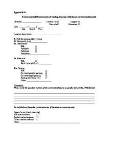
Block Diagram – STP-DRV-xxxx STP-DRVA-RC-050 & STP-DRVA-BR-100 xx VDC + Power – Supply (match power supply V to drive)
Vin+ VinVout-
Regen Clamp STP-DRVA -RC-050
Vout+ Resistor (optional) STP-DRVA-BR-100 10Ω 100W STP-DRV-xxxx Drive #2 (optional)
R1 R2
V+
V+
V–
V–
STP-DRV -xxxx Drive #1
(optional 100W resistor also available) • �Mounted on a heat sink • �Voltage range: 24–80 VDC; no user adjustments required • �Power: 50W continuous; 800W peak • �Wire connection: 6-pin screw terminal block; 12–18 AWG wire • �Indicators (LED): Green = power supply voltage is present Red = clamp is operating (usually when stepper is decelerating) • �Protection: The external power supply is internally connected to an “Input Diode” in the regen clamp that protects the power supply from high regeneration voltages. This diode protects the system from connecting the power supply in reverse. If the clamp circuit fails, the diode will continue to protect the power supply from over-voltage. • �RoHS
SureStep™ Stepping Systems – Braking Accessories Part Number
Description
STP-DRVA-RC-050* Regeneration Clamp: use with DC-powered stepper & servo drives; 50W, 24–80 VDC STP-DRVA-BR-100
Braking Resistor: use with STP-DRV-RC-050 regen clamp; 100W, 10 ohms
* Do not use the regeneration clamp in an atmosphere containing corrosive gases.
A–2
SureStep™ Stepping Systems User Manual
5th Ed., Rev. A
10/2018
Appendix A: SureStep™ Accessories
Dimensions – STP-DRVA-RC-050 Dimensions = in [mm] 2.50 [63.5]
4.00 [101.6]
4X Ø0.12 [Ø3.0]
3.75 [95.3]
3.00 [76.2] 0.24 [6.1]
0.16 [4.0]
3.69 [93.7] 4-40 UNC
3X Ø0.12 [Ø3.0]
2.21 [56.2]
1.50 [38.1]
1.25 [31.8]
1.17 [29.7] 1.24 [31.5]
1.20 [30.6]
0.87 [22.1]
Dimensions – STP-DRVA-BR-100 Dimensions = in [mm] 5.87 [149.1] 5.46 [138.7]
2X R0.16 [R4.0] 1.50 [38.1]
0.75 [19.1] 22.00 [558.8]
0.13 [3.3] 0.75 [19.0]
STP-DRVA-RC-050 STP-DRVA-BR-100
5th Ed., Rev. A
010/2018
SureStep™ Stepping Systems User Manual
A–3
Appendix A: SureStep™ Accessories
Cables and Accessories Replacement cables and connector kits are available for use with SureStep motors, drives, and integrated motors/drives. See the table below for available accessories and the parts they are compatible with.
SureStep Cables & Accessories Part Number
Description
Use With All STP-MTRD except STPMTRD-17038 and 17038E STP-DRV-4850 STP-DRV-80100
STP-CON-1
SureStep replacement connector kit.
STP-CON-2
SureStep replacement connector kit.
STP-CON-3
SureStep replacement connector kit.
STP-485DB9-CBL-2
Integrated motor/drive programming cable
STP-MTRD-xxxxxR
STP-USB485-4W
USB to RS-485 adapter, 4-wire
STP-MTRD-xxxxxR
STP-EXT-0xx
Motor to drive extension cable, xx = length in feet Motor to drive extension cable, xx = length in feet Motor to drive extension cable, xx = length in feet Control cable for 17038 series integrated motor/ drives, xx = length in feet
STP-EXTL-0xx STP-EXTH-0xx STP-CBL-CAxx STP-CBL-EAxx
Encoder cable, xx = length in feet
STP-CBL-EBxx
Encoder cable, xx = length in feet
STP-CBL-EDxx
Encoder cable, xx = length in feet
STP-MTRA-17DMP
Metal body SureStep damper. For use with NEMA 17 stepper motors with 5mm shafts. Metal body SureStep damper. For use with NEMA 23 stepper motors with 1/4 in. shafts.
STP-MTRA-23DMP STP-USBENC-CBL-1
A–4
USB configuration cable
SureStep™ Stepping Systems User Manual
STP-DRV-6575
STP-MTR-xxxxx(x) STP-MTRL-xxxxx(x) STP-MTRH-xxxxx(x) STP-MTRD-17038/17038E STP-MTRD-xxxxxE STP-MTRA-ENC1 STP-MTRA-ENC3 STP-MTRA-ENC5 STP-MTRA-ENC7 STP-MTRA-ENC9 STP-MTRA-ENC10 STP-MTRA-ENC2 STP-MTRA-ENC4 STP-MTRA-ENC6 STP-MTRA-ENC8 STP-MTR-17xxx(x) STP-MTR-23xxx(x) STP-MTRA-ENCx
5th Ed., Rev. A
10/2018
Appendix A: SureStep™ Accessories STP-EXTx-0xx Extension Cable Wiring Diagram
24AWG = EXTL cables 20AWG = EXT cables 18AWG = EXTH cables
STP-USBENC-CBL-1 Wiring Diagram
STP-485DB9-CBL-2 Wiring Diagram
5th Ed., Rev. A
010/2018
SureStep™ Stepping Systems User Manual
A–5
Appendix A: SureStep™ Accessories STP-CBL-EAxx Encoder Cable Wiring Diagram
STP-CBL-EDxx Encoder Cable Wiring Diagram
A–6
SureStep™ Stepping Systems User Manual
5th Ed., Rev. A
10/2018
Appendix A: SureStep™ Accessories STP-CBL-EBxx Encoder Cable Wiring Diagram NOTE: 1. Case_GND is connected internally to GND (BLACK/RED) 2. Ground connected internally to cable shielding-customer ref. only 3. Tolerance: ± 0.2” [5] unless otherwise specified 4. All meterials must be ROHS compliant
CABLE NUMBER STP-CBL-EB3 STP-CBL-EB6 STP-CBL-EB10 STP-CBL-EB20
TABLE INFORMATION CABLE LENGTH L 3 Feet 6 Feet 10 Feet 20 Feet
L ±0.5 1.50 ±0.05 [38.100 ±1.270]
2
A
3
6.0 [152.400]
0.25±0.05 [6.350±1.270]
round dual shielding jacket
1
Leads Stripped and Tinned Case_GND
heat shrink tube with glue 2X (1 [25])
A
Note 1
Special Label PANDUIT # LJSL5-Y3-2.5
3.0 [76.20]
#8 Insulated Terminal Ring or Equivalent
Ground
AUTOMATION DIRECT STP-CBL-EBxx
0.5 [13]
3.0 [76.20] #8 Insulated Terminal Ring or Equivalent
# 4 6 8 9
10 11 12 13
Connector Pinout Color Function Primary Stripe GND Red Black Black +5V Red Green Black B+ Green Black BBlack White A+ White Black ABlue Black Z+ Black Blue Z-
17 15 13 11 9 7 5
Note 2
3 1
16 14 12 10 8 6 4 2 SECTION A-A SCALE 3:1 (Back of Connector Housing)
# 1 2 3
PART CABLE CONNECTOR CRIMP PINS
PARTS LIST QTY DESCRIPTION 1 3M # 3600B/14 1 JAE # FI-W175 8 JAE #FI-C3-A1-15000
STP-CBL-CAxx Control Cable Wiring Diagram *
* Refer to STP-CBL-CAxx part number for cable length information
Note: For Rev A of this cable, STEP+ is Grey/Pink and EN- is Red/Blue
5th Ed., Rev. A
010/2018
SureStep™ Stepping Systems User Manual
A–7
Appendix A: SureStep™ Accessories
Encoder Options The standard integrated motors and dual-shaft stepper motors have options for mounting an external encoder. The NEMA 14, 17, and 23 dual-shaft motors come with pre-tapped holes on the rear end cap for mounting the STP-MTRAENCx encoders. The “E” stepper motors and integrated models come with an encoder installed. This encoder can be replaced with other options. All STPMTRA-ENCx encoders are incremental A/B quadrature type. Please see the compatibility table below. NOTE: Using the CLICK or BRX PLC requires the use of an FC-ISO-C signal conditioner.
Encoder Compatibility Encoder Part Number
PPR
STP-MTRA-ENC1
1000
STP-MTRA-ENC2
1000
STP-MTRA-ENC3
400
STP-MTRA-ENC4
400
STP-MTRA-ENC5
1000
STP-MTRA-ENC6
1000
STP-MTRA-ENC7
400
STP-MTRA-ENC8
400
PLC Bore Output Type Compatibility Diameter
STP-MTRx-14xxxD STP-MTRx-14xxxE STP-MTRx-17xxxD P2-HSI, P3-HSI, STP-MTRx-17xxxE Line Driver BRX2, CLICK Standard STP-MTRDC0-1xDxE-D2 xxxxxE BRX3, CLICK Push-pull (totem) C0-1xDxE-D3 P2-HSI, P3-HSI, BRX2, CLICK C0-1xDxE-D2 BRX3, CLICK Push-pull (totem) C0-1xDxE-D3 Line Driver
0.25 inch
STP-MTRA-ENC10
P2-HSI, P3-HSI, BRX2, CLICK C0-1xDxE-D2 BRX3, CLICK Push-pull (totem) C0-1xDxE-D3 Line Driver
5mm
STP-MTRA-ENC9
Motor Compatiblity
48 to 4096 Configurable1 2mm - 8mm (default = 400)
P2-HSI, P3-HSI, BRX2, CLICK C0-1xDxE-D2 BRX3, CLICK Push-pull (totem) C0-1xDxE-D3 Line Driver
Line Driver
P2-HSI, P3-HSI, BRX2, CLICK C0-1xDxE-D2
Push-pull (totem)
BRX3, CLICK C0-1xDxE-D3
STP-MTRx-23xxxD STP-MTRx-23xxxE
STP-MTRx-14xxxD STP-MTRx-14xxxE STP-MTRx-17xxxD STP-MTRx-17xxxE STP-MTRx-23xxxD STP-MTRx-23xxxE Standard STP-MTRDxxxxxE
1 - Requires configuration cable STP-USBENC-CBL-1 2 - Requires FC-ISO-C with DIP configuration 1 (see below) 3 - Requires FC-ISO-C with DIP configuration 2 (see below)
A–8
SureStep™ Stepping Systems User Manual
5th Ed., Rev. A
10/2018
Appendix A: SureStep™ Accessories
FS-ISCO-C DIP Configuration 1
FS-ISO-C DIP Configuration 2
Input DIP
1
2
3
4
5
6 7 8
Input DIP
1
2
3
4
5
Setup
1
1
1
0
0
0
Setup
1
1
1
0
0
1
Output DIP
1
2
3
4
5
6 7 8
Output DIP
1
2
3
4
5
6 7 8
Setup
0
0
0
0
0
0
Setup
0
0
0
0
0
0
0 0
0 0
6 7 8 1 0
1 0
Required Encoder Mounting Screws Step Motor
Qty Screw Description Part Number
STP-MTRx-14xxx(D) or (E)
2
STP-MTRx-17xxx(D) or (E)
2
STP-MTR-17060(D) or (E)
3
STP-MTRx-23xxx(D) or (E)
2
STP-MTRD-xxxxx(E)
2
5th Ed., Rev. A
010/2018
M2.5 X 0.45 mm, 5mm long, 8-18 SS Button Head Hex Drive Screw
Image
McMaster Carr PN#: 92095A457
M2 X 0.4 mm, 5mm McMaster Carr long 18-8 SS Pan PN#: 92000A012 Head Phillips Screws 4-40, 0.25 in long, 18-8 SS Pan Head Phillips Screw with captive washer
Olander.com PN#: 4C25PPIS
M3 X 0.5 mm, 8mm McMaster Carr long 18-8 SS Pan PN#: 94102A103 Head Phillips Screws
SureStep™ Stepping Systems User Manual
A–9
Appendix A: SureStep™ Accessories
Encoder Specifications Encoder General Specifications Encoder Operating Temperature, CPR < 2000 Operating Temperature, CPR ≥ 2000 Vibration Electrostatic Discharge Max. Shaft Axial Play Max Shaft Eccentricity plus Radial Play Max Accleration Typical Product Weight Hub Set Screw Hex Wrench Size Phase Relationship
A–10
STP-MTRA-ENC1, STP-MTRA-ENC2, STP-MTRA- STP-MTRA3, 5, 7 4, 6, 8 ENC9 ENC10 -40 to 100°C (-40 to 212°F) -40 to 125°C (-40 to 257°F) -25 to 100°C (-13 to 212°F) 20G (5Hz to 20kHz) ±2kV
±4kV
±0.010 inches [0.254 mm]
5G (10Hz-500Hz) n/a
n/a
± 0.012 inches [0.3 mm]
0.004 inches
n/a
n/a
250000 rad/sec2
n/a
n/a
0.91 oz. [25.8 g]
0.82 oz [23.2 g] #4-48
0.050 inches A leads B for clockwise shaft rotation, and B leads A for counterclockwise rotation as viewed from the cover side of the encoder.
SureStep™ Stepping Systems User Manual
0.55 oz [15.7 g] n/a
n/a
n/a
n/a
A leads B for counterclockwise shaft rotation, and B leads A for clockwise rotation as viewed from the cover side of the encoder.
5th Ed., Rev. A
10/2018
Appendix A: SureStep™ Accessories
Differential Electrical Specifications The following specifications apply over the entire operating temperature range. Typical values are specified at Vcc = 5.0VDC and 25°C.
Encoder Electrical Specifications STP-MTRASTP-MTRAENC1, 3, 5, 7 ENC2, 4, 6, 8
Encoder Supply Voltage (V)
Min.
4.5
Typical
5
Max Supply Current (mA)1 Low-level Output2 (V) High-level Output3 (V)
STP-MTRAENC9
STP-MTRAENC10
5.5
Typical
29 (CPR < 500) 56 (CPR ≥ 500)
27 (CPR < 500) 54 (CPR ≥ 500)
Max
36 (CPR < 500) 65 (CPR ≥ 500)
33 (CPR < 500) 62 (CPR ≥ 500)
n/a
n/a
Typical
0.2
n/a
n/a
n/a
Max
0.4
0.5
0.1
0.1
Min
2.4
2.0
3
VDD-0.1
Typical
3.4
n/a
n/a
n/a
15
110/100
11
8
Rise/Fall Time (nS)
16
1: No load 2: IOL (Amps at Output Low) = 20mA max. (for -ENC1 through -ENC8) 3: IOH (Amps at Output High) = 20mA max. (for -ENC1 through -ENC8)
5th Ed., Rev. A
010/2018
SureStep™ Stepping Systems User Manual
A–11
Appendix A: SureStep™ Accessories
Wiring Examples Please see the pages below for wiring examples:
For STP-MTRA-ENC1, -ENC3, -ENC5, -ENC7 STP-MTRA-ENC1
STP-CBL-EAx Pin
+5V GND
D
D
D
7 2
A+
6
BLU
5
A+
A−
BLU/WHT
A−
B+
10
BRN
9
B+
B−
BRN/WHT
B−
Z+
4
ORG
3
Z+
Z−
ORG/WHT
Z−
Optical Encoder Line Driver Wiring Diagram
For STP-MTRA-ENC2, -ENC4, -ENC6, -ENC8 STP-MTRA-ENC2, 4, 6, 8 Pin
+5V GND A
STP-CBL-EBx
RED
4 1
BLACK
3
WHITE
5
BROWN
A− A+
B
B+
Z (Index)
Z+
B− Z−
Optical Encoder Totem Pole Wiring Diagram
A–12
SureStep™ Stepping Systems User Manual
5th Ed., Rev. A
10/2018
Appendix A: SureStep™ Accessories For STP-MTRA-ENC9 STP-MTRA-ENC9
STP-CBL-EBx Pin
6
+5V
4
BLK/RED
A+
10
WHT/BLK
11
A+
A−
BLK/WHT
A−
B+
8
GRN/BLK
9
B+
B−
BLK/GRN
B−
Z+
12
BLU/BLACK
13
Z+
Z−
BLACK/BLU
Z−
GND
D
D
D
RED/BLK
Configurable Encoder Line Driver Wiring Diagram
For STP-MTRA-ENC10 STP-MTRA-ENC10 Pin
+5V GND
STP-CBL-EBx
RED/BLK
6 4
BLK/RED
A+
10
WHT/BLK
N/A
11
BLK/WHT
B+
8
GRN/BLK
N/A
9
BLK/GRN
Z+
12
BLU/BLACK
N/A
13
BLACK/BLU
A+
B+
Z+
Configurable Encoder Totem Pole Wiring Diagram
5th Ed., Rev. A
010/2018
SureStep™ Stepping Systems User Manual
A–13
Appendix A: SureStep™ Accessories Productivity PLCs
P2-HSI or P3-HSI
A+ A− B+ B− Z+ Z−
1A 169Ω SureStep Advanced Stepper Drives
1A 1B
169Ω
A+
Internal to the STP-DRV-xxxx
220pF
1B 1Z
330Ω
A− 169Ω
330Ω
B+
220pF
1Z
B−
Productivity PLC Wiring Diagram
SureStep Advanced Stepper Drive Wiring Diagram
SureServo SVA-2xxx
Terminal Block & Cable ZL-RTB50 & ZL-SVC-CBL50
Servo Drive 24VDC Max. input pulse frequence is 500kpps
A+
/SIGN 5V
A−
270Ω
SIGN COM−
B+
/PULSE 5V
B−
270Ω
PULSE COM− VDD GND
SureServo Wiring Diagram
A–14
SureStep™ Stepping Systems User Manual
5th Ed., Rev. A
10/2018
Appendix A: SureStep™ Accessories
BRX High Speed Inputs Line Driver (Differential)
BRX MPU Input
A+ FC-ISO-C
A−
nC 0
+Ai
1
2
3
4
-Ai
B+
+Bi
B−
+Zi
Z+
COM
-Bi
Open Collector (single ended)
-Zi COM
Z−
V+
12-24 VDC
0V Ao Ao
ISOLATION BOUNDARY
Bo Bo Zo Zo 0V 0V
FC-ISO-C BRX PLC Wiring Diagram
CLICK High Speed Inputs Line Driver (Differential) A+ A−
FC-ISO-C +Ai -Ai
B+
+Bi
B−
+Zi
Z+
COM
Z−
-Bi -Zi
C1
COM V+ 0V
12-24 VDC
Ao
ISOLATION BOUNDARY
Ao Bo Bo Zo Zo
X1 X2 X3
0V 0V
FC-ISO-C CLICK PLC Wiring Diagram
5th Ed., Rev. A
010/2018
SureStep™ Stepping Systems User Manual
A–15
Appendix A: SureStep™ Accessories
BLANK PAGE
A–16
SureStep™ Stepping Systems User Manual
5th Ed., Rev. A
10/2018