simple and easily diagnosable tests. AN012146-1. FIGURE 1. Demonstration
System Layout. Fairchild Semiconductor. Application Note 1037. February 1996.
Is Now Part of
To learn more about ON Semiconductor, please visit our website at www.onsemi.com
ON Semiconductor and the ON Semiconductor logo are trademarks of Semiconductor Components Industries, LLC dba ON Semiconductor or its subsidiaries in the United States and/or other countries. ON Semiconductor owns the rights to a number of patents, trademarks, copyrights, trade secrets, and other intellectual property. A listing of ON Semiconductor’s product/patent coverage may be accessed at www.onsemi.com/site/pdf/Patent-Marking.pdf. ON Semiconductor reserves the right to make changes without further notice to any products herein. ON Semiconductor makes no warranty, representation or guarantee regarding the suitability of its products for any particular purpose, nor does ON Semiconductor assume any liability arising out of the application or use of any product or circuit, and specifically disclaims any and all liability, including without limitation special, consequential or incidental damages. Buyer is responsible for its products and applications using ON Semiconductor products, including compliance with all laws, regulations and safety requirements or standards, regardless of any support or applications information provided by ON Semiconductor. “Typical” parameters which may be provided in ON Semiconductor data sheets and/or specifications can and do vary in different applications and actual performance may vary over time. All operating parameters, including “Typicals” must be validated for each customer application by customer’s technical experts. ON Semiconductor does not convey any license under its patent rights nor the rights of others. ON Semiconductor products are not designed, intended, or authorized for use as a critical component in life support systems or any FDA Class 3 medical devices or medical devices with a same or similar classification in a foreign jurisdiction or any devices intended for implantation in the human body. Should Buyer purchase or use ON Semiconductor products for any such unintended or unauthorized application, Buyer shall indemnify and hold ON Semiconductor and its officers, employees, subsidiaries, affiliates, and distributors harmless against all claims, costs, damages, and expenses, and reasonable attorney fees arising out of, directly or indirectly, any claim of personal injury or death associated with such unintended or unauthorized use, even if such claim alleges that ON Semiconductor was negligent regarding the design or manufacture of the part. ON Semiconductor is an Equal Opportunity/Affirmative Action Employer. This literature is subject to all applicable copyright laws and is not for resale in any manner.
Fairchild Semiconductor Application Note 1037 February 1996
This application example discusses the implementation of embedded, system level boundary scan test within an actual design, the Fairchild boundary scan demonstration system. Its intent is to describe the decisions, actions and results when applying boundary scan and Fairchild’s SCAN EASE Software within a system. For more information see also AN-1022, “Boundary Scan Silicon and Software Enable System Level Embedded Test.”
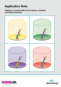
Functionally, the system is designed to display messages and system status information using the LCD display located on each I/O card. This message and status information is driven from the processor card, via the system backplane, or from EPROMs local to each I/O card. To demonstrate the features and functions of boundary scan, the system also contains LEDs which display the status of boundary scan activity.
HARDWARE DESCRIPTION The Fairchild boundary scan demonstration system is comprised of a multidrop backplane which interconnects a processor card to several system I/O cards. The backplane contains a 16-bit data bus, a 16-bit address bus and several control signals routed to six connectors. The processor card consists of a processor core which includes a Motorola 68302 µP, boot EPROM and working SRAM, a RS232 port for remote communication, a parallel backplane interface and an auxiliary parallel port. The I/O cards, each sharing an identical architecture, include a 16-bit LCD display, an on board EPROM which stores LCD messages, and a backplane interface. Each I/O card also contains logic which multiplexes data, from either the backplane or EPROM, to the display. The number of I/O cards can vary within a given system. While five backplane I/O card connectors are available, only 2 of the 5 slots are typically populated with I/O cards. The multidrop (i.e. parallel) backplane architecture enables cards to populate any of the five connectors and allows connectors to remain empty. Board addressing is used to select cards for functional operation.
TEST OBJECTIVES The fundamental test objective for the Fairchild demonstration system was to utilize techniques which could be applied over the life of the product, including development, manufacturing and in-field operation. With effective prototyping to ensure functionality and timing performance, printed circuit board (PCB) structural faults, resulting from manufacturing errors or in-system board stress (e.g., temperature changes or mechanical stresses), were the primary focus. Boundary scan was seen as an effective means of detecting and diagnosing printed circuit board failures at all stages of the product’s life cycle. A specific area of concern during the development of the test strategy was system level test. Typically, limited tester access forces system test to rely on functional patterns to test for even simple interconnect failures. This leads to very complex test patterns, poor fault coverage and very difficult failure diagnostics. More importantly, the functional test routines depend on sound interconnects between components to be effective. Embedded, system-level boundary scan was perceived as a way to replace many of the functional tests with simple and easily diagnosable tests.
© 1998 Fairchild Semiconductor Corporation
AN012146
www.fairchildsemi.com
AN-1037
AN012146-1
FIGURE 1. Demonstration System Layout
Embedded IEEE 1149.1 Test Application Example
Embedded IEEE 1149.1 Test Application Example
AN012146-2
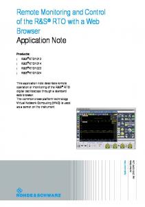
FIGURE 2. Demonstration Processor Card To increase the structural fault coverage on nets connected to devices which are not available with boundary scan, a “cluster test” can be implemented. A cluster test relies on at least two boundary scan components and a functional knowledge of the cluster (i.e., cluster of devices) connected between them. Using one 1149.1 compliant component to drive test vectors to the cluster and the other to receive expected data from the cluster, the structural integrity of the cluster can be evaluated. As the number and complexity of components increases, the development of test vectors becomes more difficult and diagnostic resolution increases. Within the demo system, a cluster test was implemented on the processor card’s auxiliary port (see Figure 2 ).
Boundary scan was viewed as only a part of the complete test solution. Functional test routines were still required to test system memory and confirm effective µP-to-system peripheral communication. Using the two techniques together maximized test effectiveness while reducing test development efforts. IEEE 1149.1 COMPLIANT SYSTEM ARCHITECTURE To accomplish the boundary scan test objectives, the 1149.1 test strategy covered three aspects of the system: board and backplane boundary scan test points, system level boundary scan access and embedded boundary scan control. Board and Backplane Test Points The first step in implementing boundary scan is to integrate 1149.1 compliant components into the functional design. Maximizing the percentage of nets covered by boundary scan reduces the cost of other techniques and equipment like in-circuit testers, while increasing the ability to apply the benefits of boundary scan at later phases of the product’s life cycle. In the case of the Fairchild demo system, boundary scan was included on nearly every logic IC which populated the processor card and I/O cards. To support backplane interconnect testing, Fairchild’s 18-bit SCAN ABT Test Access Logic components were implemented at the backplane interface on both the processor card and I/O cards. Using 1149.1 compliant SCAN ABT logic (SCAN182245A) provided the required backplane test points while also creating a hot insertable (Note 1) backplane interface. The hot insertable interface allowed failing processor or I/O cards to be removed or inserted without powering down the system.
www.fairchildsemi.com
On future demo design revisions, boundary scan will be expanded beyond the logic components to include an 1149.1 compliant microprocessor and programmable device (i.e., integrating the separate, non-1149.1 programmable devices into a single 1149.1 FPGA or CPLD). These additions will continue to drive the structural fault coverage towards 100% and also provide non-test capabilities, such as µP emulation and in-system FPGA programming via the JTAG port. Note 1: Fairchild’s SCAN ABT 18-bit boundary scan like SCAN182245A devices provide level II hot insertion. Level II insertion insures that the components can be inserted into a powered on system without component damage. See the SCAN182245A datasheet for more information on power-up reset and definition of Level 1, 2, 3 live insertion.
System Level Boundary Scan Access and Partitioning With the 1149.1 components placed on the processor and I/O cards, the next objective is to interconnect the 1149.1 component TAP signals—TMS, TCK, TDI, TDO and
2
SCANPSC110F bridge, component at the backplane interface of the processor card and each I/O card. The SCANPSC110F bridge provides two key features to efficiently interconnect and partition a 1149.1 compliant system:
TRST—at both the board and system levels. For the Fairchild demo design, this task was accomplished by adding a 5-bit bus to the backplane design and placing a Fairchild Hierarchical and Multidrop Addressable JTAG Port,
AN012146-3
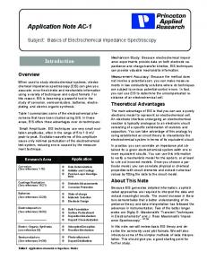
FIGURE 3. Demonstration I/O Card
• System Level Partitioning: The SCANPSC110F bridge provides an addressable, multidrop interface to a single backplane TAP bus. This multidrop TAP interface is a perfect fit for this application because it preserves the ability for cards to be placed in any of the backplane connectors and for connectors to be left empty without requiring an entirely new set of boundary scan test vectors. Using a 1149.1 protocol, each SCANPSC110F bridge and, in turn, each board, can be addressed to participate in boundary scan test operations. • Board Level Partitioning: Typically, board level boundary scan components are connected to form a single chain. The SCANPSC110F bridge provides three local scan ports (LSPs) which allows board level components to be partitioned into smaller, more manageable chains. Using the SCANPSC110F bridge’s internal data registers, the LSPs can be configured to individually connect a single scan chain to the backplane TAP or to simultaneously connect up to three scan chains in series with the backplane TAP. The ability to partition a board and system using the SCANPSC110F bridge simplifies test development, im-
proves test efficiency and allows failures to be diagnosed to the partition level without using an off-line diagnostics tool. However, these benefits are only realized if the 1149.1 components are intelligently grouped and connected. The objective for testing the demo system was to test each board as a separate entity and to test the interconnects between the boards (i.e., the backplane). Enabling each board to be tested separately was easily accomplished when the SCANPSC110F bridge was placed at each card’s backplane interface and connected to a system wide backplane TAP. With this interface, the tester TAP signals could be applied to each board separately. With exclusive access to each board, the next critical task was to select which board components were grouped and connected to the SCANPSC110F bridge LSPs. Again, the test objectives were considered. To enable the development of an efficient, backplane specific boundary scan test, the 1149.1 compliant backplane interface components on each card were exclusively assigned to a single LSP. To group and assign the remaining 1149.1 compliant, board-level components to the other two SCANPSC110F bridge LSPs, each board type was viewed separately. 3
www.fairchildsemi.com
AN012146-4
FIGURE 4. Backplane—Hierarchical Connection Embedded Boundary Scan Test Control The final step of a boundary scan hardware design is to provide the means to apply and evaluate the boundary scan test vectors. For boards and systems which are tested using an external tester, the hardware implementation simply involves adding an applicable tester interface; e.g., additional pins on the edge connector, a special purpose connector/header or vias for ICT probes. For boards and systems which don’t permit physical access, and/or require self-test or remote test capability, the test control must be embedded within the system. For designs which require embedded test control, the optimal hardware implementation is one which enables both embedded and external tester access. This allows the design to benefit from the strengths of each method. The external tester offers the best means of developing tests for hardware debug and manufacturing. Using the ATPG and diagnostic tools provided with the external tester, tests can be easily developed and modified. Once the tests have been applied, failures can be diagnosed to the net or pin level automatically. With the tests finalized, and the boards/system tested, the tests and control are embedded to provide self-test and remote test access capability. The Fairchild demo system hardware was designed to support both embedded and external test application. With the ability to address each demo card separately using the SCANPSC110F bridge, embedded and external access was
For the processor cards, the remaining compliant components were grouped an an internal logic chain and an auxiliary port logic chain. As with the backplane partition, these groups were selected to enable the development of group specific tests. The auxiliary port is intended to support a connection to a 1149.1 compliant sub-system. Assigning the port’s compliant components to a unique LSP allows tests to be generated specifically for this port (and what is connected to it). The internal logic covers all other board level 1149.1 compliant components. A similar component group was implemented for each I/O card. The internal card logic was grouped and assigned to one LSP while the other LSP was connected directly back to the backplane connector in order to provide a hierarchical connection. A hierarchical bridge connection is realized by connecting one SCANPSC110F bridge’s LSP to a second SCANPSC110F bridge’s backplane interface TAP. Hierarchical connections enable board scan chains to be split into more than the three chains supported by a single bridge. Hierarchical connections also enable a system to be partitioned into addressable sub-systems. In the case of the demonstration design, the hierarchical configuration was implemented to show the concept and addressing scheme required to address a bridge and its LSPs hierarchically. Since each I/O card shares an identical architecture, each I/O card’s LSP3 connects directly to the backplane edge connector. The hierarchical connection is then realized using backplane routing between Con 5 and Con 6 (see Figure 4 ).
www.fairchildsemi.com
4
The SCAN EASE source code can be conditionally compiled to run directly on a 1149.1/100F PC-AT card. With a connection to the demo processor card’s TAP connector, SCAN EASE was developed and debugged using a commerically available ANSI C debugger.
only required on the processor card. The processor card then acted as the master to test each card and the backplane.
• Embedded Test: The embedded test capability for the demo system was implemented using the processor card’s µP and the Fairchild SCANPSC100F Embedded Boundary Scan Controller. The SCANPSC100F provides an efficient, asynchronous interface between the µP’s parallel data bus and the serial 1149.1 TAP, and is fully supported by the SCAN EASE software tools. The generic, asynchronous interface allows SCANPSC100F to interface with a wide range of processors and operate independent of the processor’s operating frequency. The microprocessor views the SCANPSC100F as a standard I/O device. The processor card provided two options to initiate and evaluate embedded tests. For a power-on or post-reset self test, an LED display block was included with a separate LED for each card in the system. To initiate/evaluate tests remotely, the UART on the microprocessor was configured to provide an RS232 interface and an RS232 connector was added to the processor card. This remote interface also allows new tests to be downloaded and results to be uploaded. • External Test: To provide system level access to an external tester, a connector was added to the processor card. In addition to the required tester signals, this connector included a sense line tied to the output enable pin on the SCANPSC100F. When the external tester was connected, the sense line was pulled high disabling the TAP pins on the SCANPSC100F. This, in turn, disabled the embedded tester and allowed the external tester, alone, to control the system TAP. Figure 2 shows the high level connection between the µP, SCANPSC100F and external connector.
ATPG (Automatic Test Pattern Generation) Software Tool Both the PM3705 and 1149.1/100F PC-AT card are supported by the JTAG Technologies ATPG tool, called VIP (Vector Interface Package). This tool automatically generates system level 1149.1 structural tests using four user-provided input files:
• BSDL Selection File: Boundary Scan Description Language files, which are provided by the component vendor or ASIC designer, define the specific implementation of 1149.1 features with an IC (see Fairchild SCAN Databook Section 6 Boundary Scan Design Support). With VIP, the user must create a BSDL selection file which provides the directory path to the BSDL file for each 1149.1 component included in a given test. • PCB Net List (in BNET Format): A net list is automatically created by the PCB design and layout tool used to develop the PCB. The user must convert this net list format to a specific format which is read by VIP. This VIP format, called BNET, contains only the boundary scan nets. It also defines the connection of 1149.1 components in each boundary scan chain and associates a tester TAP with each chain. • Connection File: This file defines the connection between each tester TAP (provided in the BNET file) and the SCANPSC110F bridges LSPs. It also defines how the SCANPSC110F bridges are connected to the backplane TAP and to each other (e.g., multidrop or hierarchical). • Pin Constraint File: This file defines I/O pins in the net list which are pulled to fixed logic levels, I/O pins which must remain in the high-impedance state during a test to avoid bus contention, or system inputs which must maintain a specific logic level during a boundary scan test (e.g., a reset input pin).
IEEE 1149.1 TEST EQUIPMENT Hardware A wide range of 1149.1 compliant testers are commercially available, ranging from in-circuit testers to PC-AT cards. For the demo system, the requirements for the tester hardware were low cost and portability. Based on these factors, two testers were selected: the JTAG Technologies PM3705 and the Corelis 1149.1/100F PC-AT card. The PM3705 is a portable controller box which connects to a PC’s parallel I/O port. It provides two 1149.1 TAPs and connects to the demo system via a 10-pin connector. Connectors are placed on each board (per PSC110F bridge LSP) to support board level test and on the processor card to support processor card and system level test. The PM3705 was used primarily for low volume board and system level manufacturing test, and for externally driven in-field test using a laptop computer. The Corelis 1149.1/100F PC-AT card is based on Fairchild’s SCANPSC100F which provides the ideal development platform for developing and debugging SCAN EASE functions.
SCAN EASE Software Tools All three of the tools within SCAN EASE were utilized to develop and test the demonstration system:
• EmbedPrep: This tool was used to translate test vectors from the JTAG Technologies pattern format (PAT) to Embedded Vector Format (EVF). EVF is a compacted, ATPG-independent format that is used by the other SCAN EASE tools. EmbedPrep has no dependence on system hardware and is discussed further in the Embedding the Test Vectors section.
5
www.fairchildsemi.com
•
prior to embedding the code within the system, minimized the time required to program a new EPROM each time a change to the code was made.
EmbedCom: The EmbedCom tool is a Windows-based GUI which provides a user-friendly interface to the embedded test system. With this GUI, system self-test is initiated, new tests are downloaded to system RAM, pass fail information is displayed and datalogs can be uploaded. The GUI allows a user to test the system with no knowledge of 1149.1 or the embedded test code.
The final aspect of EmbedTest is the serial communication code. EmbedTest includes two modules which support serial communication. The highest level module interprets the commands entered using the EmbedCom GUI or generic emulator, and calls the appropriate EmbedTest application functions. The other, lower level, module is a UART specific device driver. For the demo, this device driver was specific to the Motorola 68K RS232 UART. The device driver configures and controls the UART hardware.
•
EmbedTest: This tool, provided as ANSI C source code, contains functions which communicate with the system hardware and manage the application/evaluation of test data. Three aspects of the code must be considered when integrating EmbedTest into a specific design: integrating the EmbedTest functions with the application’s operating system and system application code; mapping the SCANPSC100F addresses within the system; and implementing the drivers to support the µP specific UART (if serial communication with the EmbedTest code is required). EmbedTest was written as multi-level modules. These levels range from the SCANPSC100F device drivers to a module called PG__CTRL which oversees the execution of tests and initialization of the test hardware. Integration with the system’s operating system and application code is performed at the program control level. For the demo system, no operating system was implemented. A simple boot up routine was implemented to initialize the processor card hardware and run EmbedTest. A self-test was run immediately after power up (or after a manual system reset button was pressed), then the system polled the RS232 port for further instruction.
TEST DEVELOPMENT Developing Test Vectors In a previous section, the concept and benefit of system/ board test partitioning was discussed. With the partitions defined in hardware, the next step is to develop tests corresponding to each partition. For the Fairchild demo application, separate tests were developed using the JTAG ATPG tool for each card and for the backplane. When applying embedded tests using SCAN EASE, each test is applied and evaluated separately. This enables SCAN EASE to provide pass/fail results for each test. For the demo, this level of resolution was enough to allow boards to be replaced and then fully diagnosed later using an external tester.
•
EmbedTest includes three device driver options for mapping the SCANPSC100F. Two of the three drivers, the PSC100F in a memory mapped architecture and the PSC100 in an I/O mapped architecture, were included to ensure that the SCANPSC100F could be implemented with any commercially available microprocessor. For the demo, a Motorola 68K µP was used and, therefore, the memory mapped driver was selected. EmbedTest uses a conditionally defined macro to allow the user to easily specify the driver option. The third SCANPSC100F driver option was written to support the application of EmbedTest using the SCANPSC100F-based Corelis 1149.1/100F PC-AT card. The demo system was used extensively in the development of the SCAN EASE tools. The Corelis 1149.1/100F PC-AT card enabled the majority of code development to occur on a PC using an ANSI-C debugger. Debugging modifications,
www.fairchildsemi.com
6
I/O Card: Since all I/O cards share identical boundary scan configurations, generating tests to cover every I/O card required only one BNET file, one BSDL selection file and one constraint file. A unique Connection File was then created for each I/O card to provide the SCANPSC110F bridge address and LSP configuration. Samples of these files are shown in Figure 5 through Figure 8. Internal Logic: The internal logic boundary scan test verifies the structural integrity of boundary scan nets within each I/O card. Some nets are shared between the internal logic chain (LSP2) and the backplane interface logic chain (LSP1). To access these shared nets, SCANPSC110F bridge is configured in the connection file to serially connect LSP1 and LSP2. The ATPG then views the LSP1 and LSP2 chains as a single chain and generates tests accordingly.
AN012146-7
FIGURE 6. Sample Connection File
AN012146-5
AN012146-8
FIGURE 7. Sample Constraint File
AN012146-9
FIGURE 8. Sample BSDL Selection File Hierarchical Board Test: (only applies to board populating Con 6): This test verifies the same nets covered in the internal test, but includes an extra SCANPSC110F bridge device in the path between the I/O card and the backplane TAP. The extra SCANPSC110F bridge is handled in the connection file and all other input files are unchanged. The connection file is shown in Figure 9.
AN012146-6
FIGURE 5. Sample BNET File 7
www.fairchildsemi.com
Internal Logic (External Tester): The same process used to generate the internal logic tests for the I/O card was repeated to generate tests for the I/O card’s internal logic nets. A BNET was created to include the boundary scan nets including the local bus nets; the selection file was created to point to the BSDL files; a constraint file was created to force or sense specific values; and a connection file was created, in this case, including all three LSPs in the chain. The processor card’s auxiliary port logic (LSP3) contains a logic component connected between two boundary scan components. Therefore, testing the nets between these devices requires that signals pass through this component. A special list, called a cluster test, was generated to support this connection. To implement a cluster test, the user must provide a set of functional vectors for the cluster logic, in this case a single component. These functional vectors can range from a full functional vector set to only those vectors required to detect interconnect faults. For the JTAG Technologies ATPG tool, VIP, the functional patterns are passed into a post-process file called the APL file. The APL file is later compiled by the VIP tool to generate the test vectors. Internal Logic (Internal Tester): This test is a sub-set of the external tester version. For the embedded test version, boundary scan device outputs which interface the processor local bus were disabled throughout the test. Forcing the boundary
AN012146-10
FIGURE 9. Hierarchical Board Connection File
•
Processor Card: The processor card includes boundary scan nets, but also serves as the test master for the remainder of the system. This dual role dictates that separate internal processor card tests must be created for applications with an external tester versus application with the embedded tester. When applying embedded tests, the 1149.1 components which access and evaluate the processor’s local bus cannot be included in the boundary scan test. Controlling the local bus with boundary scan would prevent the processor from communicating with board resources required to apply the tests. When applying tests with an external tester, the processor communication is not required except with dynamic memory which must be refreshed. Therefore, the local bus boundary scan nets can be tested.
www.fairchildsemi.com
8
scan outputs to a high impedance state was handled in the constraint file. A portion of the constraint file is shown in Figure 10.
AN012146-11
FIGURE 10. Processor Card Internal Logic Constraint File
• Backplane: With tests generated for each board, the only remaining step is to develop tests to evaluate the interconnects between boards. For the JTAG Technologies VIP tool, a backplane test is viewed as just another board test. A BNET file for the boundary scan backplane nets and a connection file are created to indicate the SCANPSC110F bridges and LSPs containing components which interface these nets. In the case of the Fairchild demo, each card’s backplane interface logic was connected to the SCANPSC110F bridges’ LSP1. The backplane test connection file and BNET file are shown in Figure 11 and Figure 12.
9
www.fairchildsemi.com
AN012146-12 AN012146-14
FIGURE 12. Backplane Connection File Embedding the Test Vectors At this point, the hardware design is complete, the tests have been generated and the SCAN EASE code has been integrated into the system. The last step is to embed the test vectors into the system memory. This action requires two phases. First, the vectors must be converted from the ATPG tool’s output file format to EVF. The JTAG Technologies VIP tool generates test patterns in a unique file format, called the pattern format (PAT). To translate the PAT files into EVF files, the SCAN EASE EmbedPrep tool provides a PAT to EVF compiler. The compiler, called PAT2EVF, is an executable file which runs on a PC or workstation. Each PAT file, representing a single test, is entered as an input to the compiler. PAT2EVF also prompts the user for infor-
AN012146-13
FIGURE 11. Backplane BNET File
www.fairchildsemi.com
10
• Embedded Diagnostics: SCAN EASE supports serial communication with the Fairchild demo system. With this link, new tests are downloaded to system RAM. These tests offer tighter diagnostic resolution than the card-level tests which are embedded in system ROM and applied during power on self-test. For example, the power on test simply shows that the card is failing. The downloaded tests may view a specific connection between devices on the card to determine which internal card connections are failing. • Off-line, Pin Level Diagnostics: To provide pin level diagnostics for failing demo cards, an external tester and off-line diagnostics tool was utilized. The connection was made on the processor card to disable the embedded tester and provide access to the entire system. Since the embedded and external testers were connected at the same hardware location and since the embedded/ external tests were identical, the embedded failures were repeatable on the external tester. For a system which does not provide external tester access, an alternative method of running off-line, pin level diagnostics is to use the datalogging option and serial communication capability provided with SCAN EASE to upload failing vectors to a file. This file is the converted to a format that is readable with an off-line tool.
mation regarding the test name, test type and date. The test name, test type and date are included in the EVF’s file header, which is later used by SCAN EASE to associate pass/fail status with the specific test. With each PAT file converted to a corresponding EVF file, the next action required is to actually embed the vectors into memory. For the demo application, an EPROM programmer was used to embed each EVF file into the processor card’s EPROM (the same PROM which contained the SCAN EASE EmbedTest code). EmbedTest uses a single locate statement to point to the embedded EVF vectors. Therefore, the separate EVF files must be appended together before programming the EPROM. EmbedTest uses the file header to determine where each separate EVF file starts and ends within this single, appended EVF file. TEST APPLICATION AND FAILURE DIAGNOSTICS At all stages of the demonstration system’s life cycle, a combination of external and internal tests were performed. For PCB prototyping and board/system manufacturing test, an external test was applied, followed by an embedded test. For field level test, the opposite order was followed. The system was tested using the embedded tester and then, if necessary, tested using the external tester. The order of testing was dependent on the number of failures expected and the ability to diagnose failures with the embedded versus external test methods. During prototyping and manufacturing, each PCB (cards and backplane) is tested for the first time. Therefore, these stages have the highest occurrence of PCB interconnect failures. For the demo application, external testing provided a quick test application and access to the JTAG Technologies diagnostic tool. With this tool, boundary scan failures were diagnosed automatically to the pin and/or net level. This extremely tight resolution facilitated board repairs. Once the failures were resolved, the embedded tests were applied to confirm correct operation of the embedded test routines and to enable execution of the non-boundary scan, functional test routines. During field level test of the demo system, the objective was to quickly confirm that the interconnects were sound and that the system was functioning. Since the system was already thoroughly tested in manufacturing, the likelihood of a failure was very low. For this reason, the embedded self-test was an ideal method of testing the system. For most field applications, the level of field test resolution is at the board or sub-system level. The goal in the field is to minimize system down time. If a failure is found, the board or sub-system is removed, replaced and retested. Depending on the cost, the board or sub-system is discarded or sent back to a repair depot. A similar goal was used for the demo system. With a separate test for each demo card and for the backplane, SCAN EASE was able to provide pass/fail diagnostics to the card/backplane level. If a failure was found, three options were available:
BOUNDARY SCAN BENEFITS REALIZED WITH THE FAIRCHILD DEMO APPLICATION Prototyping Boards and System For the initial hardware debug, boundary scan proved to be a tremendous time saver. It eliminated the structural faults which are often very difficult and time consuming to debug using functional techniques. Once we were sure that the components were effectively placed on each PCB, we were able to focus our efforts on the primary objective of debugging functional and timing related problems. Manufacturing Process Verification Boundary scan provided a means of testing the interconnects for the entire system. With the use of the SCANPSC110F bridge on each card, tests were applied using a single, system wide tester connector, but partitioned for each card and the backplane. Boundary scan enabled efficient failure detection, diagnosis to the pin/net level and PCB repair. Field Level System Test and Diagnostics The Fairchild demonstration system is transported and presented all over the world. Therefore, the ability to test and resolve failures in the field was a key requirement of the test capability. With the ability to embed boundary scan test control within the system, the system interconnects were easily verified prior to each functional presentation. Additionally, remote access to the boundary scan vectors and test application code enabled test downloading and result evaluation to occur using a laptop computer.
• Card Removal: The most simple option was to replace the card with a spare and diagnose the failure at the factory using an external tester.
11
www.fairchildsemi.com
Embedded IEEE 1149.1 Test Application Example LIFE SUPPORT POLICY FAIRCHILD’S PRODUCTS ARE NOT AUTHORIZED FOR USE AS CRITICAL COMPONENTS IN LIFE SUPPORT DEVICES OR SYSTEMS WITHOUT THE EXPRESS WRITTEN APPROVAL OF THE PRESIDENT OF FAIRCHILD SEMICONDUCTOR CORPORATION. As used herein:
AN-1037
1. Life support devices or systems are devices or systems which, (a) are intended for surgical implant into the body, or (b) support or sustain life, and (c) whose failure to perform when properly used in accordance with instructions for use provided in the labeling, can be reasonably expected to result in a significant injury to the user. Fairchild Semiconductor Corporation Americas Customer Response Center Tel: 1-888-522-5372
www.fairchildsemi.com
2. A critical component in any component of a life support device or system whose failure to perform can be reasonably expected to cause the failure of the life support device or system, or to affect its safety or effectiveness.
Fairchild Semiconductor Europe Fax: +49 (0) 1 80-530 85 86 Email:
[email protected] Deutsch Tel: +49 (0) 8 141-35-0 English Tel: +44 (0) 1 793-85-68-56 Italy Tel: +39 (0) 2 57 5631
Fairchild Semiconductor Hong Kong Ltd. 13th Floor, Straight Block, Ocean Centre, 5 Canton Rd. Tsimshatsui, Kowloon Hong Kong Tel: +852 2737-7200 Fax: +852 2314-0061
National Semiconductor Japan Ltd. Tel: 81-3-5620-6175 Fax: 81-3-5620-6179
Fairchild does not assume any responsibility for use of any circuitry described, no circuit patent licenses are implied and Fairchild reserves the right at any time without notice to change said circuitry and specifications.
ON Semiconductor and are trademarks of Semiconductor Components Industries, LLC dba ON Semiconductor or its subsidiaries in the United States and/or other countries. ON Semiconductor owns the rights to a number of patents, trademarks, copyrights, trade secrets, and other intellectual property. A listing of ON Semiconductor’s product/patent coverage may be accessed at www.onsemi.com/site/pdf/Patent−Marking.pdf. ON Semiconductor reserves the right to make changes without further notice to any products herein. ON Semiconductor makes no warranty, representation or guarantee regarding the suitability of its products for any particular purpose, nor does ON Semiconductor assume any liability arising out of the application or use of any product or circuit, and specifically disclaims any and all liability, including without limitation special, consequential or incidental damages. Buyer is responsible for its products and applications using ON Semiconductor products, including compliance with all laws, regulations and safety requirements or standards, regardless of any support or applications information provided by ON Semiconductor. “Typical” parameters which may be provided in ON Semiconductor data sheets and/or specifications can and do vary in different applications and actual performance may vary over time. All operating parameters, including “Typicals” must be validated for each customer application by customer’s technical experts. ON Semiconductor does not convey any license under its patent rights nor the rights of others. ON Semiconductor products are not designed, intended, or authorized for use as a critical component in life support systems or any FDA Class 3 medical devices or medical devices with a same or similar classification in a foreign jurisdiction or any devices intended for implantation in the human body. Should Buyer purchase or use ON Semiconductor products for any such unintended or unauthorized application, Buyer shall indemnify and hold ON Semiconductor and its officers, employees, subsidiaries, affiliates, and distributors harmless against all claims, costs, damages, and expenses, and reasonable attorney fees arising out of, directly or indirectly, any claim of personal injury or death associated with such unintended or unauthorized use, even if such claim alleges that ON Semiconductor was negligent regarding the design or manufacture of the part. ON Semiconductor is an Equal Opportunity/Affirmative Action Employer. This literature is subject to all applicable copyright laws and is not for resale in any manner.
PUBLICATION ORDERING INFORMATION LITERATURE FULFILLMENT: Literature Distribution Center for ON Semiconductor 19521 E. 32nd Pkwy, Aurora, Colorado 80011 USA Phone: 303−675−2175 or 800−344−3860 Toll Free USA/Canada Fax: 303−675−2176 or 800−344−3867 Toll Free USA/Canada Email:
[email protected]
© Semiconductor Components Industries, LLC
N. American Technical Support: 800−282−9855 Toll Free USA/Canada Europe, Middle East and Africa Technical Support: Phone: 421 33 790 2910 Japan Customer Focus Center Phone: 81−3−5817−1050
www.onsemi.com 1
ON Semiconductor Website: www.onsemi.com Order Literature: http://www.onsemi.com/orderlit For additional information, please contact your local Sales Representative
www.onsemi.com