This application note introduces the main features of the ARM Cortex™-M3
processor and describes ... This allows easy porting of software between different
systems based on .... With this second method you can also program the region
base.
Application Note 179 Cortex -M3 Embedded Software Development ™
Released on: March 2007
Copyright © 2007. All rights reserved. ARM DAI0179B
Application Note 179
Application Note 179 Cortex-M3 Embedded Software Development Copyright © 2007. All rights reserved. Release Information Table 1 Change history Date
Issue
Change
January 2007
A
First release (withdrawn)
March 2007
B
Second release
Proprietary Notice Words and logos marked with ® or ™ are registered trademarks or trademarks of ARM Limited in the EU and other countries, except as otherwise stated below in this proprietary notice. Other brands and names mentioned herein may be the trademarks of their respective owners. Neither the whole nor any part of the information contained in, or the product described in, this document may be adapted or reproduced in any material form except with the prior written permission of the copyright holder. The product described in this document is subject to continuous developments and improvements. All particulars of the product and its use contained in this document are given by ARM in good faith. However, all warranties implied or expressed, including but not limited to implied warranties of merchantability, or fitness for purpose, are excluded. This document is intended only to assist the reader in the use of the product. ARM Limited shall not be liable for any loss or damage arising from the use of any information in this document, or any error or omission in such information, or any incorrect use of the product. Where the term ARM is used it means “ARM or any of its subsidiaries” as appropriate. Confidentiality Status This document is Non-Confidential. The right to use, copy and disclose this document may be subject to license restrictions in accordance with the terms of the agreement entered into by ARM and the party that ARM delivered this document to. Product Status The information in this document is final, that is for a developed product. Web Address http://www.arm.com
2
Copyright © 2007. All rights reserved.
ARM DAI0179B
Application Note 179
1
The Cortex™-M3 This application note introduces the main features of the ARM Cortex™-M3 processor and describes different aspects of developing software for it. It also covers the migration of existing ARM projects to the Cortex-M3 platform. The ARM Cortex-M3 is a high performance, low cost and low power 32-bit RISC processor. The Cortex-M3 processor only executes Thumb-2 instructions. It does not support the ARM instruction set. The Cortex-M3 processor is based on the ARM architecture v7-M and has an efficient Harvard 3-stage pipeline core. It also features hardware divide and low-latency Interrupt Service Routine(ISR) entry and exit. As well as the CPU core, the Cortex-M3 processor includes a number of other components. These include a Nested Vectored Interrupt Controller (NVIC), an optional Memory Protection Unit (MPU), Timer, Debug Access Port (DAP) and optional Embedded Trace Macrocell (ETM). The Cortex-M3 also has a fixed memory map.
1.1
Nested Vectored Interrupt Controller (NVIC) Depending on the implementation used by the silicon manufacturer, the NVIC can support up to 240 external interrupts with up to 256 different priority levels that can be dynamically reprioritized. It supports both level and pulse interrupt sources. The processor state is automatically saved by hardware on interrupt entry and is restored on interrupt exit. The NVIC also supports tail-chaining of interrupts. The use of an NVIC in the Cortex-M3 means that the vector table for a Cortex-M3 is very different to previous ARM cores. The Cortex-M3 vector table contains the address of the exception handlers and ISR, not instructions as most other ARM cores do. The initial stack pointer and the address of the reset handler must be located at 0x0 and 0x4 respectively. These values are then loaded into the appropriate CPU registers at reset.
1.2
Memory Protection Unit (MPU) The MPU is an optional component of the Cortex-M3. If included, it provides support for protecting regions of memory through enforcing privilege and access rules. It supports up to eight different regions, each of which can be split into a further eight equal-size sub-regions.
1.3
Debug Access Port (DAP) The DAP uses an AHB-AP interface to communicate with the processor and other peripherals. There are two different supported implementations of the Debug Port, the Serial Wire JTAG Debug Port (SWJ-DP) and the Serial Wire Debug Port (SW-DP). Your Cortex-M3 implementation might contain either of these depending on the implementation used by your silicon manufacturer.
1.4
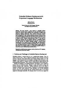
Memory map Unlike most previous ARM cores, the overall layout of the memory map of a device based around the Cortex-M3 is fixed. This allows easy porting of software between different systems based on the Cortex-M3. The address space is split into a number of different sections. This is shown in Figure 1 on page 4 and described in Table 2 on page 4.
ARM DAI0179B
Copyright © 2007. All rights reserved.
3
Application Note 179
�[(��)))))
520�WDEOH ([WHUQDO�33% (70 73,8
�[(��))��� �[(������� �[(������� �[(�������
�[))))))))
9HQGRU�VSHFLILF �[(������� �[(��)))))
3ULYDWH�SHULSKHUDO�EXV��H[WHUQDO �[(���)))) �[(���)��� �[(���(���
�[(������� �[(���))))
3ULYDWH�SHULSKHUDO�EXV���LQWHUQDO �[(������� �[')))))))
5HVHUYHG 6\VWHP�FRQWURO�VSDFH 5HVHUYHG )3% ':7 ,70
�[(������� �[(������� �[(������� �[(�������
([WHUQDO�GHYLFH
���*%
�[$������� �[�)))))))
�[��))))))
��0%
([WHUQDO�5$0
%LW�EDQG�DOLDV
���*%
�[�������� �[��))))))
�[�������� �[�)))))))
��0% �[�������� �[��������
�0%
3HULSKHUDO
%LW�EDQGLQJ
���*% �[�������� �[�)))))))
�[��))))))
��0%
%LW�EDQG�DOLDV
65$0
���*%
�[�������� �[��))))))
�[�������� �[�)))))))
��0%
&RGH
�[�������� �[��������
�0%
���*%
%LW�EDQGLQJ
�[��������
Figure 1 Cortex-M3 memory map Table 2 Details of Cortex-M3 memory map
4
Memory Region
Description
Accessed via bus
code
For code memory (flash, ROM, or remapped RAM).
ICode and DCode
SRAM
For on-chip SRAM with bit-banding feature.
system
peripheral
For normal peripherals with bit-banding feature.
system
external RAM
For external memory.
system
Copyright © 2007. All rights reserved.
ARM DAI0179B
Application Note 179
Table 2 Details of Cortex-M3 memory map (continued)
ARM DAI0179B
Accessed via bus
Memory Region
Description
external device
Memory space for external peripherals or shared memory.
system
private peripheral
Address space for system devices such as MPU, NVIC, DAP, and other CoreSight devices.
system
vendor specific
For additional uses specified by the vendor.
.
Copyright © 2007. All rights reserved.
5
Application Note 179
2
Developing software for Cortex-M3 This section describes the different aspects of developing software for the Cortex-M3 and demonstrates how to write code to configure and use the main features of the core. The code examples in this section are designed for use with the RealView Compilation Tools (RVCT) 3.0 or later.
2.1
Exception handling
Writing the exception table The easiest way to populate the vector table is to use a scatter file to place a C array of function pointers at memory address 0x0. The C array can be used to configure the initial stack pointer, image entry point and the addresses of the exception handlers. Example 1 Example C structure for exception handlers /* Filename: exceptions.c */ typedef void(* const ExecFuncPtr)(void) __irq; /* Place table in separate section */ #pragma arm section rodata="exceptions_area" ExecFuncPtr exception_table[] = { (ExecFuncPtr)&Image$$ARM_LIB_STACKHEAP$$ZI$$Limit, (ExecFuncPtr)__main, /* Initial PC, set to entry point */ NMIException, HardFaultException, MemManageException, BusFaultException, UsageFaultException, 0, 0, 0, 0, /* Reserved */ SVCHandler, DebugMonitor, 0, /* Reserved */ PendSVC,SysTickHandler, /* Configurable interrupts start here...*/ InterruptHandler0, InterruptHandler1, InterruptHandler2 /* … */ }; #pragma arm section
Note Note that the first two items in this structure are the initial stack pointer and the image entry point. The initial stack pointer is generated using a linker defined symbol. See Stack and heap configuration on page 11 for details. Example 1 uses the C library entry point (__main) as the entry point for the image.
6
Copyright © 2007. All rights reserved.
ARM DAI0179B
Application Note 179
The exception table has also been placed in its own section. This has been done using #pragma arm section rodata="exceptions_area". This directive instructs the compiler to place all the RO (read-only) data between #pragma arm section rodata="exceptions_area"and #pragma arm sectioninto its own section called exceptions_area. This section can then be referred to in the scatter file. The exception table is then placed at the correct location in the memory map, at address 0x0. Writing the exception handlers The core saves the system state when an exception occurs and restores it on return. The exception handlers do not therefore need to save or restore the system state and can be written as an ordinary ABI-compliant C function. However, we recommend that you use the __irq qualifier to aid clarity of code. The keyword is also used by the compiler to maintain eight-byte alignment of the stack where necessary. See Eight byte stack alignment on page 13 for further details. Example 2 Simple C exception handler __irq void SysTickHandler(void) { printf("----- SysTick Interrupt -----"); }
Note Clearing of an interrupt source must be handled by the ISR. On the Cortex-M3, exception prioritization, nesting of exceptions, and saving of corruptible registers is handled entirely by the core to permit efficient handling. This means that interrupts remain enabled by the core on entry to every exception handler. Placing the exception table Because the exception table has been placed in its own section in the object it can be easily placed at 0x0 using a scatter file as shown in Example 3. Example 3 Placing exception table in scatterfile LOAD_REGION 0x00000000 0x00200000 { ;; Maximum of 256 exceptions (256*4 bytes == 0x400) VECTORS 0x0 0x400 { exceptions.o (exceptions_area, +FIRST) } }
Note +FIRST is used to ensure that exceptions_area is placed at the very beginning of the region. It also prevents the vector table from being removed by the unused section elimination mechanism of the linker.
ARM DAI0179B
Copyright © 2007. All rights reserved.
7
Application Note 179
Configuring the System Control Space (SCS) registers The SCS registers are located at 0xE000E000. As there are a large number of individual registers, it is best to use a structure to represent them. This can then be positioned in the correct memory location by adding this structure to the scatter file, using a similar method to the exception table. Example 4 shows an example structure for the SCS registers. Example 4 SCS Register Structure typedef int int int
volatile struct { MasterCtrl; IntCtrlType; zReserved008_00c[2]; /* Reserved space */ struct { int Ctrl; int Reload; int Value; int Calibration; } SysTick; int zReserved020_0fc[(0x100-0x20)/4]; /* Reserved space */ /* Offset 0x0100 */ struct { int Enable[32]; int Disable[32]; int Set[32]; int Clear[32]; int Active[64]; int Priority[64]; } NVIC; int zReserved0x500_0xcfc[(0xd00-0x500)/4]; /* Reserved space */ /* Offset 0x0d00 */ int CPUID; int IRQcontrolState; int ExceptionTableOffset; int AIRC; int SysCtrl; int ConfigCtrl; int SystemPriority[3]; int SystemHandlerCtrlAndState; int ConfigurableFaultStatus; int HardFaultStatus; int DebugFaultStatus; int MemManageAddress; int BusFaultAddress; int AuxFaultStatus; int zReserved0xd40_0xd90[(0xd90-0xd40)/4]; /* Reserved space */ /* Offset 0x0d90 */ struct { int Type; int Ctrl; int RegionNumber; int RegionBaseAddr;
8
Copyright © 2007. All rights reserved.
ARM DAI0179B
Application Note 179
int RegionAttrSize; } MPU; } SCS_t;
Note This register structure might not contain all of the SCS registers in your device. See the reference manual provided by the silicon manufacturer of your device.
Configuring individual IRQs Each IRQ has an individual enable bit in the Interrupt Set Enable Registers, part of theNVIC registers. To enable an interrupt you need to set the corresponding bit in the Interrupt Set Enable Register. See the reference manual provided by the silicon manufacturer of the device you are using for specific details on the Interrupt Set Enable Register. Example 5 shows interrupt enable code for the SCS structure shown in Example 4 on page 8. Example 5 IRQ enable function void NVIC_enableISR(unsigned isr) { /* The isr argument is the number of the interrupt to enable. */ SCS.NVIC.Enable[ (isr/32) ] = 1