Apr 9, 2000 - sufficient service life for brick, sandstone and arenaceous marl masonry. Common ...... clock tower at the main entrance of the building. Since VI ...
Structural Studies, Repairs and Maintenance of Heritage Architecture XI
303
Application of a combined computational-experimental approach for the service life estimate of exterior plasters of historical buildings V. Kočí1, J. Maděra1, R. Černý1 & P. Rovnaníková2 1
Czech Technical University in Prague, Faculty of Civil Engineering, Department of Materials Engineering and Chemistry, Czech Republic 2 Brno University of Technology, Faculty of Civil Engineering, Institute of Chemistry, Czech Republic
Abstract A combined computational-experimental approach for estimating the damage of surface layers of historical buildings is presented in this paper. In the experimental part, the durability of selected plasters is assessed in terms of their frost resistance. In the computational part, a diffusion-type model of coupled heat and moisture transport is used for the identification of the number of frost cycles in a real structure. As a practical example, a historical wall with interior and exterior plasters is chosen. Three types of historical materials of load-bearing structure and three types of plasters are under consideration. The computational and experimental results show that a typical commercial renovation plaster has a sufficient service life for brick, sandstone and arenaceous marl masonry. Common lime plaster can be successfully applied on brick or arenaceous marl only. Hydrophobic lime plaster modified by metakaolin can be recommended for brick or sandstone masonry. Keywords: service life estimate, experimental analysis, computational analysis, heat and moisture transport.
1
Introduction
The current practice to the solution of the problem of damage of surface layers of historical buildings is based more or less on the method of analogy. At a WIT Transactions on The Built Environment, Vol 109, © 2009 WIT Press www.witpress.com, ISSN 1743-3509 (on-line) doi:10.2495/STR090271
304 Structural Studies, Repairs and Maintenance of Heritage Architecture XI reconstruction, usually such material and method of its application is used which is according to the meaning of supervisory authorities compatible with the original treatments and which already was found to be suitable at an application on some other building before. The durability of new surface layers is mostly estimated on the basis of experience, because too few parameters are known for a reliable durability estimate. The choice of a material for reconstruction is then often less suitable regarding the moisture and salt content in the masonry, which leads to low durability and short service life of surface layers. Many papers about the durability and conservation of historical building materials have been published to (see, e.g., [1, 2]). Some authors try to extend durability of historical building materials by protecting them from the effects of chemical substances contained in the atmosphere. They use mechanical or chemical cleaning or try to apply chemical products [3, 4]. From the point of view of extending durability of building materials it has been realized that material combination has a significant influence [5–7]. The combination of different materials can lead to damage caused by moisture circulation through the interface between materials [8]. Most of the referenced work is based only on experimental techniques. In this paper we use a combined computational-experimental approach as a new effective tool to estimate durability of building materials in construction. At present, there is no unified method to determine the service life of building materials taking into account all the influences. Most authors are focused on a limited number of selected parameters (chemical, mechanical, salt crystallization etc.). In this paper, we focused on the effects of freezing water. The prediction of moisture and temperature fields in envelope parts of historical buildings in a sufficiently long time makes it possible not only for a reliable analysis of durability of surface layers on the basis of a sufficient amount of input parameters, but also for a design of the time schedule of repeated repairs. It can also offer to the supervisory authorities alternative solutions of surface layers, taking into account their durability and financial demand.
2
Experimental
Ceramic brick, sandstone and arenaceous marl were chosen as representative materials of historical load-bearing walls. As for the plasters, lime plaster (LP), hydrophobic lime plaster modified by metakaolin (LPMH) and commercial twolayer renovation lime plaster (LPD) were analyzed. In the experimental work, the frost resistance of chosen plasters was investigated in laboratory conditions. The specimens had a size of 40×40×160 mm. After removal from the moulds they were placed into open boxes and humidified once per day until the end of the 28-days curing period. Temperature in the laboratory was 21±1°C, relative humidity was 45±5%. In order to measure freeze-thaw resistance of plasters, the water saturated testing specimens were cyclically frosted and defrosted until their damage got obvious. Three testing specimens of every plaster were put into drinking water of 201°C until their full saturation. After that, the specimens were removed from WIT Transactions on The Built Environment, Vol 109, © 2009 WIT Press www.witpress.com, ISSN 1743-3509 (on-line)
Structural Studies, Repairs and Maintenance of Heritage Architecture XI
305
water, wiped by paper towel and put into plastic bag. Packed specimens were put into freezing box for 6 hours. After removal, the specimens were kept in lab with temperature of 201°C for 2 hours, then were put into water bath for 16 hours. This cycle was repeated until the visible damage of specimens. Number of freezing cycles causing damage of plasters is summarized in Table 1. The two sub columns in LPD plaster column correspond to its two layers; SG 68 is the base layer and SP 64 G the external layer. Damage of LPD plaster (SG 68) is shown in Figure 1.
3
Computational
3.1 Description of construction The load-bearing wall was assumed to have a thickness of 500 mm. It was provided with 10 mm thick interior plaster and 20 mm thick exterior plaster. Materials of interior and exterior plasters were the same for LP and LPMH. In the case of LPD, we used lime plaster on interior side. Overall thickness of twolayer LPD plaster was 40 mm (2×20 mm). Material combination with investigated points in plasters is shown in Figure 2. Table 1:
Number of freezing cycles causing damage of plasters.
Number of freezing cycles
Figure 1:
LP
LPMH
8
40
LPD SG 68 SP 64 G 85 63
Damage of LPD (SG 68) after 85 cycles.
WIT Transactions on The Built Environment, Vol 109, © 2009 WIT Press www.witpress.com, ISSN 1743-3509 (on-line)
306 Structural Studies, Repairs and Maintenance of Heritage Architecture XI 3.2 Input parameters Basic material characteristics of analyzed materials are shown in Tables 2 and 3. We used the following symbols: ρ – bulk density [kg/m3], porosity%], c – specific heat capacity [J/kgK], μ – water vapour diffusion resistance factor [-], λdry – thermal conductivity in dry conditions [W/mK], λsat – thermal conductivity in water saturated conditions [W/mK], - moisture diffusivity [m2/s], whyg – hygroscopic moisture content by volume [m3/m3]. All these parameters were measured in Laboratory of Transport Processes of the Department of Materials Engineering and Chemistry, Faculty of Civil Engineering, Czech Technical University in Prague [9–11].
Figure 2: Table 2:
ρ [kg/m3] %] c [J/kgK] μdry cup [-] μwet cup [-] λdry [W/mK] λsat [W/mK] [m2/s] whyg [m3/m3]
Material combinations.
Material characteristics of plasters. LP
LPMH
1650 36.7 910 9.0 8.0 0.763 1.98 4.1e-7 0.0495
1745 33.2 915 15.0 14.0 0.845 2.40 3.9e-8 0.0240
LPD SG 68 1240 52.9 1380 16.0 13.5 0.34 1.55 4.1e-9 0.007679
WIT Transactions on The Built Environment, Vol 109, © 2009 WIT Press www.witpress.com, ISSN 1743-3509 (on-line)
SP 64 G 1175 54.6 1140 18.0 17.0 0.25 1.0 7.0e-10 0.031146
Structural Studies, Repairs and Maintenance of Heritage Architecture XI
Table 3: 3
ρ [kg/m ] %] c [J/kgK] μ [-] λdry [W/mK] λsat [W/mK] [m2/s] whyg [m3/m3]
307
Material characteristics of masonry. Brick 1746 35.0 960 22.5 0.763 1.980 3.0e-7 0.015
Sandstone 1807 31.0 850 7.5 1.100 3.650 2.5e-6 0.00567
Arenaceous marl 1400 63.1 837 5.0 0.710 0.890 1.0e-8 0.01
As boundary conditions in the exterior we used climatic data for Prague in the form of a Test Reference Year (TRY), which contains hourly values of average climatic data for 30 years. On the interior side we used constant values of relative humidity and temperature, 55% and 21°C, respectively. The simulation started on 1 July and was done for 3 years. 3.3 Computational model The computations were accomplished by the computational program TRANSMAT 7.1, which was developed at the Department of Material Engineering and Chemistry, Faculty of Civil Engineering, Czech Technical University in Prague on the basis of the general finite element package SIFEL [12]. The mathematical formulation of coupled transport of heat and moisture leads to a system of partial differential equations, which are solved by finite element method. In the particular case in this paper, Künzel’s model was used [13]:
d v div D grad p grad ps d t
(1)
dH T divgradT Lv div p grad p s dT t
(2)
where v is the partial density of moisture, relative humidity, p permeability of water vapour, ps partial pressure of saturated water vapour, H enthalpy density, Lv heat of evaporation, thermal conductivity and T temperature,
D Dw
d v d
(3)
is liquid moisture diffusivity coefficient and DW is the capillary transport coefficient. WIT Transactions on The Built Environment, Vol 109, © 2009 WIT Press www.witpress.com, ISSN 1743-3509 (on-line)
308 Structural Studies, Repairs and Maintenance of Heritage Architecture XI 3.4 Results of computational simulation The results of computational simulations are summarized in a set of figures. Every figure shows time dependence of moisture and temperature at the same time during the second year of simulation. This is advantageous with regard to interpretation of simulation results. There are two horizontal lines in each figure which represent hygroscopic moisture content of a particular plaster and temperature of freezing point of water. At the simultaneous overrun of these limits, convenient conditions for freezing cycle are arising. From the vast number of figures produced in computational simulations only the most representative are chosen, the rest of them are only described. 3.4.1 Brick masonry There are not any freezing cycles in LP applied on brick masonry because of low moisture content. This is obvious in Figure 3, which captures hygrothermal performance in point B. 650 0.2
700
750
800
850
270 0.1
260 250
0.05
Temperature [K]
280
0.15
3
3
Moisture content [m /m ]
290
240 0 650
Figure 3:
700
750 Time [days]
800
230 850
Hygrothermal performance in point B of LP applied on brick masonry.
A specific behaviour can be observed for VOMH applied on brick masonry. On the interface between the plaster and load bearing structure, there are not any freezing cycles because of low moisture content, but on the surface of plaster, there are many variations in moisture content in summer months as we can see in Figure 4. We counted one freezing cycle during a reference year in 691st day which took 13 hours. Moisture content in the internal layer of LPD is too low to creation of freezing cycle. However the same we cannot say about the external layer. There was one freezing cycle arisen in the 691st day and took 14 hours. This can be seen in Figure 5. WIT Transactions on The Built Environment, Vol 109, © 2009 WIT Press www.witpress.com, ISSN 1743-3509 (on-line)
Structural Studies, Repairs and Maintenance of Heritage Architecture XI
650
700
750
800
309
850 290
3
0.2 0.15
260
0.1
250
0.05
240
0 650
Figure 4:
270
700
750 Time [days]
800
Temperature [K]
280
3
Moisture content [m /m ]
0.25
230 850
Hygrothermal performance in point B of LPMH applied on brick masonry. 650
700
750
800
850 290
3
0.2 0.15
260
0.1
250
0.05
240
0 650
Figure 5:
270
700
750 Time [days]
800
Temperature [K]
280
3
Moisture content [m /m ]
0.25
230 850
Hygrothermal performance in point D of LPD applied on brick masonry.
3.4.2 Arenaceous marl masonry LP did not offer suitable conditions for creation of freezing cycle. This is given by low moisture content in all the thickness. In Figure 6 we can see that water contained in VOMH applied on arenaceous marl masonry got frozen three times on the interface between the plaster and load bearing structure during a reference year. The first cycle was arisen in 690th day and took one hour. The second cycle followed after 5 hours and took 4 WIT Transactions on The Built Environment, Vol 109, © 2009 WIT Press www.witpress.com, ISSN 1743-3509 (on-line)
310 Structural Studies, Repairs and Maintenance of Heritage Architecture XI hours, the last cycle after another 7 hours and took 2 hours. On the surface there were only two cycles which took 13 and 19 hours with 4 hour-lag between them. Water contained in the internal layer of LPD did not get frozen anytime, which is presented in Figure 7. Hygrothermal performance of external layer of LPD was similar to Figure 5, and there was one freezing cycle in 690th day which took 24 hours. 650 0.1
700
750
800
850
0.08
3
260
0.04
250 0.02
0 650
Figure 6:
270
0.06
Temperature [K]
280
3
Moisture content [m /m ]
290
240 700
750 Time [days]
800
230 850
Hygrothermal performance in point A of LPMH applied on arenaceous marl masonry. 650 0.03
700
750
800
850 290
3
0.02 0.015
260
0.01
250
0.005
240
0 650
Figure 7:
270
700
750 Time [days]
800
Temperature [K]
280
3
Moisture content [m /m ]
0.025
230 850
Hygrothermal performance in point B of LPD applied on arenaceous marl masonry.
WIT Transactions on The Built Environment, Vol 109, © 2009 WIT Press www.witpress.com, ISSN 1743-3509 (on-line)
Structural Studies, Repairs and Maintenance of Heritage Architecture XI 650 0.2
700
750
800
311
850
270 0.1
260 250
0.05
Temperature [K]
280
0.15
3
3
Moisture content [m /m ]
290
240 0 650
Figure 8:
700
750 Time [days]
800
230 850
Hygrothermal performance in point B of LP applied on sandstone masonry. 650 0.1
700
750
800
850
0.08
3
260
0.04
250 0.02
0 650
Figure 9:
270
0.06
Temperature [K]
280
3
Moisture content [m /m ]
290
240 700
750 Time [days]
800
230 850
Hygrothermal performance in point A of LPMH applied on sandstone masonry.
3.4.3 Sandstone masonry Only sandstone masonry provided with LP gave suitable conditions to creation of freezing cycle. There were two cycles on the surface in 690th and 691st day which took 12 and 22 hours. This is shown in Figure 8. LPMH applied on sandstone masonry showed high moisture content differences on the surface again. This led to creation of three freezing cycles in 690th and 691st day of simulation which took 16, 22 and 4 hours. One cycle was counted in 691st day on the interface between the plaster and load bearing structure, too and took 10 hours (Figure 9). WIT Transactions on The Built Environment, Vol 109, © 2009 WIT Press www.witpress.com, ISSN 1743-3509 (on-line)
312 Structural Studies, Repairs and Maintenance of Heritage Architecture XI 650
700
750
800
850 290
3
0.2 0.15
260
0.1
250
0.05
240
0 650
Figure 10:
270
700
750 Time [days]
800
Temperature [K]
280
3
Moisture content [m /m ]
0.25
230 850
Hygrothermal performance in point D of LPD applied on sandstone masonry.
Due to the low moisture content the internal layer of LPD applied on sandstone masonry cannot be damaged by freezing water. However, water contained in external layer of LPD reached overhygroscopic state simultaneously with temperature below zero twice a year. So, we could count two freezing cycles in 690th and 691st day which took 33 and 7 hours (Figure 10).
4
Discussion
In this paper, we assumed phase changes of water as the only factor affecting the service life of exterior plasters. This is certainly a simplification of the reality on building site but separation of this particular effect from the variety of others can provide valuable information indeed. In case of brick masonry, as the best combination with regard to frost resistance was to apply LP or LPMH. Lime plaster did not get frozen anytime during the reference year because water contained in plaster did not reach overhygroscopic state. Hydrophobic lime plaster modified by metakaolin got frozen during the reference year, but this happened only on the surface of plaster thanks to hydrophobic modification. So, the destruction effect of freezing water was minimized and this material combination can be recommended for practical use. Apparently, the service life of these two material combinations will be not limited by frost resistance. Internal layer of LPD did not get frozen, but the external layer was exposed to freezing water once during the reference year due to its lower moisture diffusivity. If we assumed only this impact on service life, we could estimate it to 60 years.
WIT Transactions on The Built Environment, Vol 109, © 2009 WIT Press www.witpress.com, ISSN 1743-3509 (on-line)
Structural Studies, Repairs and Maintenance of Heritage Architecture XI
313
Arenaceous marl masonry has relatively high porosity and low moisture diffusivity. Therefore, it can hold contained water for a longer time. This is the reason why we counted more cycles on the interface between the plaster and load bearing structure than on the surface of LPMH; water could get into the plaster not only from the exterior but from the masonry, too. Service life of this material combination can be estimated to 20 years. Behaviour of LPD applied on arenaceous marl masonry was very similar to LPD applied on brick masonry. We counted only one freezing cycle in external layer, so the lifetime can be estimated to 60 years. Best results gave the material combination of arenaceous marl masonry with LP. Overhygroscopic moisture content was reached only in summer months when the temperature was over zero, so there were not any freezing cycles during the reference year. The frost resistance will be not the limiting factor for service life. Application of LP on sandstone masonry cannot be recommended. There were counted two freezing cycles in surface layer of the plaster in this material combination. This will lead to degradation of plaster after 4-8 years in dependence on its thickness. Hydrophobic lime plaster modified by metakaolin applied on sandstone masonry got frozen once a reference year on the interface between the plaster and load bearing structure and three times on the surface. This means, at least once a year the plaster got frozen in all the thickness and the service life could by estimated to 30 years at most. In case of LPD, internal layer was protected from effects of freezing water thanks to low moisture content. However, the external layer was exposed to two freezing cycles during the reference year. Service life of this plaster is about 30 years.
5
Conclusions
In an assessment of the impact of freezing cycles on the service life of exterior plasters it is necessary to find how many cycles can arise during one year and take it into account during service life estimation. As we can see from the simulation results presented in this paper, it is important to bear in mind that number of freezing cycles depends not only on material properties of a particular plaster but also on the material of load bearing structure. Among the walls of historical buildings investigated in this paper, from the point of view of frost resistance the best combination was a common lime plaster (LP) with brick or arenaceous marl masonry. In these cases, water in the plaster did not get frozen anytime. The service life of commercial renovation plaster (LPD) was for both brick and arenaceous marl masonry 60 years which was quite sufficient. The hydrophobized lime plaster with metakaolin (LPMH) performed without any problems for brick masonry; its service life for arenaceous marl was 20 years. Sandstone walls presented the most difficult case for all studied plasters. LP as a material for reconstruction of this type of wall should be avoided because its service life would be only 4-8 years. On the other hand, LPMH or LPD could serve for approximately 30 years which was acceptable.
WIT Transactions on The Built Environment, Vol 109, © 2009 WIT Press www.witpress.com, ISSN 1743-3509 (on-line)
314 Structural Studies, Repairs and Maintenance of Heritage Architecture XI
Acknowledgement This research has been supported by the Czech Science Foundation, under grant No 103/09/0780.
References [1] Price, C.A., Stone Conservation: An Overview of Current Research, Getty Conservation Institute: Santa Monica, pp. 1–86, 1996. [2] Esbert, R.M., Montoto M., Jordaz G., Rock as a construction material: durability, deterioration and conservation. Materiales de Construcción, Vol. 41, pp. 61–73, 1991. [3] Gómez Heras M., Alvarez de Buergo M., Rebollar E., Oujja M., Castillejo M., Fort R., Laser removal of water repellent treatments on limestone. Applied Surface Science, Vol. 219, pp. 290–299, 2003. [4] Amoroso G., Fassina V., Stone Decay and Conservation: Atmospheric Pollution, Cleaning, Consolidation and Protection, Elsevier Science Ltd: Amsterdam, pp. 1–474, 1983. [5] Lu G., Lu G.Q., Xiao Z.M., Mechanical properties of porous materials. Journal of Porous Materials, Vol. 6, pp. 359 –368, 1999. [6] Larbi J.A., Microscopy applied to the diagnosis of the deterioration of brick masonry. Construction and Building Materials, Vol. 18, pp. 299–307, 2004. [7] Lu G., Lu G.Q., Xiao Z.M., Mechanical properties of porous materials. Journal of Porous Materials, Vol. 6, pp. 359–368, 1999. [8] Mendes N., Philippi P.C., A method for predicting heat and moisture transfer through multilayered walls based on temperature and moisture content gradients. International Journal of Heat and Mass Transfer, Vol. 48, pp. 37–51, 2005. [9] Pernicová, R., Keppert, M., Černý, R., Pavlíková, M., Studium omítek pro sanaci historických objektů. Stavební obzor, Vol. 8, pp. 230-235, 2008. [10] Jiřičková, M., Application of TDR Microprobes, Minitensiometry and Minihygrometry to the Determination of Moisture Transport and Moisture Storage Parameters of Building Materials, CTU: Prague, pp. 1–102, 2004. [11] Pavlík, Z., Michálek, P., Pavlíková, M., Černý, R., Kopecká, I., Maxová, I., Water and salt transport and storage properties of Mšené sandstone. Construction and Building Materials, Vol. 22, pp. 1736–1748, 2008. [12] Maděra, J., Černý, R., TRANSMAT – A computer simulation tool for modeling coupled heat and moisture transport in building materials. Proceedings of Workshop 2005, CTU: Prague, pp. 470-471, 2005. [13] Künzel, H.M., Simultaneous Heat and Moisture Transport in Building Components, Ph.D. Thesis, IRB Verlag: Stuttgart, pp. 1–135, 1995.
WIT Transactions on The Built Environment, Vol 109, © 2009 WIT Press www.witpress.com, ISSN 1743-3509 (on-line)
Structural Studies, Repairs and Maintenance of Heritage Architecture XI
315
Morphology of a canopy as a preservation structure I. Markov & P. Bhiwapurkar School of Architecture, Rensselaer Polytechnic Institute of Technology, USA
Abstract New technologies have enriched the exploration of architectural designs and ideas. New tools, such as parametric modelling, have enabled architects to investigate designs of “free forms” and shapes of unseen complexity in the past. Rapid prototype models provided new means to examine tectonics and spatial qualities. Yet these “free-morphologies” must recognize constrains of performance needs. This investigation explores a morphology with respect to structural and lighting performance. Structural performances are assessed by finite element analyses by generating stress distributions under typical loads and specific boundary conditions. The evaluation of lighting performance is assessed by evaluating the illumination level on a specified surface area. In the past, build examples show separation of the language of envelope and the language of supporting structure. Here an attempt is made to bring the harmony and blend the two different articulations. The concept is tested in architectural curricula on a real case design scenario of a preservation canopy for Yungang Grottoes in Datong, Shanxi Province, China that has recently been declared a UNESCO world heritage site. Keywords: structure, morphology, free-form, performance, stress, lighting, illumination, daylight, Yungang Grottoes, UNESCO.
1
Introduction
Preservation of cultural heritage is attracting attention in today’s China. Designs are becoming more sophisticated using digital tools that provide new media in which to generate and explore, contributing to the development of common methods and enriching the means available in the design of contemporary architectonics. The growing presence of these tools is evident not only in the designs of signature buildings, but also in the preservation of historic sites. WIT Transactions on The Built Environment, Vol 109, © 2009 WIT Press www.witpress.com, ISSN 1743-3509 (on-line) doi:10.2495/STR090281
316 Structural Studies, Repairs and Maintenance of Heritage Architecture XI Parametric modelling software enables the creation of forms of previously unseen complexity and combined with 3-D printers allows production of complex physical models for the visualization of ideas, and reveals in-depth tectonics and spatial qualities. Some of the resulting forms are fully free-forms; however, for the complex forms to be realized they must meet their structure and performance criteria. The conceptual investigation presented here focuses on the structural and lighting evaluation of a free-form canopy as a potential solution for preservation of historic sites. Structural performance is assessed using finite element analysis to generate the stress distribution under typical loads and assigned support conditions. A decrease in the critical stress field is treated as an increase in structural efficacy. The lighting performance is assessed by the level of illumination in the critical plane. This investigation seeks to achieve harmony and to blend articulation of the envelope with articulation of the structure, presenting a concept for the masscustomization of free-forms. The search for the form is driven by spatial and structural effectiveness. Parametric modelling and structural analysis software were combined to balance creativity with efficiency. The case study is rooted in the Chinese context. It is first tested in the teaching environment and then explored in research studies. The study contributes to challenge how to “meaningful” explore digitally generated forms during the conceptual stage of preservation designs.
2
Study of the form
The tectonics of a large volume needed on historic sites is articulated by the generative surface, which can be used to create remarkable spatial conditions. In addition to spatial considerations, the design of the surface form must take into account technical considerations, including structural performance, and illumination conditions. The larger the scale of the project, the greater the importance of these considerations. A generative surface is tested in a real case design of a space frame canopy for the Yungang Grottoes in Datong, Shanxi Province, China, which has recently been declared a UNESCO World Heritage Site. The grottoes were built around AD 450, and extend for about 1 km along a mountain ridge, consisting of 53 grottoes that contain approximately 51,000 statues ranging in size from 2 cm to 17 m. Over the past 1500 years, the statues have been exposed to human damage and erosion by water and wind, resulting in severe decay. The Chinese Government has recently initiated a project to protect the Yungang Grottoes by the construction of a shelter. The focus of the present exploration is the tallest Buddha in Grotto No. 5, which is surrounded by many small Buddhas. As part of the present study, graduate students from the Department of Architecture, Chinese University of Hong Kong, visited the site and subsequently explored design alternatives for a shelter in the techniques thematic design studio. The mountain ridge that houses the grottoes is 20 m high, and one
WIT Transactions on The Built Environment, Vol 109, © 2009 WIT Press www.witpress.com, ISSN 1743-3509 (on-line)
Structural Studies, Repairs and Maintenance of Heritage Architecture XI
Figure 1:
317
Proposed mushroom canopy to protect Buda statue.
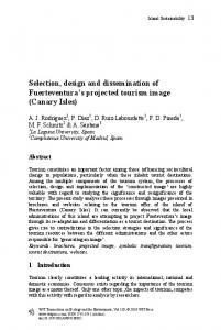
of the requirements is that the shelter it is not supported by this ridge. This requirement is an important consideration because the proposed structure should not read as part of the historic site, as they have no common culture. Moreover, the ridge could not be used to provide reliable support without the need for major intervention. The proposition shown in fig. 1 was selected for further investigation. The stated intent of maintaining the site in its unattached state while adding a shelter is somewhat self-contradictory, as any new structure would strongly alter the site. Therefore, the response of the new structure to the site conditions was set as a primary goal in architectural articulation. Any shelter would have to enable visitors to sense the site’s uniqueness, heritage, religious and spiritual values. A canopy consist of a number of columns yet only three “mushroom” columns are in front of the largest Buda and were part of this investigation as shown in fig. 2. The columns vary in size and shape. The plane of the roof mirrors the form of the ridge, and the columns take the form of pointed arches, thereby highlighting the Buddhas and directing the visitor’s observation in their direction. The structure of the canopy is anticipated as essentially a steel space frame. Such a structure offers light and transparent, yet strong enough system to cover a large volume and respond to large snow loads. Stress fields were used to tune the curves of the canopy plane and shape the parametrically designed “mushroom” columns in order to improve the performance of the entire assembly. A number of areas were identified as having the highest stress concentrations. The curvatures of the plane were iteratively distorted, and at each step the structure was checked to assess whether the critical stress levels had improved or worsened. As the final solution, a more efficient geometry was selected that did not compromise the architectural intent. Figure 2 shows the results after the process was completed for adjusting the curvatures of the canopy plane.
WIT Transactions on The Built Environment, Vol 109, © 2009 WIT Press www.witpress.com, ISSN 1743-3509 (on-line)
318 Structural Studies, Repairs and Maintenance of Heritage Architecture XI
Figure 2:
Model mesh and stress distribution after completion of the adjustment process.
In addition to the areas of high stress concentration the figure also reveals areas of low stresses. At the areas of low stress in the structure, the material is not used efficiently and may be removed or replaced by transparent, nonstructural panels. The process of removal of the material subjected to low stresses was carried out manually in an iterative fashion. At each step, those plates subjected to the lowest stresses were removed and the remaining structure was reanalyzed. In subsequent steps, a new set of plates appeared with low stresses, and these were removed in turn. Fig. 2 also shows the approximate shape of the structure after the plates had been removed. It is interesting to observe the locations of voids in the canopy and “mushroom” columns. The voids in the canopy allow for articulation with lighting panels, and openings in the columns might be used as entrances into architectural spaces programmed for services and shops. The envelope is anticipated as a partly transparent surface that can also contribute to the stability of the overall assemblage yet provide optimal light distribution on the face of the Buda statue. Exploration of lighting conditions was performed in conjunctions with structural exploration.
3
Daylighting study
A daylighting study is conducted to investigate the effect of a proposed canopy structure on illumination level inside the cave using three roofing materials; PVC polyester fabric, ethyl tetra fluoroethylene (ETFE) and polytetrafluoroethylene (PTFE). The largest cave of 50’x70’x50’ size is selected for this investigation. We focus on the illumination level on the face of the statue. Actual illumination plane is considered in line with the face as shown in fig. 3. Three mushroom columns which support a roof structure stand in front of this cave. The roof and side walls of this structure are central surfaces for this study. The opening of the cave is 50’ tall and 70’ wide which is the only source of daylight. This study mainly focuses the illumination levels on a plane of 8’x 8’ representing the face. This study is conducted for overcast sky conditions for December 21.
WIT Transactions on The Built Environment, Vol 109, © 2009 WIT Press www.witpress.com, ISSN 1743-3509 (on-line)
Structural Studies, Repairs and Maintenance of Heritage Architecture XI
319
Dec. 21 [1:00pm]
21’
Dec. 21 [10:00am] 10’ Dec. 21 [4:00pm]
3’ 5’
Face Roof Membrane
42’
Cave
Partial Site Map showing Cave Ca location in relation to the Canopy Structure
Side Membrane
Illumination Plane
Figure 3:
Daylighting study set-up.
The illumination level due to proposed roof/canopy structure is compared with the existing conditions on December 21 at 10am, 1pm and 4pm. The “Baseline” condition is represented by a cave without canopy/roof structure which is similar to the existing condition. First set of investigation is carried out for the effect of time on lighting conditions. The lighting simulations are performed for 10am [Baeline+1], 1pm [Baseline+2] and 4pm [Baseline+3] for overcast conditions as shown in table 1. The top and side fabric membranes are made up of PVC-polyester fabric and are considered constant for these alternatives. The reflectivity of fabric structure is 0.8 and transmittance is 0.2. Second set of investigations focus on materials and replaces the PVCpolyester fabric by ETFE and PTFE. Baseline+5 consider ETFE foil which is lightweight, highly transparent to UV light, is not degraded by sunlight, has better insulation properties than glass, is recyclable and can take up to 400 times its own weight. ETFE reflectivity is 0.95. Baseline+7 uses a PTFE membrane, which is a versatile, hydrophobic membrane available laminated to various support materials or unsupported. The reflectivity of this material is 0.9. The average illumination level for a baseline condition at 10am is 250.8 Footcandles (Fc) which is the highest amongst all studied configurations. This illumination level is an average of the all calculated illumination values inside the rectangular box shown in table 1. The average illumination level decreases by 69% (75.08Fc) at 10am for Baseline+1 condition when a proposed structural canopy which uses PVC-polyester fabric for roof and side wall is considered in front of the cave. The estimated illumination level at 1:00pm for [Baseline+2] is 72.13Fc. This reduction is 71% from the baseline conditions. At 4pm on December 21 on an overcast sky conditions, average illumination level is very low and accounts for 98% reduction from the baseline condition as shown in table 1. The PVC-Polyester fabric material as a source of diffused light is well established however overcast conditions during study period and low solar angle (26.7°-17°) are considered a major cause for reduction in natural light for this study. At low sun angles roof structure and importantly mushroom columns WIT Transactions on The Built Environment, Vol 109, © 2009 WIT Press www.witpress.com, ISSN 1743-3509 (on-line)
320 Structural Studies, Repairs and Maintenance of Heritage Architecture XI Table 1:
Comparative average illumination levels on December 21. Baseline [10pm]
Overcast Conditions Reflectivity and Transmittance
No Structure
Baseline-1 [10am] Structure PVC-Polyester Fabric
Baseline-2 [1pm] Structure PVC-Polyester Fabric
Baseline-3 [4pm] Structure PVC-Polyester Fabric
-
[0.8,0.2]
[0.8,0.2]
[0.8,0.2]
250.8 Fc
78.74 Fc
72.13 Fc
5.4 Fc
[100%]
[31%]
[29%]
[2%]
Average illumination level inside the rectangle
Illuminance [FootCandles]
blocks the natural daylight by addition of surface layers between sky and illumination plane. As a result, in Baseline+1 and Baseline+2 illumination levels on columns are much brighter than the receiving vertical plane. A marginal improvement in illumination level is observed when baseline condition is modified by changing roof and wall membrane properties. The average illumination level of Baseline+5 using ETFE is 5% (75.86 Fc) above Baseline+4 whereas with increase in lighting condition of Baseline+6 with PTFE is 2% (73.62 Fc) as shown in table 2. Although lighting levels are reduced by WIT Transactions on The Built Environment, Vol 109, © 2009 WIT Press www.witpress.com, ISSN 1743-3509 (on-line)
Structural Studies, Repairs and Maintenance of Heritage Architecture XI
Table 2:
Overcast Reflectivity and Transmittance
321
Comparative average illumination levels by change in roof and wall material properties. Baseline-4 (1pm) PVC Polyester Fabric
Baseline-5 (1pm) ETPE
Baseline-6 (1pm) PTFE
(0.8,0.2)
(0.95,0.05)
(0.9,0.1)
72.13 Fc
75.86 Fc
73.62 Fc
(100%)
(105%)
(102%)
Average illumination level inside the rectangle
canopy structures, the contrast between calculated highest and lowest illumination level on a vertical is relatively less compared to the baseline conditions thus reduces glare to certain extent. In addition, the contrast between top and lower portion of an illuminating surface needs attention for minimizing glare. The low solar angle illuminates lower portion of the cave while top portion of the cave remains relatively less illuminated due to the depth of the cave and obstruction by a structural canopy. During clear sky conditions contrast may even be higher however average illumination level increases by 10%. Therefore, a combination of opaque and transparent surfaces in response to the solar geometry may be a useful strategy for achieving uniform lighting conditions inside the cave.
WIT Transactions on The Built Environment, Vol 109, © 2009 WIT Press www.witpress.com, ISSN 1743-3509 (on-line)
322 Structural Studies, Repairs and Maintenance of Heritage Architecture XI A major limitation of this study is a simplified rectangular illumination plane considered for investigation of the illumination levels on a spherical face of the statue. Also, the study is performed during overcast sky conditions therefore these results do not take in to account the shading pattern by the structural canopy. The illumination levels will certainly be higher during partly cloudy and clear sky conditions. However, this study provides evidences that the roof structure can enhance the illumination levels inside the cave by adjusting the material properties according to the solar geometry. The roof and side wall material properties can be used to create uniform illumination levels to minimize glare and need for artificial illumination, if any. The roof membrane surface properties are significant to allow daylight and side membrane can be used for even distribution of diffused light. The curvature of roof and column structure can be a key parameter towards this effect. However, further investigations are required to test the effect of materials and structure to maximize average illumination levels on the top as well as sides of the structure during specific time of the day.
4
Conclusion
This study explored the concept of the efficiency of a generative surface for large-volume tectonics proposed for conservation of a heritage site. The form was adjusted slightly to enhance structural performance without compromising the architectural articulation. The adjustment was based on stress field distribution generated by FE analyses. Moreover, those materials not used efficiently in the structure were removed and replaced by transparent panels in the roof or left as voids to enable access into the columns. A design based on a generative surface was tested in a real case design scenario involving the design of a canopy to protect the Yungang Grottoes, China. Illumination level inside the cave is decreased due to proposed structural canopy by 69%, 71% and 98% at 10am, 1pm and 4pm during overcast conditions on December 21 using PVC-Polyester fabric material for roof and side walls. Other lightweight roof material ETFE and PTFE marginally improves the average illumination levels.
References [1] Markov, I.,” Free-Forms and Technical Efficacy” IASS-IACM 2008 "Spanning Nano to Mega", Cornell University, 28-31 May 2008, Ithaca, NY, USA. [2] ASAHI Glass Co. http://www.fluon.jp/fluon/english/products/etfe_film/ apply_01.html
WIT Transactions on The Built Environment, Vol 109, © 2009 WIT Press www.witpress.com, ISSN 1743-3509 (on-line)
Structural Studies, Repairs and Maintenance of Heritage Architecture XI
323
Application of the generic process modelling in the preservation of heritage school buildings Z. Abidin Akasah1 & M. Alias2 2
1
Faculty of Civil and Environmental Engineering, Malaysia Faculty of Technical Education, Malaysia
Abstract The preservation of heritage school buildings requires special maintenance management practices. A thorough understanding of the maintenance management process is essential in ensuring effective maintenance practices can be instituted. The aim of this research was to develop a generic process model that will promote the understanding of an effective management of maintenance process for heritage school buildings. A process model for the Maintenance Management of Heritage School Buildings (MMHSB) was developed using the Integration Definition for Function Modelling (IDEF0) system through an iterative process. The initial MMHSB process model was submitted to a team of management experts from the Malaysian Ministry of Arts and Heritage and the Ministry of Education Malaysia for verifications. Based on their feedback the initial model was refined and a proposed model was developed and sent to them for a second verification. The feedback received from the second verification formed the basis for the final model that was also validated by the same experts. The final model elucidates the items for the input, mechanism, control and output elements that are critical in the maintenance management of heritage school buildings. The model also redefines the existing scope of responsibilities of the Headmasters’ and Senior Assistants’ in the management of maintenance. The perceived effectiveness of the model by potential users was surveyed using a selected number of administrators from about to be recognised heritage schools. The results indicated that the process model is perceived as being helpful in clarifying the maintenance management process of heritage school buildings and is potentially useful in changing the current reactive management practices to that of a more proactive practice. In conclusion, the MMHSB Process Model is potentially helpful in promoting understanding of the maintenance management process, which would lead to improve preservation practices of heritage school buildings. Keywords: heritage school buildings, process modelling, maintenance management system. WIT Transactions on The Built Environment, Vol 109, © 2009 WIT Press www.witpress.com, ISSN 1743-3509 (on-line) doi:10.2495/STR090291
324 Structural Studies, Repairs and Maintenance of Heritage Architecture XI
1
Introduction
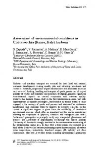
Heritage conservation in Malaysia has been considered as a new practice compared to the more developed countries in the world. Malaysia has inherited hundreds of heritage buildings; 181 buildings from the past including from the Indians, Chinese and Colonials era apart from the indigenous traditional buildings [1]. For school building, Victoria Institution (VI) which is one of the leading schools in the Klang Valley and the alma mater for some of the most influential and powerful Malaysians have been listed as the 1st National Heritage School on the 14th February 2009 [2]. VI was founded by Sultan Abdul Samad, William Hood Treacher, Loke Yew, Thamboosamy Pillai and Yap Kwan Seng on Aug 14, 1893. VI has played an important role in the nation’s history and it is also the second English high school in Malaya after Penang Free School [2, 3]. Since the Minister of Unity, Culture, Arts and Heritage, who happens to be an old boy of VI, has declared that the school can now revert to the old English name following the awarding of the National Heritage status, it would also be appropriate for the Minister to also consider other world-renowned and historically rich schools in the country, such as Penang Free School, to be accorded similar status. However Penang Free School (built in 1816) need to follow National Heritage Acts (2005) requirements before Unity, Culture, Arts and Heritage Ministry recognised as one of the heritage school building in Malaysia. Figure 1 shows the main entrance to VI. Whatever it is Unity, Culture, Arts and Heritage Minister called for the school’s heritage to be conserved as each characteristic “be it a wall, a window, balcony, roof, tower or its field has its own story”. Till today VI has maintained a record of academic excellence and produced many leaders and luminaries. Therefore VI should be prepared to maintain the status quo as before and in the future, especially related to building physical [4]. Figure 2 shows VI distinctive clock tower at the main entrance of the building. Since VI is the first recognised heritage school in Malaysia, an overview history of the building will be explained. This explanation is very important in order to relate the process of maintaining heritage building from deteriorating. VI history will alleviate the process of maintenance to be done to preserve heritage school building for comfort during teaching and learning in the future.
Figure 1:
Main building entrance of Victoria Institution (VI) [2, 3].
WIT Transactions on The Built Environment, Vol 109, © 2009 WIT Press www.witpress.com, ISSN 1743-3509 (on-line)
Structural Studies, Repairs and Maintenance of Heritage Architecture XI
Figure 2:
Victoria Institution’s distinctive clock tower [3].
Figure 3:
2
325
VI Building construction phase [5, 6].
Preservation process of VI heritage building
The present VI building dates from 1929. Before that the VI was located in High Street (now Tun H.S. Lee Road) in the heart of old Kuala Lumpur town where the school was first established in 1893. As the school grew over the decades, its environment also grew and changed, mirroring the parallel growth of Kuala Lumpur [5]. The building construction phase is shown in Figure 3. When Malaya government approved the establishment of the VI, eight acres of land on the left bank of the Klang River were set aside. The map of 1889 in Figure 3 shows a vastly different Kuala Lumpur from that of today. Construction began in 1893 of two buildings, one a school block known as Block 1 and the other a large bungalow for the Headmaster. Block 1 had two floors, the ground floor being mainly of brick while the upper part of the building was largely timber floor. The map of 1895 shows the school a year after it opened. Block 1 fronts High Street while the Headmaster's Bungalow is further away at the bend of the river. While the map of 1929 shows a vastly changed VI All the buildings that make up the school complex are in place [5, 6]. The map of 1939 in Figure 4 shows a significant change in the former VI complex.
WIT Transactions on The Built Environment, Vol 109, © 2009 WIT Press www.witpress.com, ISSN 1743-3509 (on-line)
326 Structural Studies, Repairs and Maintenance of Heritage Architecture XI
Figure 4:
Figure 5:
VI Building construction phase [5, 6].
Graphic visualization depicts VI in the late twenties [6].
The map of 1950 shows little change in the former VI complex five years after the World War II. Where as the map of 1961 shows a densely packed postMerdeka Kuala Lumpur, with buildings sprouting everywhere. The river has become a road [6]. Figure 5 shows a graphic visualization depicts VI at the end of a school day in the late twenties. While across the Klang River in the background is the Railway Station and facing the school (roof partly shown on left foreground) are the barracks of the High Street Police Station [6].
3
Fire safety maintenance process in heritage school
It has been accepted as a fact, that as school buildings become older, more fire protection is required. Hence, more people are placed at risk from fire than before [6]. An outbreak of fire in historic buildings often has more serious consequences than it has on a modern building. This is because of the large amount of timber in the construction of the building structure, while building fabric is weak in fire resistance. Such consequences happened to VI on the evening of July 26, 1999, a fire broke out in Block 1. The roof and wooden floor were destroyed although the concrete walls survived. The gable with "1893" WIT Transactions on The Built Environment, Vol 109, © 2009 WIT Press www.witpress.com, ISSN 1743-3509 (on-line)
Structural Studies, Repairs and Maintenance of Heritage Architecture XI
Figure 6:
Figure 7:
327
Effect of fire to Block 1 VI in 1999 [6].
VI heritage building after fire in 1999 [6].
inscribed on it and which had stood for 106 years was consumed by the flames. Such photograph as in Figure 6 below shows the incident where no.1 shows the skeletal remains of the porch facing High Street; no. 2 shows the southern façade with its small wooden porch and no. 3 shows the northern façade with part of the long curving porch most of which has been spared [6]. In the photograph in Figure 7, no. 4 shows the southern façade from the top of the stairs, no. 5 shows collapsed rafters on the first floor beams, no. 6 shows the ground floor with ubiquitous gothic arches in the background and no. 7 shows the ground floor with remains of partitioning that were probably of post-1960 vintage [7, 8]. Heritage buildings in Malaysia are considerable of architectural and historical importance and their destruction by fire is an irreplaceable loss. It should be well kept and protected from fire danger at all time. Lessons of major fires in heritage buildings such as Victoria Institution, is that every building should have a good fire resistance to prevent fire from outbreak [6, 8]. Fire resistance is one of the ways to minimise the outbreak of fire from destroying heritage buildings. Most heritage buildings is built with fire resistance materials, which is by today’s standards, fall far below the required performance with regard to Building Regulations and Fire Precautions Acts in Malaysia [7, 8]. Maintaining heritage school buildings in good condition through preventive measures make sense for academic, health as well as economic reasons [9, 10]. However, there appears to be a lack of preventive maintenance culture in general, not only in normal maintenance but also in maintenance of heritage building. One of the root causes of the problem is the lack of an understanding of the maintenance management process for heritage building among school WIT Transactions on The Built Environment, Vol 109, © 2009 WIT Press www.witpress.com, ISSN 1743-3509 (on-line)
328 Structural Studies, Repairs and Maintenance of Heritage Architecture XI administrators as such it hinder the schools from designing a good maintenance programme for their schools. Process mapping has been identified as one of the techniques that can facilitate one’s understandings of a process through a rigorous analysis of and an appropriate representation of the existing process using suitable mapping or modelling tool. Examples of process mapping tools include flow charts, Petri nets, Unified Modelling Language, the Integration Definition for Function Modelling (IDEF0). Thus next sub-topic will discuss the development of a process model for the management of heritage school buildings using the IDEF0 modelling system.
4
IDEF0 modelling system in heritage school building
IDEF is defining as the common name referring to classes of enterprise modelling languages. Whereas the objective of IDEF is to use for modelling activities necessary to support system analysis, design, improvement or integration. Besides that originally, IDEF was developed to enhance communication among people trying to understand the system. Now, IDEF is being used for documentation, understanding, design, analysis, planning, and Integration [11]. This IDEF0 generic modelling system is based on research done by Zainal Abidin Akasah (2007) for the Ministry of Education Malaysia. The same concept and framework applied for modelling heritage school buildings as due to the fact that VI management is in the same system and organisation. In the 1970’s, IDEF0 originated in the U.S. Air Force under the Integrated Computer Aided Manufacturing(ICAM) program from a well-established graphical language, the Structured Analysis and Design Technique (SADT). The IDEF0 modelling system is a structured design and analysis technique based on graphics syntaxes and semantics [12]. This system enables a designer to produce a process model that is descriptive as well as comprehensive. In the early 1980s the U.S National Institute of Standards Technology (NIST) published the system in the Federal Information Processing Standard as a manual under the topic of Integration Definition for Function Modelling (IDEF0). Through continuous improvements of the manual, the Institute of Electrical and Electronics Engineers (IEEE) established the IDEF0 standards (IEEE Std 1320.1-1998). Since then IDEF0 has been often used not only for process modelling but also for evaluation of current process models [13].
5
IDEF0 Procedures used in heritage building maintenance
Three main stages of process modelling in the IDEF0 system, (i) constructing a context model, (A-0 model), (ii) identifying the main activity from the A-0 activity (first decomposition to obtain A0 model) and (iii) identifying subactivity of the main activities in the A0 model (second decomposition). The IDEF0 system limits the number of decomposed activity to a minimum of three and a maximum of six. Each decomposed activity is labelled with a number WIT Transactions on The Built Environment, Vol 109, © 2009 WIT Press www.witpress.com, ISSN 1743-3509 (on-line)
Structural Studies, Repairs and Maintenance of Heritage Architecture XI
Figure 8:
329
Decomposition of a parent activity to its sub-activities [14].
according to the label of the parent activity. An IDEF0 diagram does not contain information on timing. Figure 8, illustrates how a parent activity is decomposed into its sub-activity and links together the context diagrams [14].
6
Development of generic heritage building maintenance management process model
The generic heritage building maintenance management process model (HBMM Process Model) was developed in three main stages, 6.1 Stage I - gathering of information 6.2 Stage II - developing a draft process model 6.3 Stage III – verifying the process model 6.1 Stage I – gathering of information Stage I, involves gathering of information on existing practices from two levels of sources, Unity, Culture, Arts and Heritage Ministry, Ministry of Education and VI management. Two information gathering techniques used were document analysis and internet browser. Documents analysed include National Heritage Acts (2005), government circulars and school maintenance research. 15 school heads for school age more than 70 years old, three education administrators and two officers from Unity, Culture, Arts and Heritage Ministry were included in the questionnaire and interview samples respectively. 6.2 Stage II – developing the draft model The draft model was developed through and interactive mapping operations of existing maintenance process according to Ministry of Education. Information is mapped based on the answers to the four ICOM questions. Through the interactive process, the context model (A-0) was first produced, followed by the main function model (A0 model) and followed by the sub-function models A1, A2 and so on. WIT Transactions on The Built Environment, Vol 109, © 2009 WIT Press www.witpress.com, ISSN 1743-3509 (on-line)
330 Structural Studies, Repairs and Maintenance of Heritage Architecture XI 6.3 Stage III – verifying the process model The draft model was evaluated by officers from Unity, Culture, Arts and Heritage Ministry and Ministry of Education. These experts have had more than 10 years experience in the field of maintaining heritage buildings. The evaluation and verification process is an iterative one (Presley et al. [11]) starting with submission of the draft model to the experts as in Figure 9. The experts looked at all information presented in the model and marked with a tick (√) to show their agreements and with a cross (X) in red ink to show their disagreements with any presented information. The experts also give suggestions for improvements. The returned model is called recommended model is then refined by the author accordingly and the experts’ opinion was sought for confirmation where necessary. Three types of feedback were obtained from the experts; questions on syntaxes, questions on textual information and process recommendations.
Figure 9:
Method for verifying generic heritage process model [14].
The experts agreed that the activities, their sequence and descriptions were accurately represented. The experts also gave some suggestions on additional control elements which were incorporated into the model. The model was not submitted again as the changes were minor and verifications were obtained through phone discussion. Then this model is now recognized as a publication model; ready to be used school heads as guidance for the maintenance management of school buildings. 6.4 Context model The context model was constructed based on the answers to the four ICOM questions. Based on the first ICOM question two input elements were identified, Building type Equipment/materials Based on the second ICOM question, eight control elements were identified, Building layout plans, Inventory records/log book, Equipment specifications/standards, WIT Transactions on The Built Environment, Vol 109, © 2009 WIT Press www.witpress.com, ISSN 1743-3509 (on-line)
Structural Studies, Repairs and Maintenance of Heritage Architecture XI
331
Vendors, Types and costs of materials, Technical knowledge and skills, Budget allocations Associated forms. Figure 10, illustrates the context model showing the relationship between input, control, mechanism and output. This Context model is called as A-0 Maintenance Management Heritage School Building (MMHSB) generic process model.
Standards / equipment specifications
Contractors
C4
C5
C3
Materials & costs C6
Inventory / log books C2
C7
Building plans C1
Equipment 2
MAINTENANCE MANAGEMENT OF HERITAGE SCHOOL BUILDING ACTIVITY (MMHSB) [A – O]
M Senior assistant 1 & 1 Maintenance Mgt. Heritage Committee
Figure 10:
Budget Allocations C8 Forms
Building types I1 I
Technical knowledge
Effective Maintenance Mgt. Heritage School Building
M2 Heritage School heads
Level A-0: context model for the MMHSB generic process model [15].
6.5 Main function model The second level in the hierarchy of the MMHSB Process Model (level A0) is the main function model. The main function model is the results of the decomposition of the context model. Similar to the previous process, the identification of the main functions and its descriptions were achieved by asking the four ICOM questions. The main functions were identified from existing practices and the A0 model was developed by integrating information on existing practices (based on the results of document analyses, responses to questionnaires and interviews) and best practices. The six activities identified for the main function model are, (i) Determine heritage building status (A1) (ii) Assess and evaluate defects (A2) (iii) Estimate maintenance costs (A3) (iv) Plan maintenance activities (A4) WIT Transactions on The Built Environment, Vol 109, © 2009 WIT Press www.witpress.com, ISSN 1743-3509 (on-line)
332 Structural Studies, Repairs and Maintenance of Heritage Architecture XI Equipment Building specs./standards Inventory/log plan book Building types I
Budget allocations
Contracto
DETERMINE HERITAGE BUILDING STATUS
EVALUATE & ESTIMATE DEFECTS
A1
I Equipment/2 / materials
Technical knowledge
A2
Forms
Types /cost of materials
MAINTENANCE ASSESSMENTS
A3 Estimate maintenance costs
PLAN MAINTENANCE ACTIVITIES
-
A4
IMPLEMENT MAINTENANCE
A5 Plan activities
Carry out maintenance
Effective maintenance management EVALUATE AND REPORT ON MAINTENANCE
A6 A6 Record, evaluate & report on maintenance
M1
Figure 11:
Senior assistants & Heritage maintenance committee
M2 Heritage School heads
Level A0: Main function MMHSB generic process model [15].
(v) Implement maintenance activities (A5) (vi) Evaluate and report maintenance (A6) The representation of the relationships and descriptions of the six activities is called model A0 and is illustrated in Figure 11. There are a set of 18 pages of set kit MMHSB with six level including 23 activities to be used by heritage school organisation [15].
7
Conclusions
This article describes the development and application of a generic process model for preservation in maintenance management of heritage school buildings using the IDEF0 methodology. The development of the model involves a three stage process namely data gathering, development of a draft model and verification of the draft model. The systematic process has resulted in a process model for maintenance management of heritage school building. The resulted model is an integrated and comprehensive model that is able to clarify the process of heritage school building maintenance. The strength of the model lies in the fact that it can provide a detailed concrete evidence of the relationships between four management parameters namely maintenance heritage activities, maintenance components, human resource, and materials. Therefore, the applications of this model are expected to improve understanding of the heritage maintenance process. Even though the model has been developed based on data of heritage school building maintenance, the model is potentially adaptable for heritage maintenance of other types of buildings by modifying the four parameters, input, control, mechanism and output. WIT Transactions on The Built Environment, Vol 109, © 2009 WIT Press www.witpress.com, ISSN 1743-3509 (on-line)
Structural Studies, Repairs and Maintenance of Heritage Architecture XI
333
References [1] Kamaruzzaman, S. N.and Edwards, R. E. Living in Earthen Cities. kerpic05 ITU Istanbul, Türkiye. Paper code 11. 6-7 July 2005. [2] The Star, Feb 14, 2009. It’s back to Victoria Institution from now on. http ://thestar.com.my/news/story.asp?file=/2009/2/14/focus/3279119&sec=foc us [3] The Star. Feb 18, 2009. Accord Penang Free School heritage status too. http ://thestar.com.my/news/story.asp?file=/2009/2/18/focus/3279119& sec=focus [4] The Malaysian Insider, 2009. March 27, 2009. Victoria Institution becomes a National Heritage site. http://www.themalaysianinsider.com.my/ index.php/malaysia/18321-victoria-institution-becomes-a-national-heritagesite [5] Praba Ganesan. (VI 1985 - 1991). Happy Birthday V.I.110 Years and still running the rest ragged. http://www.viweb.freehosting.net/110years.htm [6] Chung Chee Min. The School at the River Bend. Created on 09 April 2000. Last update on 23 November 2003. http://www.viweb.freehosting.net/ viOldVI.htm [7] DOE (Department of Environment) (1990). Standard Fire Precautions for Contractors. HMSO, London. [8] Wahab, L.A. (2001). Fire Resistance in Historic Buildings. MSc. Dissertation, University of Portsmouth, UK. [9] Lair, Susan Brooks (2003). A study of the effect school facility conditions have on student achievement. Unpublished PhD Theses. The University of Texas at Austin, 235 pg [10] Sufean Hussin (2003). Educational Innovations in Secondary Schools in Malaysia .The Learning Conference 2003. What Learning Means. Institute of Education. University of London, 15-18 July 2003. [11] Presley. A. and Waltman. W. D. (1993). Reading and Critiquing an IDEF0 Model. Enterprise Integration Frameworks Group. Automation & Robotics Research Institute [12] Cooper R., Kagioglou M., Aouad G., Hinks.J., Sexton.M, Sheath D. (1998). Development of a Generic Design and Construction Process. Proceedings of the European Conference on product data technology, pp 205-214, BRE, 1998 [13] IEEE Std. 1320.1-(1998). IEEE Standard for Functional Modelling Language-Syntax and Semantics for IDEF0. Software Engineering Standards Committee. IEEE Computer Society. USA. [14] FIPS PUB 183 (1984). Integration definition for Function Modelling (IDEF0). Federal Information Processing Standards, United States National [15] Zainal Abidin Akasah (2008). Generic Maintenance Management Process Modelling for School Building. Un-published PhD. Theses. Faculty of Built Environment. University Technology Malaysia. 280 pg.
WIT Transactions on The Built Environment, Vol 109, © 2009 WIT Press www.witpress.com, ISSN 1743-3509 (on-line)