present an abstraction of this natural principle and development of new deployable structures in architecture by using the abstract model. Keywords: bionics ...
Design and Nature IV
147
Application of “abstract formal patterns” for translating natural principles into the design of new deployable structures in architecture M. R. Matini & J. Knippers Institute for buildings structure and structural design (ITKE), Faculty of architecture, University of Stuttgart, Germany
Abstract Animals and plants can transform their body in response to their needs, adapting to environmental changes and movement or locomotion. The mechanisms of these transformations and deformations can be used for the creation of new deployable structures in architecture. The possibilities of new synthetic materials enable the architects to apply the natural principles in design much more easily than before. Today’s deployable structures are often made of soft or hard materials. New synthetic and composite materials (e.g. glass-reinforced plastic) provide the possibility of using elastic materials for new deployable structures. The deformation of such structures can be made not only with hinges and rollers, but also with the elasticity of materials. Answering the question of how it is possible to translate these natural mechanisms into architecture is the main focus of this paper. We use here the “abstract formal patterns” for representing the natural mechanisms. These patterns show the transformation of an organ or a body and are represented by wire-frame models as points, lines and colors. We want to present how these models can be used in architecture after gradual modifications in different steps. We have chosen the body deformation of an “earthworm” as a case study in order to explain this method. An earthworm moves by means of waves of muscular contractions, which alternately shorten and lengthen the body. We present an abstraction of this natural principle and development of new deployable structures in architecture by using the abstract model. Keywords: bionics, deployable structure, convertible structure, deformation, geometric patterns, modification, architectural design, structural design. WIT Transactions on Ecology and the Environment, Vol 114, © 2008 WIT Press www.witpress.com, ISSN 1743-3541 (on-line) doi:10.2495/DN080161
148 Design and Nature IV
1
Introduction
Bionics is a bridge between biology and technology [1], and deployable structures in architecture as a technical subject can be developed by biological principles. In this paper we present a bionic approach that uses abstract formal patterns to connect nature and architecture. The natural principles are transmitted through a geometrical method to the new deployable structures in architecture. In this method we start with an abstract geometrical model which is developed based on a natural principle. Then we find a concept for deployable structures after sequential modifications of the model. This concept is not a copy of nature, it is only inspired by it. New concepts with the new possibilities of deformation are developed in the next phase through additional modification of the original concept. This paper is structured as follows. Section 2 describes our method for transmission of the natural principles into deployable structures. Section 3 examines our process for a case study, the earthworm. Section 4 concludes with the proposal of a variety of designs in architecture by using the concepts presented in section 5.
2
Transmission of natural principles to deployable structures and developing the results
First of all, the special characteristics of the deployable structure that we want to develop must be determined. Most of the deployable structures in architecture have three main applications: 1. Interior convertible constructions (e.g. convertible acoustics absorption or illumination components, convertible equipments, convertible partitions, etc.) 2. Exterior convertible constructions (convertible roofs and facades, etc.) 3. Mobile convertible constructions (portable tents and houses, etc.) The structures of all these groups mainly consist of hard or soft materials [2, 4]. With application of the capability of some new synthetic and composite materials, architects and designers can create new constructions that consist of not only hard or soft but also elastic components [3]. For example, fiberglass flexible poles can be used as an elastic component of the new portable convertible tents. The structural supportive elements of these constructions can be deformed without hinges and only with the use of their elasticity potential. Here our focus is not the characteristics of elastic materials, we want to develop the new concepts for deployable structures that consist of these kinds of materials and inspired by natural principles. In this research the geometrical method shows the way that natural principles are transmitted to deployable structures. This section discusses about three main subjects: how to abstract a natural principle, how to find a design concept for the deployable structure and how to develop the concept [4].
WIT Transactions on Ecology and the Environment, Vol 114, © 2008 WIT Press www.witpress.com, ISSN 1743-3541 (on-line)
Design and Nature IV
149
2.1 An abstract formal pattern An abstract formal pattern is a 2D or 3D wireframe model that simplifies a natural principle as a shape rule. At first, an organ or a body of an animal or a plant must be simplified by points and lines, and after that, its deformation mechanism must be represented by colours in the shape rule. The points, lines and colours can represent both a principle in nature and a deployable structure in architecture. Therefore we can use an abstract formal pattern for transmission of a principle of nature to architecture. 2.1.1 Points and lines The points and lines are components of the wireframe model. They represent major elements that participate in deformation of an organ or body. Deformation of form is provided by changes of lines. Points represent type of deformation of lines in relation to each other. 2.1.2 Colours A deformation in nature or architecture can be simplified through deformation of a wireframe model. The model changes its form by changing its components. Each line can bend or change its length or have no deformation. The lines in their connecting points can move with different degrees of freedom. The colours show the type of change in each component. The colours of points and lines have different meaning that is classified as below: Black points: the points with zero degree of freedom for movement of lines (symbol for fixed joints) Blue points: the points with one degree of freedom for movement of lines (symbol for rotatable joints with f=1) Red points: the points with two or three degrees of freedom for movement of lines (symbol for rotatable joints with f=2 or 3) Black lines: the lines without change in form (a symbol for hard components) Blue lines: the lines that can bend (a symbol for elastic components) Red lines: the lines that can be shortened (symbol for soft or hard components that can pull across one or more joints) Green lines: the lines that can be lengthened (symbol for soft or hard components that can pull across one or more joints) 2.1.3 Shape rules Deformation an organ or a body is represented through two wire frame models in a shape rule. The first model (in the left side) shows the form before deformation and the second one (in the right side) shows it after deformation. Between left and right side is an arrow that shows the direction of changing [5, 6], fig. 1. 2.2 Modifications In many cases, after presenting a natural principle through an abstract formal pattern, we can’t use it directly as a deployable structure. The main reason is the difference of the main components that contribute to the process of deformation. WIT Transactions on Ecology and the Environment, Vol 114, © 2008 WIT Press www.witpress.com, ISSN 1743-3541 (on-line)
150 Design and Nature IV
Figure 1:
Figure 2:
Example of a shape rule that demonstrates a deformation.
Example for two steps of a modification sequence.
For example, deformation of the body of some insects is through contribution of different muscles and a deformable organ with special tissue but in our deployable structures, deformation is through change of length and bending of certain components. In this work, we want to transmit the natural principles to deployable structures that mainly consist of linear elastic components and the whole structure can deform only through shortening of a minimum number of components. For this reason, we modify the abstract formal patterns and try to find a pattern that mainly consists of blue and a minimum number of red lines. 2.2.1 The formal and structural modifications The formal modifications are variation of form parameters (angle between the connected lines, length of lines and curvature of lines). The structural modifications are variation of structure parameters (the number of lines and points, the neighbourhood of lines, the colours). 2.2.2 Modification sequence The formal and structural modifications are sequential. Each step of this sequence is a shape rule and between any two steps is an arrow that shows the modification direction as shown in fig. 2. The first step of a modification sequence is an abstract formal pattern based on a natural principle and in the last step is a concept for a deployable structure. 2.3 Developing the concepts The concept that we find at the end of each modification sequence can be developed in order to create new concepts through the following processes: WIT Transactions on Ecology and the Environment, Vol 114, © 2008 WIT Press www.witpress.com, ISSN 1743-3541 (on-line)
Design and Nature IV
151
1. Manipulation (manipulation of form and structure parameters) 2. Array (rectangular or polar array) We have chosen as a case study “body deformation of an earthworm” for explanation of the design method.
3
The earthworm as a case study
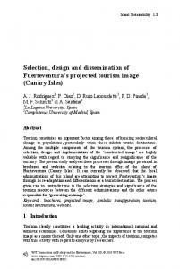
The earthworm has two sets of muscles. Under its skin is a thin layer of circular muscles running around the worm’s body. The circular muscles contract, making the earthworm longer and thinner. When the longitudinal muscles contract the worm becomes shorter and fatter [7], fig. 3. We can simplify this deformation of earthworm’s body by a 3D wire Frame model as an abstract formal pattern, fig. 4. This model is only consisted of red and green lines and black points. We modify its elements to find a model that mainly consists of blue lines and can change its form by minimum number of red lines. In this case, we use three structural modifications: add the diagonal lines (blue lines), subtract the extra lines (the green and red lines that don’t play an important role in deformation of model) and change the colour of points (change from black to blue), fig. 5.
Figure 3:
Figure 4:
A. longitudinal muscles, B. circular muscles [8].
In this shape rule, the longitudinal lines are as longitudinal muscles and the circles are as circular muscles.
WIT Transactions on Ecology and the Environment, Vol 114, © 2008 WIT Press www.witpress.com, ISSN 1743-3541 (on-line)
152 Design and Nature IV
Figure 5:
Modification sequence for the earthworm.
Figure 6:
An actual test of the result with the real models [4].
Figure 7:
Changing the result with the inverse direction rule.
The concept of a deployable structure is defined in the last step of this sequence that can be tested by a real model with elastic elements as main component, fig.6. It must be said that the blue lines with the same direction in each cylindrical model belong to one component. The result of modification sequence will be changed if we use the rule with inverse direction, fig. 7. The result of this part is the concept of a cylindrical deployable structure that can be used for different applications in architecture. In fact, we have a scissor concept in this structure but the originality of it is due to the use of elastic components in a cylindrical form; therefore the complicated joints are not WIT Transactions on Ecology and the Environment, Vol 114, © 2008 WIT Press www.witpress.com, ISSN 1743-3541 (on-line)
Design and Nature IV
Figure 8:
Figure 9:
Figure 10:
153
Manipulation of the form parameters.
An actual test of the result with the real models [4].
A. The cylindrical structure can be changed into a dome. B. The cylindrical structure can be changed into a spare.
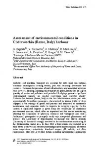
required. With the spiral deformation of elastic rods and simple rotatable joints this cylindrical structure can change its height and width. We develop this concept in the next section. The first modification is through manipulation of form or structure parameters. One of the possibilities of formal manipulation is the sequential increase of distance between connecting points, fig. 8, 9. The other possibility of structural manipulation is to add the new black and red lines and to exchange some blue points with red points, fig. 10, and fig. 11.
WIT Transactions on Ecology and the Environment, Vol 114, © 2008 WIT Press www.witpress.com, ISSN 1743-3541 (on-line)
154 Design and Nature IV
Figure 11:
Figure 12:
An actual test of the result with the real models [4].
Development through the array and actual test of the result [4].
One of the most common formal characteristics of the deployable structures is repetition of one part and spatial combination of these repetitive parts. We use array of one pattern for creation of a new concept with this characteristic, fig. 12.
4
Application in architecture
The concepts of deployable structures that are represented here directly or indirectly are on the basis of deformation principle of earthworm. Their WIT Transactions on Ecology and the Environment, Vol 114, © 2008 WIT Press www.witpress.com, ISSN 1743-3541 (on-line)
Design and Nature IV
Figure 13:
155
Different applications for deployable structures on the basis of the earthworm principle: A, B, C: Portable constructions with proper opportunity for transportation D: Portable constructions that can create different variants of space with the same elements and the same size [4].
WIT Transactions on Ecology and the Environment, Vol 114, © 2008 WIT Press www.witpress.com, ISSN 1743-3541 (on-line)
156 Design and Nature IV components with changeable length are inspired by the longitudinal and circular muscles of earthworm. These components play the main role for changing the curvature of elastic components and therefore changing the form of structure. This type of deployable structures can be used in interior, exterior and portable convertible constructions in architecture. However these structures might not be appropriate for certain applications such as large roofs or big building components. These structures can provide proper opportunities for portable architecture. They can create different variants of space with the same elements and the same size. These structures can be opened and closed and are spacesaving in closed form which is convenient for transportation, fig. 13.
References [1] Nachtigal, W., Bionik- Grundlagen und Beispiele für Ingenieure und Naturwissenschaftler, 2. Auflage, Springer, Berlin, 2002 [2] Otto, F., Wandelbare Dächer (IL5), Inst. Für Leichte Flächentragwerke (IL), IL mit Karl Krämer Verlag Stuttgart, P. 12; PP. 44–46, 1972 [3] Park, D. U., Materialgerechte lösbare Verbindungen bei glasfaserverstärkten Kunststoffen, 2. Forschungs Forum, FOMEKK/ ITKE/ DLR, Tagungsband, P. 8–10, 2004 [4] Matini, M.R., Biegsame Konstruktionen in der Architektur auf der Basis bionischer Prinzipien, Institut für Tragkonstruktionen und Konstruktives Entwerfen (ITKE); University of Stuttgart, Stuttgart, P. 98, 101, 102, 107; PP. 43–55, 72–75, 128–132, 2007 [5] Mitchell, W. J.: The logic of architecture – Design, computation, and cognition, MIT Press, London, 1990 [6] Knight, T.W.: Transformations in design – A formal approach to stylistic change and innovation in the visual arts, Cambridge University Press, New York, 1994 [7] Meinhardt, U., Alles über Regenwürmer, Franckh, Stuttgart, 1986 [8] Hess, W.N., Nervous system of the earthworm, lumbricus terrestris L., Journal of Morphology, Volume 40, Issue 2, P. 235–259, 1925
WIT Transactions on Ecology and the Environment, Vol 114, © 2008 WIT Press www.witpress.com, ISSN 1743-3541 (on-line)