Domain-specific base models are reused and customized to .... main idea of our reuse approach, and we describe the advantages of reusing base mod- ... The domain-specific base models allow writing powerful software generators which ..... One disadvantage of our method is that it takes significant time to implement new.
Application of a Generator-Based Software Development Method Supporting Model Reuse Joachim Altmeyer, Jan Peter Riegel, Bernd Schuermann, Martin Schuetze, Gerhard Zimmermann Computer Science Department University of Kaiserslautern, Germany Abstract: Two important phases in the software development process of large systems are modeling and coding of the system components and their interrelations. While the modeling phase is the creative part and must be done manually, the coding phase should be automated. In this paper we describe a generator-based software development method for large systems and an experimental implementation of this method. Domain-specific base models are reused and customized to application models for many projects within the domain. The application models are then input to specialized, powerful code generators which produce most of the application’s source code automatically. Furthermore, we discuss the reuse potential of using and customizing common base models and using domain- and component-specific code generators.
1. Introduction Reuse requires the existence of well-structured and well-defined software pieces which can be identified and instantiated in new designs. This process can take place in different ways. The basic level is to reuse written code directly (‘cut & paste’). Further structuring of the reusable code portions leads to libraries. Along with the object-oriented programming we find toolkits and frameworks [GHJ95], collections of (possibly abstract) classes for one or many aspects, which may be subclassed and instantiated in new designs. While these reuse strategies focus on code reuse, the pattern approach [GHJ95, Pre95] tries to support reuse of designs by identifying generic structures, socalled ‘reusable microarchitectures’ [GHJ93], in the software which can be applied to other software products. Design for reusability is an important aspect of all software engineering approaches: well-defined, well-structured, and well-documented components enable reuse of the component code. [JCJ92] describes components as the primary entities of reuse. [Pre95] identifies so-called hot spots in designs which encapsulate regions where necessary adaptations for potential reuse candidates must be performed. Our approach consists of a domain-specific software development method. Within this method we model major parts of the applications which make up a system with application-specific models. Many kinds of models we use are well known (e.g. object diagrams [Boo91]), but since we restrict ourselves to certain application domains, we are able to define stricter semantics for these models. The scope of our approach is the development of large systems of interacting software applications. When we talk about a system, we mean a set of applications which are veritable software products on their own, working together in a single application domain. These applications consist of different components implementing different aspects of the functionality the application is expected to realize. One component could be a graphics subsystem dealing with the user interface aspect. Or it could be an abstract data type managing the storage of application data.
Component models which are valid for many applications of the system are treated as common models and will be customized and reused for different application projects, making these models our primary reuse candidates. In contrast to other component reuse approaches described by [JCJ92], we do not use the whole component (or framework) as a high-level-language primitive. We support a kind of white-box components where the primary reuse takes place at the modeling level instead of the coding level, reusing suitable model portions. The necessary modifications to the component code are performed by generators, the second kind of reuse within our approach, which use the interrelations between the component models. In the case that the models change, the generators ensure overall global consistency of the application code simply by regenerating all components. We do not generate all of the application’s code, but only those components for which we can find powerful, but comprehensive, domain-specific models. While the main idea behind our method is not bound to any particular domain, every instantiation of it, i.e. every set of notations, models, and generators, is usually bound to and optimized for a certain application domain. So far, we are using a prototype tool (MOOSE) for our method in three different domains: for the development of a large ECAD system (‘PLAYOUT’) [ASS95, SSA95], we model and extend MOOSE itself with MOOSE (‘MOOSE’), and we develop software for building control and building simulation (‘BUILDING’) [RSZ97]. Our development method and the reuse approach are described in sections 2 and 3 while the implementation of our method is described in section 4. Related generatorbased approaches are addressed in section 5.
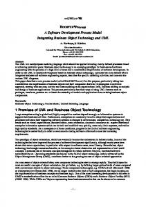
2. A Domain-Specific Software Development Method Model Types Large systems are, due to their complexity, usually not developed as one single application. They often consist of many applications which interact in a certain, welldefined way. Because all of these applications are developed for one domain, they all share a set of models typical for that domain. Such a common model shared by different applications is a base model. We define model and base model in the following way: Definition ‘Component Model’ A component model (e.g. a finite state machine model or an entity relationship model) is defined in a given notation and describes one aspect (statical, behavioral, etc.) of a system or an application. Definition ‘Base Model’ A base model includes the general parts of all component models which are shared by different applications. It serves as a common model for all application projects within one domain. The relations between the common and the application-specific models are shown in figure 1. The base model is application independent. It describes the whole domain and is therefore usually not very well suited for the direct design of different applications. For instance, behavioral aspects have to be refined for a given application, or object relations need to be changed to fit it’s needs. These changes are performed in a deriva-
glue component model base model characteristics 1
characteristics 2
derivation
derivation
+
+ application model 2
application model 1 similarities
Fig. 1
Base model and derived application models
tion step. The base model ideally has to be defined only once for all applications of a given domain, and it is created as a result of the domain analysis; however, our experiences show that minor changes will always be necessary. These changes can easily be propagated to the application code by generators. It is important to notice that the different component models are interrelated. We call these interrelations the glue: Definition ‘Glue’ The glue models the interrelations between component models. These interrelations may be given by model aggregation, by relations, by inheritance, or by notations like design patterns and other domain-specific notations. The purpose of the glue is to document what interactions exist between (or inside) components. For example, the user interface component uses access methods of the data management component to visualize results. The calls to these methods are generated from the glue between the components. The application-specific models contain parts of the base model as well as all local changes and additions to the base model defined in the characteristics. The changes and additions are necessary to achieve an optimized component functionality. Because the application-specific models are derived from the base model, different applications have many similarities. If the transformation steps are performed in a well-defined, formal way, it is possible to exploit the similarities, for example to support an (semi-) automatic data exchange between different applications, generated from their data models [SSA95] (see also section 4). Characteristics and application models are defined as follows: Definition ‘Application Model’ An application model includes all component models of one single application. It consists of model parts derived from the corresponding base model (the base model may be modified in the derivation step) as well as additional parts necessary only for one application which are not part of the base model. Typically, the component models within an application model are highly interrelated (→glue).
Definition ‘Characteristics’ Characteristics contain all changes of the base model which are necessary to achieve an individually tailored application model for one application. For example, object types are deleted from or added to the base model, or a completely new component model (e.g., a library for a certain purpose) is added in order to get the model for one application. A Model-Based Software Generation Approach Figure 2 shows the data flow of our software development method, linked to the ‘traditional’ phases of software development: analysis, design, and implementation. This is not a process model: the overall development process, which is not discussed here, requires some of the steps and phases to be performed repeatedly. problem description
software requirements analysis
software design design
code
implementation
domain analysis domain description appl. domain
base model manual characteristics
application description appl. project
Fig. 2
primitives architecture model model transformation
component code
application model
manual
generation
Data flow for the model-based software generation
Figure 2 looks pretty domain independent; nevertheless, every instantiation of the method is domain-dependent: the notations are influenced by the domain, e.g. for ‘BUILDING’ we extended the entity relationship modeling with relation types defining topology or materials. The base model depends completely on the application domain. And the generators interpret the models in a domain-specific way and are optimized for one domain. Before we may start with the development of individual applications, we have to set up the base model for the domain as shown in the large grey box in figure 2. This domain analysis phase is not discussed in this paper. So far, we did not use any standard analysis methods, but we followed our own procedures. In principle, any method suitable for the application domain can be used, but it must be ensured that it also yields domain-specific notations and semantics for the models, or these must be found in a separate process. The base model is then gained manually from domain knowledge, which is a creative step. To assure a broad applicability, the base model should be defined to be independent of application-specific details. Adding the application-specific details is performed in the design phase of each application project. Afterwards, we may start to analyze the application’s problem description. Starting point is the base model. The application’s requirements are specified as ‘deltas’ between the base model and the application’s needs. These ‘deltas’, the characteristics,
are manually derived from the problem description. They describe which parts of the base model need to be changed or extended. Typical contents of the characteristics are: addition or deletion of base model elements, addition or deletion of relations between base model elements, addition of models, and implementation hints. The creation of the characteristics is a very important step because it reuses the information of the base model while defining necessary changes. During the design phase, a model transformation step takes the base model and the characteristics as input and creates the application model. This application model will fit the needs of the application with respect to the modeled elements, performance requirements, possibly non-functional requirements, and so on. It now contains all information needed for the generation of the components of the application under development. In the subsequent implementation phase, the implementation code of the application’s component is generated from the application model (see for example [ASS95]). This generation step requires code primitives corresponding to the elements of the model notation and the architecture model of the component as additional input. Because we restrict our approach to one domain at a time, we can select very powerful, domainoptimized primitives, for example response time optimized primitives for the domain of real-time control systems. The result is component code for the application which is, in contrast to traditional frameworks, trimmed to exactly meet the application’s needs. Cross-Component Modeling Many components of an application cannot be considered independently of each other. For example, a graphical user interface is strongly coupled with the data management component. Within our approach we make these interrelations, the glue, explicit by defining them at the modeling level. This results in a clear understanding of the dependencies between different models, but more important, we can exploit this information in the generation phase: we can, for example, instantiate exactly those parts of a model which are referred by another model. The most powerful use of these interrelations is achieved by specialized generators (see following section) which consider more than one model at a time including the glue between the models and produce thereby very efficient and well customized implementations.
3. The Reuse Approach Section 2 described our software development method; in this section we present the main idea of our reuse approach, and we describe the advantages of reusing base models. We characterize different generators considering their foci, and we emphasize the profit exploiting the application model by using powerful generators. Reuse Strategies Within our approach, it is the main goal to find generic, domain-specific structures and to describe these structures with a domain-specific base model. The component models within this base model can be reused for different application projects. The reuse of these well-established components is known as compositional reuse [Pri93]. The overall advantage of this compositional reuse at modeling level is that all fundamental
operations of the reuse efforts described in [BiR89], i.e. finding, understanding, modifying, and composing components, are addressed at an abstract level. This allows an easier handling of these tasks than at coding level. [BiR89] describes the advantages of a reuse of design versus a reuse of code in detail. To support an adequate reuse at modeling level, management of the different domainspecific models is necessary. Within our software prototype system MOOSE [ASS95] (see also section 4), this task is supported by a configuration and version management. The code generation using characteristics of the application model distinguishes our approach from systems like Idea which find designs within a model library using a given software specification [Lub91]. Considering our modeling and reuse method, we notice that our approach develops it’s abilities to the full if the target system is not only large and complex, but if it also consist of different partitions which can profit from customizing common models. Besides this reuse of common models we perform a generative reuse [Pri93]. Here, the generic (reused) information is encoded within our software generators (e.g. as code templates). Using structures at modeling level and the additional information of the application characteristics, software generators implement the given application model as customized application code. The domain-specific base models allow writing powerful software generators which are tuned to these domain-specific tasks. The use of software generators in addition to the application models based on the common models and the characteristics allows a powerful customization within the final implementation step. Therefore, our generative reuse based on common models guarantees a high reuse potential with a large flexibility. Specialization of Generators We distinguish two extreme types of generators: universal generators and component generators. Universal generators are widely independent of domains and of domainspecific tasks, respectively. Examples of universal generators are C++-code generators as they are delivered with many commercial CASE tools. On the other hand, component generators support specific components and depend on specific requirements. Examples are code generators delivered with specialized systems like Statemate and SDT. Because specific requirements appear in specific domains and requirements may be shared by different domains (e.g. real-time is demanded in the domain of embedded systems and in some simulation domains), component generators and their models are not necessarily restricted to one domain. Due to this specialization the code created by component generators is more powerful than the code created by universal generators. However, the border between universal generators and component generators is flowing. Benefits of Cross-Components Generators The focus of a component generator may be local to one component model or it may stretch over the entire application model. We call component generators which do not look deeper into the remaining parts of the application model single-component generators.
If the focus of the generator is the entire application model, the generator makes use of the glue and of modeling structures within the remaining component models. We call generators which look at the entire application model cross-component generators. Modeling structures are - in terms of a graph-based representation - generic subgraphs which can be identified within the model. Examples are relation types, e.g the aggregation relation (part-of, consist-of, etc.) or design patterns [GHJ95, Pre95]. These modeling structures are interpreted and translated by the software generator into suitable implementation structures considering the task of the component to be implemented (see figure 3). application model
C
component model
C
modeling level coding level application code
C
a) single-component generator
Fig. 3
component code C
b) cross-component generator
generator focus
Single-component generator versus cross-component generator
In section 4 examples of single- and cross-component generators are presented in more detail. The main advantage of cross-component generators over single-component generators is the automatic consideration of modeling structures within several parts of the application model (see for example [QAS94]). Without these generators the programmer has to consider these structures at implementation level.
4. Implementation of the Method The concepts from the previous sections are implemented within the experimental software engineering environment MOOSE (Model-based Object-Oriented Software Generation Environment). MOOSE acts as an engineering framework for the different model editors and code generators. The framework in itself is domain independent, while every set of editors and generators may very well depend on a specific application domain. In this section, we give a short overview about the MOOSE framework, and we examine three of its generators in more detail. MOOSE Framework The overall structure of MOOSE is depicted in figure 4. We provide one (in most cases graphical) editor for every supported type of component model. At the moment, these are editors for extended entity relationship diagrams (EER, comparable to object type
other models e.g. pattern models
model of the user interface
model of the graphics
characteristic of the application
model of the data management Cell
Net Pin
editors internal database
MOOSE file communication generator
remote access generator C++-code generator
PSIGene: simulator generator hypertext VisualdocuWorks mentation generator generator
class x method y ...
MOOSE Fig. 4
(pin < ( key 1) ( name in) > dcoInternParts(this); this->conInternObjectType (__Engine); if (__Engine) __Engine->conInternParts(this); }
Generated C++ code Beside these declarations, the C++ generator also creates the implementation code.
Figure 6 shows a short code fragment that gives an impression of a generated class description. At this point, it is important to notice that not only the declarations but also the whole implementation code of the methods are generated. This is one of the most important differences between our C++ code generator which is optimized for internal data structures of applications and general purpose code generators as they are delivered with many CASE tools. More detailed descriptions of MOOSE and the C++ generator can be found in [ASS95]. Remote Access Generator The remote access generator is a good example for a domain-specific cross-component generator. It is used in conjunction with the C++ generator and adds remote access capabilities to a database via a local network. It is domain-specific in the sense that it
was created to support the development of large CAx frameworks (e.g. CAD, CASE). In this domain, we often find a number of tools grouped around a central design database or repository. The database acts as an archive workspace for all design data, while the tools reside on top of a private workspace holding exactly that amount of data needed by the tool at a given time. Thus, the private workspace acts as a kind of cache for the design data. The remote access generator creates methods for the management of this cache, e.g. functions to dynamically reload portions of the design data. Tool and database models are derived from a common base model. Therefore, the data models of the tools are usually very similar to, but never identical with the data model of the design database, and a mapping between the models is necessary. The generator is a cross-component generator in the way that it interprets the EER models of two applications (tool and database), as well as a declarative mapping table, and creates all necessary code to map the data on-the-fly while loading the private workspace. More details about this generator can be found in [SSA95]. PSiGene PSiGene (Pattern Based Simulator Generator) is also a highly domain-specific crosscomponent generator. The application domain is real-time building simulation [RSZ97]. The aim was to create a generator which is able to produce a large family of highly specialized building simulators which are always optimized for one purpose. For this restricted domain and for a limited number of physical effects (which we provide as code templates) we reach 100% code generation. This is only possible because the generator considers the dynamic as well as the static aspects of building simulation in a cross-component fashion. It combines the simulation objects class model with the model of several libraries, for example, standard simulation functions, a real-time simulation kernel, user interface libraries, finite state machine models, and a model of the building. The glue between these models is provided by simulation patterns, which are influenced by (but not identical to!) design patterns as described in [GHJ95, Pre95]. These patterns define how the different models are interrelated, and they contain code fragments (for object interaction and for simulation functions) from which the ‘glue’code is generated. Within PSiGene, the different types of patterns are implemented as VisualWorks classes. They are the objects that form the generator, and they are capable of generating code for their different instantiations. Every type of pattern may be seen as a partial generator for one specific purpose. The generated code can be optimized and linked in several different ways, the optimization is performed by the generator methods implemented within each pattern. PSiGene is tightly coupled with the VisualWorks ADT generator (see figure 4). It uses the classes and access methods created by the VisualWorks generator. PSiGene is very flexible: new patterns can easily be added which accommodate new model types, e.g. differential equations for the simulation of continuous effects.
5. Related Work The main idea behind our reuse approach has already been outlined in section 3. Reuse of design is also a major concern of the DSSA initiative (Domain Specific Software Architecture project by DARPA, see [DSS95]). DSSA’s focus is on the definition of a reference software architecture which can be used for many applications of a given
domain, and on the reuse of components (megaprogramming) within this architecture. In contrast to that, our focus is on the adaptation of successful base models and on the reuse of design artifacts by generating customized components. However, many ideas and techniques like the restriction to some well-supported domains and the use of code generators are the same. Our approach shares with application generators (e.g. UI builders, simulation systems) that it is always optimized for one domain. However, we rely on object-oriented modeling and the cross-component approach, and we believe that our method in itself is usable in many domains, only concrete manifestations of the method are domain dependent. The code generation by generators like PSiGene is a one-step approach. There is another approach to code generation, based on program transformation (see for example GenVoca [BST94] or CIP [GoH85]). There, an abstract program is transformed to implemented code by a sequence of refinement steps. The input for these types of generators is usually more abstract than our models. However, the goals of this approach (in terms of productivity gains, reuse potential, scalability, and optimizations) are the same. Although GenVoca has a different focus, we share its basic principles (see [BST94]): generation from subsystem building blocks, standardized interfaces, and parameterization. One might argue that the same results could be obtained with libraries or application frameworks. But both approaches tend to be relatively inflexible, of large size, and complex. Our approach ensures that a kind of ‘customized application framework’ is generated individually for each application, implementing exactly the needed functionality without additional overhead or unneeded complexity.
6. Conclusions In this paper we introduced our method to model and generate components of large software systems and to reuse domain-specific common models. The method is supported by a prototype implementation, MOOSE, which is primarily a framework for different domain-specific notations, models, and generators. Up to now, it is not possible to generate 100% of code for all applications, but the integration of handwritten code is easy. Our method is compatible with traditional OOA/OOD methods and can be combined with these wherever it is not possible or feasible to use generators. Our reuse approach is an alternative to traditional reuse forms where completely developed components are integrated into new designs. The main difference is that the reuse candidates (model parts) are identified and instantiated at the modeling (i.e. design) level rather than at the coding level, and that all work necessary to integrate the customized component code into the application is done automatically by generators. One disadvantage of our method is that it takes significant time to implement new model editors and generators. In contrast to that, the creation of these seems to be relatively straight forward taking our experience with the existing tools into account. And the disadvantage of spending time for the development of the tools is, based on our experience, by far outweighed by the productivity gains, reduced error rates, and increased consistency delivered by our method. Furthermore, our method still lacks a properly defined development process, and up to now we did not define a general
domain analysis method. In the future, we will try to deal with these problems, as well as we will emphasize the component aspect of our method. The experiences we collected during the implementation of large systems, like MOOSE itself, a large ECAD system, and a building automation project are very promising. Productivity increases significantly, tedious implementations of component code are left up to the generators, and, in addition to the generator input, the models serve as the primary entity for reuse and as a comprehensive documentation of the implemented components. References [ASS95]
[BiP89] [BiR89] [Boo91] [BST94] [DSS95] [GHJ93] [GHJ95] [GoH85] [GOP90] [JCJ92] [Lub91]
[Pre95] [Pri93] [QAS94]
[RSZ97]
[SSA95]
J. Altmeyer, B. Schürmann, M. Schütze, “Generating ECAD Framework Code from Abstract Models”, Proceedings of the Design Automation Conference ’95, San Francisco, California, 1995 T.J. Biggerstaff, A.J. Perlis, “Software Reusability; Volume I; Concepts and Models“, ACM Press, Addison-Wesley, New York, 1989 T.J. Biggerstaff, C. Richter, “Reusability Framework, Assessment, and Directions“, in [BiP89] G. Booch, “Object-Oriented Design with Applications“, The Benjamin/Cummings Publishing Company, 1991 D. Batory, V. Singhal, J. Thomas, S. Dasari, B. Geraci, M. Sirkin: „The GenVoca Model of Software-System Generators“, IEEE Software, September 94, 1994 Online-Document, “What is DSSA?”, http://www.lfs-owego.com/dssa/what-isdssa.html, August 1995 E. Gamma, R. Helm, R. Johnson, J. Vlissides: “Design Patterns: Abstractions and Reuse of Object-Oriented Design“, Proc. ECOOP ‘93, 1993 E. Gamma, R. Helm, R. Johnson, J. Vlissides, “Design Patterns“, Addison-Wesley, 1995 G. Goos, J. Hartmanis, eds.: “The Munich Project CIP“, Vol. I, Springer Verlag, 1985 K. E. Gorlen, S. M. Orlow, P. S. Plexico, “Data Abstraction and Object-Oriented Programming in C++”, John Wiley & Sons, 1990 I. Jacobson, M. Christerson, P. Jonsson, G. Övergaard, “Object-Oriented Software Engineering“, ACM Press, Addison-Wesley, 1992 M. Lubars, “Domain Analysis and Domain Engineering in Idea“, in “Domain Analysis and Software Systems Modeling”, R. Prieto-Diaz, G. Arango (eds.), IEEE CS Press, Los Alamitos, California, 1991 Wolfgang Pree, “Design Patterns for Object-Oriented Software Development“, ACM Press, Addison-Wesley, 1995 R. Prieto-Diaz, “Status Report: Software Reusability”, IEEE Software, May 1993 S. Queins, J. Altmeyer, B. Schürmann, “Model-Based Reuse of Object-Oriented Graphic Components for CAD Systems”, Proceedings of the 39th International Scientific Colloquium, Ilmenau, Germany, 1994 J.P. Riegel, M. Schütze, G. Zimmermann, “Pattern-Based Generation of Customized, Flexible Building Simulators”, CAAD Futures 97, Munich, Germany, 1997, to be published M. Schütze, B. Schürmann, J. Altmeyer, “Generating Abstract Datatypes with Remote Access Capabilities”, in “Electronic Design Automation Frameworks; Volume 4“ , F. J. Rammig, F. R. Wagner (eds.), Chapman & Hall, 1995