International Journal of
Intelligent Systems and Applications in Engineering ISSN:2147-67992147-6799
Advanced Technology and Science
www.atscience.org/IJISAE
Original Research Paper
Application of Angle-Modulated Particle Swarm Optimization Technique in Power System Controlled Separation WAP Almoataz Youssef Abdelaziz1*, Walid El-Khattam, Mohammed Received 29th December 2013, Accepted 28th January 2014 DOI: 10.1039/b000000x Abstract: One of the recommended preventive plans against the wide area disturbances is WAP, Wide Area Protection, through controlled system splitting or separation. In this paper, authors are proposing three simple algorithms that are intended to be operating online, analyze data from wide-area PMUs placed in different parts of the grid, process the system state and lines’ status and issue disconnecting actions to certain lines in the grid to form islands with minimum imbalances of power between generation and loads. First a simple approach is introduced which performs an extensive search for proper splitting strategies. The authors then present modified approaches which could make the whole system act within much shorter times. All the presented algorithms are analyzed and comments are made on ways to enhance their performances. This will emphasize on how such WAP systems would be designed and developed and if necessary tailored to fit specific systems or applications. Keywords: Controlled Separation, Particle Swarm Optimization, System Splitting, Wide Area Protection.
1. Nomenclature AMPSO: Angle-Modulated Particle Swarm Optimization PMU: Phasor Measurement Unit PSO: Particle Swarm Optimization WAP: Wide Area Protection
2. Introduction Power systems today are made up of thousands and thousands of different components. They are widely and, in some cases, massively spread over vast lands and territories. Hence reliability and security of their operation is no longer an easy target. Challenges in maintaining healthy operation are magnified and elevated by the power system size. Despite huge advancements in different power system components, operations, and protection technologies, today’s power systems are more vulnerable to blackouts than ever before. One of the recommended preventive plans against the wide area disturbances and the blackouts is Wide Area Protection. With the rapidly growing capabilities in computer and communication technologies, opportunities are now being available for the introduction of advanced wide-area protection and control systems which shows a great potential. Such systems would receive wide-span information, e.g. systemwide voltages, angles, active and reactive power flows, etc., and analyze them, indicating whether the system is on the urge of a transformation into an unstable state, and thus, issuing wide-span, coordinated actions that will save the system from proceeding to total collapse, or even, mitigate the wide-area disturbance effects upon the system. System splitting, also known as controlled separation, is to split the interconnected transmission network, deliberately and on _______________________________________________________________________________________________________________________________________________________________
1
Ain Shams University, Faculty of Engineering, Electrical Power & Machines Department, Egypt * Corresponding Author: Email:
[email protected]
This journal is © Advanced Technology & Science 2013
purpose, into islands of load with matching generation at proper splitting points by opening a selection of transmission lines and ties. After which, load shedding and sometimes generation rejection should follow in order for the load and generation to remain balanced within balance, keeping the majority of the system intact and hence avoid cascading instabilities or even partial or total blackouts. The study of previous blackouts and outages suggest that if proper system splitting strategies along with suitable load shedding and minimized generator rejection had been performed within short time, some blackouts could have been avoided and mitigated. In this Paper the authors are proposing three simple real-time algorithm that are intended to be operating online, analyze data from wide-area PMUs placed in different parts of the grid, process the system state and lines’ status and issue disconnecting actions to certain lines in the grid to form islands with minimum imbalances of power between generation and loads, without violating thermal and overloading constraints of the ties left intact within each island. Performances of the three different algorithms and techniques, utilized for finding suitable solutions for the controlled separation problem, are explored and compared. A conclusion is drawn in light of this comparison and suggested ideas for further future work are presented.
3. The Controlled Separation Problem System splitting, also known as controlled separation, is to split the interconnected transmission network, deliberately and on purpose, into islands of load with matching generation at proper splitting points by opening a selection of transmission lines and ties. After which, load shedding and sometimes generation rejection should follow in order for the load and generation to remain balanced within balance, keeping the majority of the system intact and hence avoid cascading instabilities or even partial or total blackouts. The study of previous blackouts and IJISAE, 2014, 2(3), 51–57 | 51
outages suggest that if proper system splitting strategies along with suitable load shedding and minimized generator rejection had been performed within short time, some blackouts could have been avoided and mitigated [1-3]. Operating states of the power system have been defined before as [4]: • Normal State. • Alert State. • Emergency State. • In-Extremis. • Restoration.
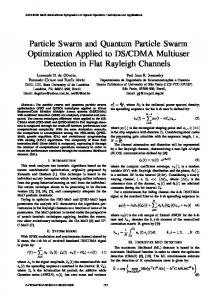
Fig. 1.
Power System Operating states [4]
The system should be designed to act in the emergency state and help stop and save the situation from devastating. A practical controlled separation scheme needs to address the following three critical problems [5]: • Where to separate? (i.e. separation points to form stable islands) • When to separate? (i.e. separation timing) • What to do after separation? (i.e. post islanding actions like load shedding and/or generator rejection) When to act exactly or what triggers the system should be a threatening instability or signs derived from the input data received by the system, but it is not in this paper’s scope. However, a lot of research is going on and shall be put into this “prediction of instabilities” scope. So is the case with the postseparation actions. The main concern in this paper with how to act and the separation techniques. Following the decision that separation is needed, the following describes the set of problems and/or constraints that the controlled separation has to take into consideration in order to derive proper and relatively stable islands. The most important thing is that those islands are proven to be stable and persistent after the separation in order to maintain most of the system’s integrity, minimize the loads that experienced outages and ease the restoration process. Hence the solution that is found suitable should satisfy a set of constraints, formulated and discussed in numerous previous references [1], [6]: 3.1. Separation and synchronization constraint Asynchronous groups of generators must be separated into different islands and generators in each island must be synchronous with each other. Following a serious contingency, some generators tend to swing together, while others tend to swing against those. Uncontrolled islanding will be inevitable, due to protection systems operating against and to prevent out-ofstep oscillations [7, 8]. A suggested solution would be to determine the different groups of generators that swing together and start forming separate islands containing those coherent generators and disconnected from the other asynchronous groups’ islands. Bottom-line: The first constraint would be identified as 52 | IJISAE, 2014, 2(3), 51–57
that buses of synchronized generators shall be connected in the same island and separate from the other generators that are swinging against them. Several previous researches [9], [10] have discussed this issue and in this paper. Here, it is assumed that the coherent generator groups are previously identified and set. 3.2. Power balance constraint In order to ensure that the resulted islands remain intact and stable, each of the islands should have, theoretically, equal generated active power and load power consumption. Of course, this is impossible as some areas would have concentrated generation and others would have a majority of loads. Therefore, the constraint is revised to allow a small pre-set imbalance between generation and load of active power, or in other words power generation shall be roughly equal to power load. The imbalance will not be allowed to evolve into a major instability by further measures, either load shedding in case of load surplus or generator rejection in case of surplus in generation. Reactive power is not considered as constraint, as it assumed that the local measures are enough to solve this issue, i.e. capacitor banks, Static Var Compensators will compensate for additional reactive power demand and under-voltage load shedding would save the island from collapsing due to deficiency in reactive power supplies. 3.3. Rated Value & limit constraints If the main aim is to maintain most of the system’s integrity through maintaining the integrity and stability of the sub-islanded grids, then the transmission lines must not be loaded over their thermal and steady-state capacity limits. The grid degrades through cascading disconnections of the ties carrying its power flows, by protection systems, due to overloads and short circuits. To prevent that, it has to be ensured that overloading, if it occurs, is within the thermal limit for each tie.
4. Direct Searching Method The following flowchart, in Fig. 2, shows simply the stages of the algorithm. The main and major benefit of this algorithm is its absolute simplicity, it could be implemented on any type of system and achieve results. However its performance is relatively more time consuming. 1. Initialization: At first, the algorithm initializes the system parameters, i.e. the number of buses, number of lines, connectivity matrix that contains the lines and ties between all buses in the grid, groups of coherent generators, the injected powers of all buses meaning the difference between the generated and consumed powers, the allowed margin of power imbalance in each island, thermal limits and thermal overloading coefficients of all lines, impedances of branches. 2. Calculating the number of possible grid configurations: The number of possible candidate solutions that the algorithm is intended to test and study equals to 2 to the power of number of the lines in the grid.
m 2 number_ of _ lines
(1)
Where m = number of possible configurations of the grid. 3. Ensuring that no bus is left unconnected: It should be noted that all load buses are included and connected to an island. This mitigates the blackout minimizing the amount of load loss over the whole grid. 4. Ensuring that no incoherent generator buses are connected: This journal is © Advanced Technology & Science 2013
This ceases the instabilities, resulting from the incoherent generators swinging against each other, from developing. 5. Ensuring that all coherent generator buses are connected to each other: This will minimize the loss of generation and loss of supply to load by keeping most of the integrity of the generator buses. 6. Conduct Power imbalance calculation: For each island the difference between the power generation and power load is calculated to make sure it is within the preset limit. 7. Conduct Approximate DC power load flow: To make sure all lines left intact within each island will not be severely overloaded and hence result in further disconnection and degradation of the grid. 8. Add possible solution: If candidate solution is verified to satisfy all the prior constraints then it will be added to the set of possible separation solutions. The algorithm was engineered and programmed on Matlab and using a 1.73GHz dual core processor with installed 2 GB of RAM and running a 32-bit Windows 7 Operating system. So far, the algorithm was tested on 5, 9 and 14 bus standard systems. Here, only running the algorithm on the IEEE 14-bus standard test network is previewed. The following Table I shows the parameters, results and times: Table I - Parameters, Results and Times for IEEE 14-bus system (total online solution) Number of lines Number of candidate configurations Time to explore all candidate configurations Time taken to find the first possible separation technique Number of possible separation techniques found
20 lines 2^20=1048576 7.5 minutes (450 seconds) 39.3 seconds 256
The results show that the program, yet simple, but will take extensive time to find the possible solution. This will not be appropriate to provide a suitable separation technique in short time to save the system. This will not be appropriate to provide a suitable separation technique in short time to save the system. Doing part of the job as offline work will be the solution. The algorithm was further developed so that the stages 2-6 can be performed offline and their results will be ready prior to any instability, the system will have a much less number of candidate solutions to explore. For the purpose of this simulation, generation power at bus-2 is increased to 200MW.
Fig. 2.
Direct Searching Controlled Separation Algorithm Flowchart
Table II shows the Parameters, Results and times for the algorithm running on the same IEEE 14-bus standard system, but after doing most of the job, that is doable, offline.
This journal is © Advanced Technology & Science 2013
IJISAE, 2014, 2(3), 51–57 | 53
Table II - Parameters, Results and Times for IEEE 14-bus system (partially online solution) Number of candidate configurations (that already satisfy steps 3-6) Time to explore all candidate configurations Time taken to find the first possible separation technique Number of possible separation techniques found
484 0.5304 seconds 0.2496 seconds 256
As shown the result of the system is exceptional and getting part of the algorithm processing to be done offline saved a lot of time for getting the final suitable separation solution. The time taken by the online processing is very suitable to be taken by a realtime application and will help save the system in appropriate short time.
5. Angle Modulated Particle Swarm Method Search spaces of controlled separation problems are huge. In these cases, population based searches are a very valid proposed solution. Particle Swarm Optimization (PSO) is a population based algorithm first introduced by Dr. Russel C. Eberhart and Dr. James Kennedy in 1995 [11]. As described by Eberhart and Kennedy, the PSO algorithm is an adaptive algorithm based on a social-psychological metaphor; a population of individuals (referred to as particles) adapts by returning stochastically toward previously successful regions [12]. Particle Swarm has two primary operators: Velocity update and Position update. During each generation each particle is accelerated toward the particles previous best position and the global best position. At each iteration, a new velocity value for each particle is calculated based on its current velocity, the distance from its previous best position, and the distance from the global best position. The new velocity value is then used to calculate the next position of the particle in the search space. This process is then iterated a set number of times or until a minimum error is achieved. The dimensionality of a problem influences the computational complexity in converging to a valid solution. Angle modulation is applied to reduce complexity of binary problems by generating a bit string to solve binary problems using PSO to evolve the function coefficients of a trigonometric model. Instead of evolving a high dimensional but vector, angle modulation reduces the problem to a four-dimensional problem defined in continuous space. Experimental results show that the angle modulation method is faster than the standard Binary PSO and that accuracy is improved for most benchmark functions used [13]. The Angle Modulated PSO (AMPSO) is a PSO algorithm that employs a trigonometric function as a bit string generator. The function is derived from a technique used in the field of signal processing from the telecommunications industry and is based on angle modulation. The standard PSO is then applied to optimize the simpler 4-dimensional tuple (a, b, c and d) instead of evolving the actual bit string. After the PSO iteration, the parameters are substituted back into equation. The resultant function is then sampled at the evenly spaced intervals to generate a bit for each interval, with the set of all generated bits representing the binary vector solution to the original problem. The benefit of the AMPSO is that a larger dimensional binary space can be represented by a smaller 4-dimensional continuous space. Results from the optimization are produced in a shorter period time, as only 4 parameters need to be optimized instead of the original ndimensions. Previous literature [14, 15] have explored relying on the same technique for some part of the solution, however 54 | IJISAE, 2014, 2(3), 51–57
because of the random nature of this optimization technique the generated solution may result in some isolated buses. Thus the former researchers added post-processing stages that added to the time and resulted in solutions that were not purely the result of the AMPSO. In this research, it is targeted to use only AMPSO and tried to decrease the time through some programming modifications. The algorithm here only explores solutions through solving only the power imbalance constraints. The algorithm for the AMPSO based controlled separation algorithm is as explained and shown: 5.1. Initialization: At first, the algorithm initializes the system parameters, i.e. the number of buses, number of lines, connectivity matrix that contains the lines and ties between all buses in the grid, groups of coherent generators, the injected powers of all buses meaning the difference between the generated and consumed powers, the allowed margin of power imbalance in each island, the coefficients of the trigonometric angle modulation function and fitness function. Processing: In every iteration, for each particle: i. Substitute current positions in the four dimensions into the trigonometric angle modulation function to get lines positions:
𝑔 𝑥 = sin 2𝜋 × 𝑥 − 𝑎 × 𝑏 × cos 2𝜋 × 𝑐 × 𝑥 − 𝑎
+𝑑
ii.
For each line, to get its status: If g(x)>0 then g(x)=1. If g(x) Vmax then vid = Vmax else if vid < -Vmax then vid = -Vmax 5.2. Output: Produce a record of all solutions and present top set of solutions This journal is © Advanced Technology & Science 2013
found during the iterations. The algorithm was engineered and programmed on Matlab and using an Intel Core i7 2.1 GHz processor with installed 4 GB of RAM and running a 62-bit Windows 7 Operating system. So far, the algorithm was tested on 5, 9, 14 and 30 buses standard systems. Here, only running the algorithm on the 9-bus standard test network is previewed. The following Table III shows a sample of the results and times achieved by this algorithm: Table III. Parameters, Results and Times for 9-bus system (total online solution) Number of lines Number of candidate configurations Time to complete all 15 iterations of 20 particles (300 steps) Time taken to find the best separation technique
9 lines 2^9=512 3.12 seconds 0.156 seconds
In comparison with previous literature, this algorithm has reached the best result during the second iteration, where every iteration is of 20 particles each. The best solution was found by the 16th particle in the second iteration. In previous literature [14, 15], the same best solution was claimed during the fifth iteration using the same population size; number of particles, which is 20. During a lot of simulations, results also showed that it reached the same best solution during the first iteration, by the 16th particle, however this was achieved by a population size of 30 particles. Despite that, it is not the best solution in respect to time taken as the time taken was 0.166 seconds. As shown, due to the random nature of the optimization problem, results may differ in each run. In this research, the same algorithm was run for the 14 bus and 30 bus IEEE systems but unfortunately did not perform successfully. Due to the random nature of the problem in binary space dimensions, this technique has only shown its big success in solving smaller grids. This still can be utilized if the bigger systems are clustered into smaller grids by compressing groups of buses or regions into one bus and considering the ties that only connect then to the other groups/regions as the only transmission lines studied.
6. New Online Method- “Sweeping and Keeping” The Bioinformatics Toolbox™ product extends the MATLAB® environment to provide an integrated software environment for genome and proteome analysis [16]. In this research a Bioinformatics toolbar function, called graphtraverse, is used to analyze the relationship between the buses and present it as a path for the second phase to operate on as a guide for processing. The algorithm only concentrates on solving the controlled separation problem by trying to satisfy the power imbalance constraint in the islands. Initializing the algorithm: In this preliminary step the algorithm initializes the system data by constructing the system connectivity matrix, in addition to forming the matrix that contains generators that are planned to be joined together in each same island. It will also realize how many islands are required by setting. Sweeping: The algorithm here uses a pre-programmed function to traverse through the grid starting from each island’s main generation bus. This function will travel through grid exploring and recording the buses that it traverses. It will use Breadth-First method which means that the order of buses will be according to closest from origin bus.
This journal is © Advanced Technology & Science 2013
Fig. 3. Angle Modulated Particle Swarm Optimization-based Controlled Separation Algorithm Flowchart
This will create trails, according to number of required separated islands, for each agent of the second part of the algorithm to follow and decide whether each studied bus will be part of the same island or of another. Keeping: According to the number of islands, there will be agents or parts of the program loop, each concerned with its respective island and will follow the trail got from the prior part of the program, the sweeping, and will compare this bus power to the imbalance IJISAE, 2014, 2(3), 51–57 | 55
of its island. If the bus power doesn’t violate the power imbalance constraint, if added to this island, then it is added and connected to the island. All its transmission lines that are affiliated with the first island will be set to “ON” and hence will not be disconnected by the system. All its transmission lines that are affiliated with other islands will be set to “OFF” and hence will be disconnected by the system and tripping signals will be ordered to transmit to the line’s involved circuit breakers. In case the bus power will violate the power imbalance constraint the algorithm will skip it for the mean time and will proceed with the next bus in the sequence. This bus will then be left to other agents, of the other islands, to consider and study and if there is a possibility it will add it. This part is looped until all buses are covered. If a bus or more remains unconnected then the algorithm will study which island could that bus be connected to, to explore all these options then decide the connection according to which island will be the best choice to minimize the imbalance. The program terminates after all buses have been decided to which islands each is connected. The algorithm was engineered and programmed on Matlab and using an Intel Core i7 2.1 GHz processor with installed 4 GB of RAM and running a 62-bit Windows 7 Operating system. So far, the algorithm was tested on 9 and 30 buses standard systems. 1) Running the algorithm on the 9-bus standard test network is previewed. The following Table IV shows a sample of the results and times achieved by this algorithm for solving the 9-bus system: Table IV - Parameters, Results and Times for 9-bus system (sweeping and keeping) Number of lines Number of candidate configurations Time taken to find the best separation technique
9 lines 2^9=512 0.0312 seconds
As shown, for solving the 9-bus system, it took the algorithm 0.0312 seconds! This time is off course much shorter than all the previous literature results [13, 14]. It is even shorter in duration than the results achieved by the prior two techniques explained and presented in this research. By far this is the fastest and most successful result, known to the researchers, for the 9-bus system. 2) Running the algorithm on the IEEE 14-bus standard test network is previewed. It has to be noted that the system was modified for the purpose of this simulation test, generation of bus 2 was increased to 200MW. The following Table V shows a sample of the results and times achieved by this algorithm for solving the IEEE 14-bus system:
Fig. 4. New Sweeping and Keeping Controlled Separation Algorithm Flowchart Table V - Parameters, Results and Times for 14-bus system (sweeping and keeping) Number of lines Number of candidate configurations Time taken to find the best separation technique
20 lines 2^20=1048576 0.0468 seconds
3) Running the algorithm on the IEEE 30-bus standard test network is previewed. The following Table VI shows a sample of the results and times achieved by this algorithm for solving the IEEE 30-bus system: Table VI Parameters, Results and Times for 30-bus system (sweeping and keeping) Number of lines Number of candidate configurations Time taken to find the best separation technique
41 lines 2^41=2.1990 x(10^12) 0.3276 seconds
As shown, for solving the 30-bus system, it took the algorithm 0.3276 seconds. Again, this time is much shorter than all the previous literature results [1], [5], [6], [14] and [15] which were 2.5 seconds and 1 minute, noting also that the first two references were studying other constraints like post-separation violation of overloading limits and the last two references were outputting a group of solutions. The proposed algorithm only considers power imbalance constraints in the islands and presents one solution which is ideally the best in that regard. By far this is the fastest and most successful result, known to the researchers, for the 30bus system. 56 | IJISAE, 2014, 2(3), 51–57
This journal is © Advanced Technology & Science 2013
7. Conclusions and Suggested Future Work The work presented so far, suggests and leads to the road of applying the same algorithms to the IEEE 30-bus and bigger standard systems, but preliminary experiments show that bigger systems will result in a vast search space, that will let the first algorithm takes a very big time looking for suitable solutions. For example the 30 bus has 41 lines, which means that the search space will equal to 241=2.2x10¹² possible configurations of the grid. Previous researches have looked into this matter and proposed solutions for this problem using different techniques like OBDD [1], [6] and BPSO [14]. Due to the random nature of the problem in binary space dimensions, the second algorithm/technique has only shown its big success in solving smaller grids. This still can be utilized if the bigger systems are clustered into smaller grids by compressing groups of buses or regions into one bus and considering the ties that only connect then to the other groups/regions as the only transmission lines studied. There is a vast variety of work that can be suggested to be performed in the future, targeting development of the controlled separation problem solutions and using other optimization techniques, in particular. Vast arrays of nature and animal behavior-based optimization techniques are already available. Some of these types are possible to implement for binary problems like the controlled separation problem. Another research path may be into the possibilities and ways of how bigger systems may be automatically clustered and grouped to form smaller grids that can be operable by this algorithm developed so far. Buses could be grouped according to actual geographic locations, i.e. near-by buses will always stay together, or as another example, they could be grouped according to prior load flow and stability studies. This will make the problem far simpler and will save a lot of processing time. Then, the goal is to implement the solution online and present it as a real-time WAP. The third algorithm is very simple and can be easily implemented on any computer. It is also a potential platform for further development and introduction of more logic and decision making. Other constraints could be taken into consideration like performing a very quick and approximate DC load flow, similar to what is done by the first technique, and verify whether the solution will not cause any further cascading due to overloading of intact ties. Another step or stage could be added to the algorithm that decides the amount of load shedding according to input system data and available load feeders, their consumption and their priorities. This will help eliminate the imbalance and keep the system stable until the urgent case is cured and connections are restored. In this paper, researchers were trying to target the near perfect solution that will be implemented online and process data and act real-time in short time to save the system. The system could be expanded by including more modules to provide load shedding orders by finding the optimum number of load feeders to disconnect, taking into consideration the priority of their loads.
References [1]
Q. Zhao, K. Sun, D. Zheng, J. Ma and Q. Lu, “A study of system splitting strategies for island operation of power system: A two-phase method based on OBDDs” IEEE Transactions on Power Systems, Volume 18, no.4, November 2003.
This journal is © Advanced Technology & Science 2013
[2]
[3]
[4] [5]
[6]
[7]
[8]
[9]
[10]
[11]
[12]
[13]
[14]
[15]
[16]
F. M. Elkady and A. Y. Abdelaziz, “Voltage stability assessment of electrical power systems using artificial neural networks,” Journal of Engineering and Applied Science, Faculty of Engineering, Cairo University, Vol. 48, No. 4, pp. 727–743, August 2001. A. Y. Abdelaziz, M. M. Abu-Elnaga, M. A. Elsharkawy and K. M. Elbahrawy, ‘Voltage Stability Assessment of Multi-machine Power Systems using Energy Function and Neural Networks Techniques’, Electric Power Components and Systems Journal, Vol. 34, No. 12, December 2006, pp. 1313-1330. P. Kundur, Power System Stability and Control. 1994. Kai Sun, Kyeon Hur and Pei Zhang, “A new unified scheme for controlled power system separation using synchronized phasor measurements” IEEE Trans Power Systems, vol. 26 , pp. 1544-1554, 2011. Kai Sun, Qianchuan Zhao, Da-Zhong Zheng, Jin Ma and Qiang Lu, “A two-phase method based on OBDD for searching for splitting strategies of large-scale power systems” International Conference on Power System Technology, vol. 2 , pp. 834-838, 2002. A. M. El-Arabaty, H. A. Talaat, M. M. Mansour and A. Y. Abdelaziz, ‘Out-of-Step Detection Based on Pattern Recognition’, International Journal of Electrical Power and Energy Systems, Volume 16, No. 4, pp. 269-275, , August 1994. A. Y. Abdelaziz, M. R. Irving, A. M. El-Arabaty and M. M. Mansour, ‘Out-of-Step Prediction Based on Artificial Neural Networks’, Electric Power System Research, Volume 34, No. 2, pp. 135-142, , August 1995. Haibo You, Vijay Vittak, Xiaoming Wang, “Slow Coherency-based islanding” IEEE Trans Power Systems, vol. 19, pp. 483-491, 2004. Song Honglei, Wu Junyong and Wu Linfeng, “Controlled Islanding Based on Slow-coherency and KWP Theory” Innovative Smart Grid Technologies - Asia (ISGT Asia), IEEE, 2012. James Kennedy and Russel Eberhart, “Particle Swarm Optimization” IEEE International Conference Proceedings on Neural Networks, 1995. A. Y. Abdelaziz, S. F. Mekhamer, M. A. L. Badr, F. M. Mohammed and E.F. El-Saadany, ‘A Modified Particle Swarm Algorithm for Distribution Systems Reconfiguration’, Proceedings of the 2009 PES IEEE General Meeting, Calgary, Alberta, Canada, July 2009. Gary Pampara, Nelis Franken and A. P. Engelbrecht, “Combining Particle Swarm Optimisation with angle modulation to solve binary problem” The 2005 IEEE Congress on Evolutionary Computation, 2005. Wenxin Liu, Li Liu, David A. Cartes and Ganesh K. Venayagamoorthy “Binary Particle Swarm Optimization Based Defensive Islanding of Large Scale Power Systems” International Journal of Computer Science & Applications, vol. 4 Issue 3, pp 69-83, 2007. Li Liu, Wenxin Liu, David A. Cartes and Il-Yop Chung “Slow Coherency and Angle Modulated Particle Swarm Optimization based islanding of large-scale power systems” Advanced Engineering Informatics 23, 2009. MATLAB® Documentation.
IJISAE, 2014, 2(3), 51–57 | 57