Feb 15, 2011 - 22-25 September 1992, pp 765-768. [30] J. S. Roy and N. Chattoraj, âMagnetically Biased Ferrite. Micrsotrip Antenna,â Proceedings of Antenna ...
Journal of Software Engineering and Applications, 2011, 4, 129-136 doi:10.4236/jsea.2011.42014 Published Online February 2011 (http://www.SciRP.org/journal/jsea)
Application of Genetic Algorithm for Optimization of Important Parameters of Magnetically Biased Microstrip Circular Patch Antenna Naveen K. Saxena1, Mohd A. Khan2, Nitendar Kumar3, Pradeep K. S. Pourush1 1
Department of Physics, Agra College, Agra, India; 2Department of Electronics & Communication, Anand Engineering College, Agra, India; 3Solid State Physics Laboratory, Delhi, India. Email: {nav3091, ayubkhan48, Nitendar}@rediffmail.com Received January 19th, 2011; revised February 9th, 2011; accepted February 15th, 2011.
ABSTRACT The application of Genetic Algorithm (GA) to the optimization of important parameters (Directivity, Radiated Power, Impedance etc.) of magnetically biased microstrip antenna, fabricated on ferrite substrate, is reported. The fitness functions for the GA program have been developed using cavity method for the analysis of microstrip antenna. The effect of external magnetic biasing has also been incorporated in the fitness function formulation as effective propagation constant. Using stochastic based search method of GA the common characteristics of electro-magnetic were entertained which cannot be handled by other optimization techniques. The genetic algorithm was run for 500 generations. The computed results are in good agreement with the results obtained experimentally. Keywords: Cavity Method, Circular Ferrite Microstrip Antenna, Genetic Algorithm, Magnetically Biased
1. Introduction In this work, a precise and effective approach is applied to calculate important parameters of circular patch antenna. Microstrip patch antennas of all shapes are widely used in communication systems where their small size, conformal geometry and low cost can be used to advantage. Due to the recent availability of low loss, commercial microwave ferrites there is an increasing interest in the performance of the patch antennas printed on ferrite substrates. Although some work [1-6] have been performed for microstrip antenna with GA approach for the patch antennas without magnetic biasing but analysis of almost all important parameters for ferrite substrate under magnetic biasing for circular patch antenna is new one. Present analysis also incorporate the dispersion effects due to magnetic field biasing in the form of effective propagation constant (k) which is not discussed in the referenced articles. Some similar referenced works [7-11] also have done mathematically or by conventional methods for optimization but this technique is rather precise, accurate and sensitive to optimize parameters of patch antenna as well as other type of antenna also. There are many optimization techniques frequently using for the same work. The four methods used to optiCopyright © 2011 SciRes.
mization are: 1) Broyden–Fletcher–Goldfarb–Shanno (BFGS) 2) Davidon–Fletcher–Powell (DFP) 3) Nelder– Mead downhill simplex (NMDS) 4) Steepest descent. The above four algorithms are quite sensitive to the starting values of the amplitude weights. These algorithms quickly fall into a local minimum, because their theoretical development is based on finding the minimum of a bowl-shaped objective function. Each algorithm was given 25 different starting values and the results were averaged. GAs were introduced by Holland [12] and were applied to many practical problems by Goldberg [13,14]. It is well known that search technique, the genetic algorithm is a parallel, robust and probabilistic search technique that is simply and easily implemented without gradient calculation, compare with the conventional gradient base search procedure. Most important of all, the GA proposed also provides a mechanism for global search that is not easily trapped in local optima. The GA proposed here an adaptive mutation rate strategy.
2. Genetic Algorithm (GA) Genetic Algorithm (GA) is a stochastic based search method that can handle the common characteristics of electro-magnetic which cannot be handled by other optimizaJSEA
130
Application of Genetic Algorithm for Optimization of Important Parameters of Magnetically Biased Microstrip Circular Patch Antenna
tion techniques. A GA has several advantages over the traditional numerical optimization, including the facts that it optimizes with continuous or discrete parameters, doesn’t require derivative information, works with a large number of variables, well suited for parallel computers, provides a list of optimum parameters not just a single solution and works with numerically generated data, experimental data, or analytical functions. A chromosome in a computer algorithm is an array of genes. Each chromosome has an associated cost function assigned to the relative merit. The algorithm begins with a large list of randomly generated chromosomes. Cost function is evaluated for each chromosome. Genes are the basic building blocks of a genetic algorithm. A gene is a binary encoding of a parameter. The populations which are able to reproduce best fitness are known as parents. Then the GA goes into the production phase where the parents are chosen by means of a selection process. The most fitted members of the population are assigned the highest probability of being selected for mating. The two most common ways of choosing mates are roulette wheel and tournament selection. The selected parents reproduce using the genetic algorithm operator called crossover. In crossover random points are selected. When the new generation is complete, the process of crossover is stopped. Mutation has a secondary role in the simple GA operation. Mutation is needed because, even though reproduction and crossover effectively search and recombine extant notions, occasionally they may become overzealous and lose some potentially useful genetic material. In simple GA, mutation is the occasional random alteration of the value of a string position. When used sparingly with reproduction and crossover, it is an insurance policy against premature loss of important notions. Mutation rates are of the order of one mutation per thousand bit transfers. According to the probability of mutation, the chromosome are chosen at random and any one bit chosen at random is flipped from “0” to “1” or vice versa. After mutation has taken place, the fitness is evaluated. Then the old generation is replaced completely or partially. This process is repeated. After a while all the chromosome and associated fitness become same except for those that are mutated. At this point the genetic algorithm has to be stopped [15-16].
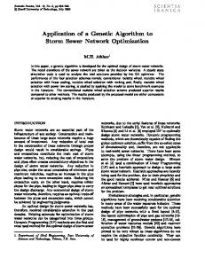
3. Structure & Theory of Antenna Structure of microstrip circular patch antenna is depicted in Figure 1. Here “a” and “ae” are the radius and effective radius of microstrip patch respectively. Patch has been modeled on LiTi ferrite substrate of thickness “h”. The dielectric constant and saturation magnetization ( 4π M s ) of substrate is 17.5 and 2200 Gauss respectively. Copyright © 2011 SciRes.
ferrite substrate
a
central conductor
ae
radiant source ground plane
h external sheath
Figure 1. Schematic diagram of microstrip circular patch antenna.
It has been established that, for a biased ferrite slab, a normal incident plane wave may excite two types of waves (ordinary and extraordinary wave). In the case of normal incident magnetic field biasing ordinary wave is same as the plane wave in the dielectric slab. On the other hand, the extraordinary wave is a TE mode polarized parallel to the biasing direction with its phase propagation constant Ke [17-20].
Ke =
Kd =
µeff =
w ε eff × µeff c
(1)
w ε eff c
(2)
µ2 − k2 µ
µ = 1+ k=
wo wm wo2 − w2
wwm wo2 − w2
(3) (4) (5)
where
= wo γ= H o and wm γ 4π M s where H o is the bias field, 4π M s is the saturation magnetization, γ is the gyromagnetic ratio as γ = 2.8 MHZ./Oe. To obtain good performance, there are many feeding methods, such as CPW in the ground feeding microstrip antenna, and CPW with stub patch feeding slot antenna. Considering impedance matching of patches coaxial feeding is generally preferred. Thus the far zone expressions for circular patch microstrip antenna are obtained as follows:
sin ( kh cos θ ) kaVe − jkr cos nϕ kh cos θ 2r × { J n +1 ( ka sin θ ) − J n −1 ( ka sin θ )}
Eθ t = j n
(6)
JSEA
Application of Genetic Algorithm for Optimization of Important Parameters of Magnetically Biased Microstrip Circular Patch Antenna
sin ( kh cos θ ) kaVe − jkr cos nϕ kh cos θ 2r × { J n +1 ( ka sin θ ) + J n −1 ( ka sin θ )}
Eϕ t = j n
(7)
where 12
w + wm w Kd o = k K= ± wo wm
4. Application of Genetic Algorithm to the Microstrip Antenna and Computed Result All the vital parameters like thickness of the substrate, bias magnetic field, radius, dielectric constant etc. were coded into 5 bit scaled binary coding as the requirement of fitness function. The Roulette wheel selection was used for GA population. The genetic algorithm was run for 500 generations. The probability of crossover was varied from 0.7 to 0.85 and the probability of mutation was varied from 0.001 to 0.002. The fitness functions expressions of antenna used for optimization are: Fitness Function: 1—Effective Radius 1
aeff
2h 2 πa = a 1 + log + 1.7726 2h π af
Fitness Function: 2—Radiation Power
Prad =
A 2 Z in
2π π
∫ ∫ Eθ t 0 0
2 + Eϕ t r 2 sin θ dθ dφ
)
2
1 × P 120 4 × rad
Fitness Function: 4—Input Impedance 1 Z in = ( 4 × Prad )
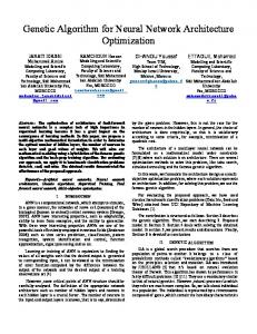
5. Results and Calculations Obtained Graphs (Figures 3-8) show the variation of best, mean and expected values of radiation power of antenna. During calculation GA program at every generation calculate expected value, mean and best value, then plot them for the corresponding parameter fitness functions. Every graph has a certain generation points above which convergence become very slowly and variation among mean and best values become negligible. All graphs (Figures 3-8) show the appreciate variation in mean values but in best value, carry a very little variation due to big generation attempt which precise or accurate the desired result. This big generation amount (500) has been applied to removing the inaccuracy in the best
(9)
(10)
(11)
Fitness Function: 5—Quality Factor
Qt = where
2
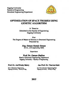
The antenna parameters have been characterized by a particular of combination of input variables like dielectric constant, patch radius and substrate thickness of the ferrite which is determined using cavity model. The GA consists of five components. These are the random number generator, a fitness evaluation unit and genetic operators for reproduction, crossover and mutation operations. The flow chart with proposed initial values of GA components, for optimization of parameters of microstrip antenna, is shown in Figure 2.
Fitness Function: 3—Directivity Dg =× ( k aeff
(8)
131
1 1 1 + + Qr Qd Qc
(12)
aeff × k Qr 2π cf × = h × 2 Prad 1 Qd = LT 12 Qc = h × (π f µσ )
Fitness Function: 6—Bandwidth
B=
( s − 1)
(Q × ( s )) 12
t
Copyright © 2011 SciRes.
(13) Figure 2. Flow chart of genetic algorithm applied for the optimization of parameters. JSEA
132
Application of Genetic Algorithm for Optimization of Important Parameters of Magnetically Biased Microstrip Circular Patch Antenna
Figure 3. Variation of best, mean and expected value of Eff. radius of circular patch antenna.
Figure 4. Variation of best, mean and expected value of radiation power of circular patch antenna.
Figure 5. Variation of best, mean and expected value of directive gain of circular patch antenna.
Copyright © 2011 SciRes.
JSEA
Application of Genetic Algorithm for Optimization of Important Parameters of Magnetically Biased Microstrip Circular Patch Antenna
133
Figure 6. Variation of best, mean and expected value of impedance of circular patch antenna.
Figure 7. Variation of best, mean and expected value of quality factor of circular patch antenna.
Figure 8. Variation of best, mean and expected value of band width of circular patch antenna. Copyright © 2011 SciRes.
JSEA
134
Application of Genetic Algorithm for Optimization of Important Parameters of Magnetically Biased Microstrip Circular Patch Antenna Table 1. Comparison of parameters calculated by GA program and experimentally obtained. Parameters
Opt. Values
Exp. Values
Eff. Radius
0.2082 cm
0.2100 cm
Rad. Power
0.2110 mW
0.2000 mW
Directive Gain
–10.05 dB
–9.55 dB
Impedance
138.88 ohms
100.55 ohms
Quality Factor
30.43%
28.40%
Bandwidth
–34.70 dB
–38.60 dB
result which can be judge by expected value graphs shown in every figure. The performance graphs (Figures 6 and 7) of Input impedance and quality factor show a little bit variation in best value, which shows the requirement of more generation attempt but could not be performed due to inefficiency of computer program. Calculated values of parameters of microstrip circular patch antenna with GA program have been compared with some theoretical and experimental results obtained by other methods and referenced in the research articles [21-31], which are in good agreement and given in Table 1.
6. Conclusions Designing the antenna with the optimum values of parameters over a given frequency range is an example of an optimization problem. The GA is very precise and fast compare to other techniques because it encodes the parameters, and the optimization is done with the encoded parameters. To design an antenna with best performance First, the problem should formulated for the size, shape, and material properties associated with the antenna. Next, an appropriate mathematical description that exactly or approximately models the antenna and electromagnetic waves is applied. Finally, numerical methods are used for the solution. One problem has one solution. Finding such a solution has proved quite difficult, even with powerful computers. Rather than finding a single solution, optimization implies finding many solutions then selecting the best one. Optimization is an inherently slow, difficult procedure, but it is extremely useful when well done. The difficult problem of optimizing an electromagnetics design has only recently received extensive attention. In the present communication the application of Genetic Algorithm for the optimization of important parameters of microstrip circular antenna printed on ferrite substrate is reported. The fitness functions for the GA program is developed using cavity method for the analysis of microstrip antenna. The computed graphs and results show a good agreement with the results obtained Copyright © 2011 SciRes.
experimentally.
REFERENCES [1]
R. L. Haupt, “An Introduction to Genetic Algorithms for Electromagnetics,” IEEE Transactions on Antennas Propagation Magazine, Vol. 37, No. 2, 1995, pp. 7-15. doi:10.1109/74.382334
[2]
N. Chattoraj and J. S. Roy, “The Optimization of Gain of Patch Antennas Using Genetic Algorithm,” ACTA Technica Ceskoslovensk Akademie Ved Academic Journal, Vol. 51, No. 3, 2006, pp. 279-287.
[3]
F. J. Villegas, T. Cwik, Y. Rahamat-Samii and M. Manteghi, “A Parallel Electromagnetic Genetic-Algorithm Optimization (EGO) Application for Patch Antenna Design,” IEEE Transactions on Antennas Propagation, Vol. 52, No. 9, 2004, pp. 2424-2435. doi:10.1109/TAP.2004.834071
[4]
A. M. Wyant, “Genetic Algorithm Optimization Applied to Planar and Wire Antennas,” Master Thesis, Rochester Institute of Technology, 2007.
[5]
A. Akdagli and K. Guney, “Effective Patch Radius Expression Obtained Using a Genetic Algorithm for the Resonant Frequency of Electrically Thin and Thick Circular Microstrip Antennas,” IEE Proceedings of Microwave and Antennas, Vol. 147, No. 2, 2000, pp. 156-159. doi:10.1049/ip-map:20000265
[6]
N. Chattoraj and J. S. Roy, “Investigations on Microstrip Antennas Covered with a Dielectric Layer Using Genetic Algorithm,” Union Radio-Scientifique Internationale Conference, New Delhi, 23-29 October 2005.
[7]
N. K. Saxena, A. Khan, P. K. S Pourush and N. Kumar, “Artificial Neural Network Analysis Optimization of Dielectric Constant & Side Length of Microstrip Triangular Patch Antenna,” International Journal of Computational Intelligence Research, Vol. 6, No. 1, 2010, pp. 165-170.
[8]
N. K. Saxena, A. Khan, P. K. S. Pourush and N. Kumar, “Neural Network Analysis of Switchability of Microstrip Rectangular Patch Antenna Printed on Ferrite Material,” International Journal of Radio Frequency and Microwave Computer-Aided Engineering, Vol. 20, No. 1, 2010, pp. 1-5.
[9]
T.-J. Chiu, Y.-T. Kuo, H.-Y. Chao and Y.-M. Li, “Optimization of Physics-Based Equivalent Circuits for Micro-
JSEA
Application of Genetic Algorithm for Optimization of Important Parameters of Magnetically Biased Microstrip Circular Patch Antenna strip Patch Antennas,” IEEE Antennas and Propagation Society International Symposium, Hsinchu, 9-15 June 2007, pp. 5785-5788. [10] D. R. Jackson and N. G. Alexopoulos, “Simple Approximation Formulas for Input Resistance, Bandwidth, and Efficiency of a Resonant Rectangular Patch,” IEEE Transactions on Antennas Propagation, Vol. 39, No. 3, 1991, pp. 407-410. doi:10.1109/8.76341 [11] G. León, R. R. Boix and F. Medina, “Tunability and Bandwidth of Microstrip Filters Fabricated on Magnetized Ferrites,” IEEE Microwave and Wireless Components Letters, Vol. 14, No. 4, 2004, pp. 171-173. doi:10.1109/LMWC.2004.827109 [12] G. León, R. R. Boix and F. Medina, “Full-Wave Analysis of a Wide Class of Microstrip Resonators Fabricated on Magnetized Ferrites with Arbitrarily Oriented Bias Magnetic Field,” IEEE Transactions on Microwave Theory Techniques, Vol. 50, No. 6, 2002, pp. 1510-1519. doi:10.1109/TMTT.2002.1006412 [13] H. How and T. M. Fang, “Drop-on Circulator Design at X and Ka Bands,” IEEE Transactions on Magnetics, Vol. 30, No. 6, 1994, pp. 4548-4550. doi:10.1109/20.334144 [14] J. H. Holland, “Adaptation in Natural and Artificial Systems,” University of Michigan Press, Ann Arbor, 1975. [15] D. E. Goldberg, “Genetic Algorithms in Search, Optimization, and Machine Learning,” Addison-Wesley, New York, 1989. [16] D. E. Goldberg, “Genetic Algorithms,” Addison-Wesley, New York, 1989. [17] Z.-F. Li, J. L. Volakis and P. Y. Papalambros, “Optimization of Patch Antennas on Ferrite Substrate Using the Finite Element Methods,” IEEE Transactions on Antennas Propagation, Vol. 41, No. 2, 1999, pp. 1026-1029. [18] D. M. Pozar, “Radiation and Scattering Characteristics of Microstrip Antennas on Normally Biased Ferrite Substrates,” IEEE Transactions on Antennas Propagation, Vol. 40, No. 10, 1992, pp. 1084-1092. doi:10.1109/8.166534 [19] L. Dixit and P. K. S. Pourush, “Radiation Characteristics of Switchable Ferrite Microstrip Array Antenna,” IEE Proceedings of Microwave and Antennas, Vol. 147, No. 2, 2000, pp. 151-155. doi:10.1049/ip-map:20000038 [20] M. S. Sodha and N. C. Srivastav, “Microwave Propagation in Ferrimagnetics,” Plenum Press, New York,
Copyright © 2011 SciRes.
135
1981. [21] R. Garg, P. Bhartia, I. Bahl and A. Ittipiboon, “Microstrip Antenna Design Handbook,” Artech House Inc., Norwood, 2001. [22] R. A. Stern, R. W. Babbit and J. Borowick, “A Mm-Wave Homogeneous Ferrite Scan Antenna,” Microwave Journal, Vol. 30, 1987, pp. 101-108. [23] A. Henderson, J. R. James and D. Frey, “Magnetic Microstrip Antenna with Pattern Control,” Electronics Letters, Vol. 30, 1988, pp. 101-108. doi:10.1049/el:19880031 [24] J. R. James, el al., “Magnetic Microstrip Antenna with Pattern Control,” Electronics Letters, Vol. 24, No. 19, 1988, pp. 45-47. doi:10.1049/ el:19880491 [25] D. M. Pozar, “Radar Cross-Section of Microstrip Antenna on Normally Biased Ferrite Substrates,” Electronics Letters, Vol. 25, No. 16, 1989, pp. 1079-1080. doi:10.1049/el:19890722 [26] J. S. Roy, P. Vaudon, A. Reineix, F. Jecko and B. Jecko, “Circularly Polarized Far Fields of an Axially Magnetized Circular Ferrite Microstrip Antenna,” Microwave and Optical Technology Letters, Vol. 5, No. 5, 1992, pp. 228-230. doi:10.1002/mop.4650050508 [27] J. S. Roy, P. Vaudon, A. Reineix, F. Jecko and B. Jecko, “Axially Magnetized Circular Ferrite Microstrip Antenna,” Proceedings of IEEE Antennas Propagation and Union Radio-Scientifique Internationale Conference Joint International Symposium, Chicago, 18-25 July 1992, pp. 22122215. [28] N. Das, S. K. Chowdhury and J. S. Chatterjee, “Circular Microstrip Antenna on a Ferrimagnetic Substrate,” IEEE Transactions on Antennas Propagation, Vol. 31, No. 1, 1983, pp. 188-190. doi:10.1109/TAP.1983.1142997 [29] J. S. Roy, P. Vaudon, F. Jecko and B. Jecko, “Magnetized Circular Ferrite Microstrip Antenna,” Proceedings of International Symposium on Antennas Propagation, Sapparo, 22-25 September 1992, pp 765-768. [30] J. S. Roy and N. Chattoraj, “Magnetically Biased Ferrite Micrsotrip Antenna,” Proceedings of Antenna and Propagation Symposium, Cochin, 21-23 Deceber 2002, pp. 288291. [31] J. J. Green and F. Sandy, “Microwave Characterization of Partially Magnetized Ferrites,” IEEE Transactions on Microwave Theory Techniques, Vol. 22, No. 6, 1974, pp. 641-645. doi:10.1109/TMTT.1974.1128306
JSEA
136
Application of Genetic Algorithm for Optimization of Important Parameters of Magnetically Biased Microstrip Circular Patch Antenna
Appendix: List of Symbols
Jn-1 = (n – 1)th order Bessel’s function of first kind
fr = resonant frequency
Ho = applied bias field
λ = wavelength
4πMs = saturation magnetization
h = height of substrate
γ = gyromagnetic ratio (2.8 MHz/Oe.)
a = radius of patch
Qt = total quality factor
aeff = effective radius of patch
Qr = total quality factor
εr = dielectric constant
Qd = total quality factor
εeff = effective dielectric constant
Qc = total quality factor
µr = initial permeability
LT = loss tangent of metal of patch (for copper = 0.0005)
µeff = effective permeability
σ = conductivity of metal of patch (for copper = 107)
µ, κ = permeability tensor components of µeff
s = voltage standing wave ratio (VSWR)
Kd = ordinary propagation constant
Prad = radiation power
Ke,± = extraordinary propagation constant
Zin = input impedance
ω = angular frequency of incident e-m-waves
B = bandwidth
ωo = external magnetic field angular frequency
Dg = directive gain
ωm = internal magnetic field angular frequency
Eθt = E-plane field
Jn+1 = (n+1)th order Bessel’s function of first kind
Eφt = H-plane field
Copyright © 2011 SciRes.
JSEA