Available online at www.sciencedirect.com
ScienceDirect Procedia Engineering 152 (2016) 454 – 458
International Conference on Oil and Gas Engineering, OGE-2016
Application of numerical methods for calculation of working processes in pneudraulic devices Vasilieva V.A.a, Chernyshev A.V.a* a
Bauman MSTU, Baumanskaya 2-ya st., 5/1, Moscow, 105005, Russian Federation
Abstract This article is devoted to the development of a combined method for working processes calculation in pneudraulic devices. The method is based on execution of interrelation between the mathematical models of the work processes in approximation of lumped and distributed medium thermodynamic state parameters and makes it possible to take into account irregularity of the pressure distribution inside a vessel. In the article this method is implemented on the basis of the low-end gas pressure regulator and the basic results of the computation and their concise analysis are presented. © 2016 2016Published The Authors. Published Elsevier Ltd.access article under the CC BY-NC-ND license © by Elsevier Ltd. by This is an open (http://creativecommons.org/licenses/by-nc-nd/4.0/). Peer-review under responsibility of the Omsk State Technical University. Peer-review under responsibility of the Omsk State Technical University Keywords: pneudraulic systems; pressure regulator; valve; lift force coefficient; distributed thermodynamic state parameters; lumped thermodynamic state parameters
1. Introduction At present the computational and theoretical methods [4, 6, 7] find ever-growing use for investigating the work processes in pneudraulic devices (PHD) [2]. These methods are more effective than performance of full-scale testing as far as the time and resources consumed are concerned, while qualitatively the picture obtained by calculation processes coincides with the real processes revealed as a result of the tests. There are two basic approaches to mathematical models development for conducting the computational and theoretical studies of the work processes: describing the work processes through approximation of lumped medium (liquid or gas) thermodynamic state parameters and describing the work processes through approximation of distributed medium thermodynamic state parameters. In the former case, it is assumed that the state parameters are measured similarly within the whole testing volume and do not depend on the coordinates of the considered point
* Corresponding author. Tel.: +7-499-263-6743. E-mail address:
[email protected]
1877-7058 © 2016 Published by Elsevier Ltd. This is an open access article under the CC BY-NC-ND license
(http://creativecommons.org/licenses/by-nc-nd/4.0/). Peer-review under responsibility of the Omsk State Technical University
doi:10.1016/j.proeng.2016.07.617
V.A. Vasilieva and A.V. Chernyshev / Procedia Engineering 152 (2016) 454 – 458
inside this volume, while in the other case the gas state parameters depend on the coordinates of the considered point within the testing volume. Most frequently in case of mathematical simulation of the work processes in the pneudraulic device a gas or liquid chamber of the device acts as a test volume. Each of the approaches has its own advantages and disadvantages. Thus, the description of the work processes through approximation of lumped thermodynamic state parameters is easily implemented and does not require great expenditure of computing capacities. Implementation of such an approach presents general ideas of the work processes occurring in the device, but does not allow to take into account inhomogeneity of the operating medium parameters within the considered volume, which actually takes place in the PHD chambers. The description of the work processes through approximation of distributed thermodynamic state parameters makes it possible to take into account the inhomogeneity of the operating medium parameters within the considered volume, but requires considerable processing power. This approach cannot be practically implemented for sophisticated pneudraulic systems. Thus it is important to develop the new methods of work processes computation in the pneudraulic devices that combine simplicity of implementation like in the use of lumped thermodynamic state parameters modeling method and at the same time completeness of description of the work processes ensured by the use of distributed parameters modeling method. 2. The study subject Such a method was developed by the article authors and tested on the example of the low-end gas pressure regulator (hereinafter referred to as the PR). PR design circuit is shown in Fig. 1. The PR is divided into five gas chambers, while the controlled member (CM) appears to be the sixth chamber. The physical processes equal in their volumes take place in these chambers. The structural elements are loaded with gas forces, elastic forces, and friction forces. The operating medium flow processes in the internal channels are replaced with the losses of fluid through conventional metering valves.
Fig. 1. Design circuit of pressure regulator with allowance for attached elements of the pneumatic system. P – pressure; T – temperature; V – volume; d – diameter; x–valve plate displacement; С - spring constant. Indexes 1…5 means number of the gas chamber. Indexes m and p means main and pulse valve accordingly.
The regulating element of the PR is made in the form of a valve plate. The technical literature concerned with the study of work processes in pneumatic valves shows that the inhomogeneity of pressure distribution in the device’s flow part substantially influences on the load acting on the regulating element and the flow of work processes. This should be taken into account in making preliminary computations in the course of designing and studying the device work. It is assumed that the difference between the effective gas force distributed over the whole valve plate area
455
456
V.A. Vasilieva and A.V. Chernyshev / Procedia Engineering 152 (2016) 454 – 458
and the gas static one acting on the valve seat area is allowed for by lift force coefficient φ [1, 3]. A detailed review of the publications concerned with these subjects is given in paper [5]. 3. Methods and Results of Studies The developed method is a combination of the work processes description methods for approximation of lumped and distributed gas thermodynamic state parameters and implies three stages. At the first stage the work processes in the pneumatic system consisting of the PR and CM are described by approximation of lumped gas thermodynamic state parameters. Each gas chamber is essentially an open thermodynamic system and the work processes inside it is describing by the classic thermodynamic relations: mass conservation equation, energy conservation equation, and ideal gas law [8]. The equations are reduced to the form of ordinary differential equations (ODE) and complemented with the closure equations (motion equations of the PR moving parts) and initial conditions. Solution of the obtained system is essentially the solution of the Cauchy problem for the first-order ODE. To find the solution, use is made of various numerical methods, which approximate the value of the integral for construction of the ODE numerical integration formulas make it possible to find the solution with the varying degree of accuracy. At the initial simulation stage, when the lift force coefficient is unknown, it is assumed that that the existing gas force is equal to the gas static one. The computation results are shown on Fig. 2.
Fig. 2. Variation of main valve displacement and pressure in flow part in a first approximation without allowance for lift force coefficient. P1, P2 – the pressure in chambers 1 and 2 accordingly; xm–main valve displacement; tp - the time of attaining mode.
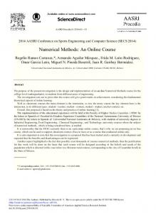
At this stage they carry out the program checkout, as well as determine the initial conditions required for solving the system of differential equations, which describe the gas state parameters in the flow part of the device as approximation of distributed thermodynamic state parameters at the second stage. At the second stage, the lift force coefficient is determined. To do this, the work processes are described in approximation of distributed thermodynamic gas state parameters. The operating medium parameters are described by the equations of continuity, motion, and energy [8]. This is the only method for obtaining a picture of distribution of pressures and determining the lift force coefficient acting on the PR regulating element. The computation results are given in Fig. 3 in the form of the pressure distribution in the PR flow chamber for a valve value of 5 mm.
V.A. Vasilieva and A.V. Chernyshev / Procedia Engineering 152 (2016) 454 – 458
Fig. 3. Distribution of pressures in the PR flow part.
The obtained results confirm the data contained in the scientific and technical literature [1, 3], which state that the pressure is unevenly distributed on the valve plate surface and that a pressure undershoot is formed in the subvalve sphere due to flow-around of the valve by the operating medium flow. Computations within the whole range of the valve lifting heights has shown that the reduced pressure zone under the valve increases with the rise of the valve, which also finds confirmation in the scientific and technical literature [3]. This is explained by the fact that at low lifting heights the operating medium moves in parallel with the seal plane and the pressure is nearly evenly distributed over the valve plate. With the increase of the valve plate lifting height over the seat the gas flow deflects from the plane parallel to the seal towards the valve axis and a pressure undershoot is formed in the subvalve sphere. Then, the lift force coefficient is determined. As the lift force coefficient is not a constant value within the whole range of the valve lifting heights, but varies due to the change of the flow area and pressures ahead of and past the valve, the graph showing the lift force coefficient variation depending on time is plotted. Then, the change over to the third stage takes place. At the third stage, integration is done: the computed meaning of the lift force coefficient is entered into the system of equations describing the work processes in the pneumatic system consisting of the PR and CM. The second and third stages are repeated until the deviation of the lift force coefficient meanings reaches required accuracy for all valve positions. The pictures of the distribution of pressures in the PR flow part do not undergo qualitative changes and only the pressure meanings are changed. The best computation results in the form of graphs showing variation of pressures in the PR flow part are presented in Fig. 4. To assess the extent of the lift force coefficient impact on the work processes in the PR, the points corresponding to the value of the main valve elevation by 5 mm are plotted on the graphs (Figs 2 and 4). When the results are compared, it is seen that the allowance for the lift force coefficient reduces the time, during which the valve reaches the specified point, from 1.4 to 1.3 s. Besides, the time of attaining mode tp by the PR is noticeably decreases. In addition, reduction of the pressure in the PR inlet chamber is observed in the point under consideration determined by computation with allowance for the lift force coefficient, while the pressure value in the PR outlet chamber does not practically change. This substantiates the assumption that the lift force coefficient is mostly affected by the pressure distribution in subvalve sphere, while the pressure in subvalve sphere is practically distributed evenly and has no substantial impact on the lift force coefficient [1].
457
458
V.A. Vasilieva and A.V. Chernyshev / Procedia Engineering 152 (2016) 454 – 458
Fig. 4. Variation of displacement of main valve and pressure in flow part with allowance for lift force coefficient. P1, P2 – the pressure in chambers 1 and 2 accordingly; xm–main valve displacement; tp - the time of attaining mode.
4. Conclusion So, as compared with the conventional computational methods, the use of this combined method made it possible to obtain a more accurate picture of the work processes occurring in the PR. Correlation of the calculation results with the experimental data found in the scientific and technical literature made it possible to draw a conclusion on their qualitative coincidence that permits to recommend this method for use in case of performing preliminary computations and studying the work processes in the PR. Basing on the developed computation method and mathematical models of the work processes further research can be carried out with the aim of analyzing the effect of various factors on the PR operation and perfection of the design. The conduct of studies with the aid of a generalized mathematical model of the work processes considerably cuts the time needed as compared with the experiment holding. Besides, the developed computation method can be applicable to various designs of the PR, as well as can be used for other PHDs, while the generalized mathematical model enables to simulate the work processes in new devices and attain the required performance characteristics of the system by way of selecting the design elements without use of experimental studies.
References [1] V.F. Bugaenko, Pneumatic automation space-rocket systems, Mechanical engineering, Moscow, 1979. [2] B.V. Karmugin, V.L. Kissel, A.G . Lazebnyk, Modern design of compact pneumatic valves, Technics, Kiev, 1980. [3] T.F. Kondratieva, Safety valves, Engineering, Leningrad, 1976. [4] A.V. Chernyshev, A.A. Krutikov, Modeling working processes in pneumatic devices with distributed parameters, Conversion in mechanical engineering. 4-5(2007), pp. 94-98. [5] A.V. Chernyshev, V.A. Vasilieva, A.A. Krutikov, N.N. Kolenko, Research of dynamic load acting on the pneumatic actuator of the regulating device, Bulletin of Bauman MSTU, P. "Engineering". 1 (2011), pp. 150-166. [6] A.V. Chernyshev, V.A. Vasilieva, P.I. Petropavlov, Mathematical modeling of the pressure regulator working processes taking into account energy dissipation, Compressors and Pneumatics. 12 (2012), pp. 24-31. [7] A.A. Krutikov, Creating a method of calculation and design of pneumatic actuators heating and cooling devices, Dis ... .cand. tehn. sciences (05.04.06) , Moscow, 2008. [8] L. G. Loytzyansky, Mechanics of liquid and gas, proc. for higher education institutions. 7 ed., Drofa, Moscow, 2003.