10th Annual Conference of the International FES Society July 2005 – Montreal, Canada
Application Programming Interface and PC control for the 8 channel stimulator MOTIONSTIM8 Negård N-O1,2, Schauer T1, Gersigny de J1, Hesse S3 and Raisch J2,1 1
Max Planck Institute for Dynamics of Complex Technical Systems, Magdeburg, Germany Lehrstuhl für Systemtheorie technischer Prozesse, Institut für Automatisierungstechnik, Otto-von-Guericke-Universität Magdeburg, Germany 3 Klinik Berlin, Dpt. Neurological Rehabilitation, Berlin, Germany 2
[email protected]
Abstract This work describes an application programming interface (API) for the commercially available 8 channel stimulator MOTIONSTIM8. The stimulator for transcutaneous FES applications is manufactured by the company Medel GmbH (Hamburg, Germany) and certified for clinical use. By use of the API, customised stimulation programs can be developed, including closed-loop applications. The user can therefore access various hardware interfaces. The functionality of the API will be outlined and an example application to an electro-mechanical gait trainer is described. For research purposes, computer control of the stimulator was further realised whereas the stimulator can be externally controlled through a serial interface (RS232).
1. INTRODUCTION The development of customised stimulation programs can be achieved either by graphical [1] or by syntactical programming (e.g. C). While the first allows fast implementation of simple programs also by non technical trained persons, the realisation of complex algorithms, especially feedback control, is often not possible. On the contrary syntactic programming languages offer a more flexible platform to implement more advanced algorithms. For the MOTIONSTIM8 stimulator both a graphical and a syntactical programming language are available. The latter will be described here. Before implementing standalone programs on a portable stimulator, it might be useful to implement and test control algorithms on a PC platform first by controlling the stimulator output through a serial interface. Often, the control of the stimulation frequencies is in this case realised by the PC software. This can however be a problem for non real-time
operating systems which do not offer reliable timing functions. For the MOTIONSTIM8, two modes have been designed for PC control allowing frequency control either by the stimulator or by the PC. Another feature of the PC interface is the possibility to generate doublets and triplets (high frequency pulse groups, typically 200 Hz).
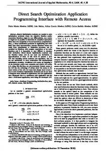
2. METHODS 2.1. Technical Data The current-controlled stimulator MOTIONSTIM8 by the company Medel GmbH1 offers a multiplexed current source for the 8 stimulation channels. The pulse widths, currents and frequencies can be adjusted individually for each channel (cf. Tab. 1). Table 1: Stimulator specifications Frequency Range 1-99 Hz
Current
Pulse width
0-125 mA 10-500 µs
Figure 1: Stimulator MOTIONSTIM8 Heart of the Stimulator is a Hitachi 32 Bit microcontroller (H8S/2633, 4MB RAM, 11 1
http://www.medel-hamburg.de
10th Annual Conference of the International FES Society July 2005 – Montreal, Canada
MHz). Two serial ports, one infra-red port, 5 analogue inputs (range 0...2.5V) as well as 3 digital I/O lines are available as hardware interfaces. Their specific use depends on the concrete application. To power up external sensors the battery voltage is made accessible with a maximal load of 100 mA. Galvanic isolation of the interfaces is not built-in and has to be realised by the user for the specific situation. The company Medel offers for serial communication a cable with built-in optocouplers. The generated pulses are rectangular biphasic with a delay of 100 µs between the positive and negative part of the pulse2. The stimulator has a dot matrix (128x68) liquid crystal display (LCD).
2.2. Application Programming Interface The C language programming interface consists of a series of functions and global variables. Most important is the control of the electrical stimulation. The stimulator provides a stimulation pulse generator which runs independently with a higher priority than the user program. The pulse generator is responsible for fulfilling the stimulation frequencies and pulse width timing. A user program can start and stop the pulse generator by the API. Activation of a channel as well as stimulation parameters (frequency, current amplitude and pulse width) can be updated with the API by means of global variables. This implementation yields stable stimulation frequencies. The price one has to pay is that perfect synchronisation of stimulation parameter updates and actual generation of the pulses is not possible. To achieve timing functionality, a timer with a resolution of 0.5 ms is provided through a global counter variable. Furthermore there are functions for serial communication, analoguedigital conversion (10 bit), digital I/O and LCD control. It should be noted, that writing to the LCD may take up to 80 ms which may be a limiting factor when implementing control algorithms. A more detailed description of the API is available from http://sciencestim.sf.net. A CDROM with the API is provided free of charge by the company Medel. The software runs under MS Windows.
2.3. Computer-Control Control of the MOTIONSTIM8 stimulator from an external device, preferably a PC, is possible via the standard RS232 interface. This mode, named ScienceMode, offers great flexibility
2
For 1 kΩ load
whereas two different approaches can be distinguished: Single Pulse Mode: Sending a command to the stimulator causes a single pulse been sent out on a specific channel with desired current amplitude and pulse width. The stimulator will generate the pulse immediately after processing the command. Complex stimulation patterns may be generated by sending more than one command. The external device is responsible for controlling the stimulation timing, i.e. the stimulation pulse interval. Channel List Mode: Using this mode, the generation of complex patterns is greatly simplified. The stimulator is responsible for controlling the stimulation timing. The user can specify a list of stimulation channels (channel list) on which pulses or even pulse groups (doublets or triplets) will be repeatedly generated. The inter pulse frequency of the doublets and triplets must however be constant for all channels. The main stimulation frequency of each channel can be chosen out of two specified stimulation frequencies whereas the higher available stimulation frequency is an integer of the lower available stimulation frequency. This option is useful when applying mixed reflex and muscle stimulation (e.g. 60 and 20 Hz). To enter the Channel List Mode an initialisation command must be issued by the external device. Another command is used to exit the Channel List Mode. While the Channel List Mode is active, the pulse parameters (pulse width, current amplitude and stimulation form (single pulse, doublet, or triplet) can be altered by sending a pulse parameter update command. The new parameters will be used for the next processing of the channel list. Single processing of the stimulation channel list can also be realised by a special initialisation of the Channel List Mode. After this, pulses are only generated by the update command. Now, the doublets and triplets are still generated by the stimulator, while the main stimulation frequencies are realised by the PC. The communication between the stimulator and the external device runs with 115200 Bit/s. The detailed protocol, an open source C++ library for Linux and MS Windows as well as a Matlab/Simulink interface are available from http://sciencestim.sf.net.
3. RESULTS The API was used to write a stimulation program for the electro-mechanical gait trainer developed by Hesse et al. [2]. The gait trainer shown in Fig. 2 allows wheelchair-bound
10th Annual Conference of the International FES Society July 2005 – Montreal, Canada
subjects the repetitive practice of a gait-like movement without over straining therapists. The device simulates the phases of gait by generating a ratio of 40% to 60% between swing and stance phases and by controlling the centre of mass in the vertical and horizontal directions. A servo-controlled drive mechanism assists the patients gait according to his or her abilities. The gait cadence can be chosen by the therapists and is then kept constant by the servo-controller. There exists already a solution to stimulate in paraplegics the quadriceps muscles during the stance phase. The gait trainer possesses a light barrier to detect the stance phases of each leg. This information is made accessible through switches which close when a leg is in the stance phase. The stimulator checks for the switches to be closed to synchronise the stimulation with the stance phases.
pressed, the switches become both closed. By detecting this event, stimulation is immediately turned off.
4. DISCUSSION AND CONCLUSIONS An open application programming interface (API) and PC control mode have been realised for a commercially available stimulator. Hopefully this will simplify the development and “getting into clinical practice” of new FES control algorithms. Researchers have now the possibility to implement new algorithms directly into commercially available hardware without the need of extensive support of stimulator manufactures. The feasibility of this approach has been demonstrated by a real word FES application; the FES supported gait in an electro-mechanical rehabilitation trainer.
In order to extend the number of stimulation channels and to allow a more gait-cycle specific, physiological stimulation, not only bound to the stance phase, a program for the MOTIONSTIM8 has been developed. For example, stimulation of the knee extensors also in the terminal swing phase for preparation of loading or stimulation of the plantar flexors to promote push-off are of clinical interest. The stimulator program observes the cadence of the gait by detecting the state of the switches. To determine the states, a simple resistor network was built, connecting the battery voltage, the switches at the gait trainer side and 2 analogue inputs of the stimulator. If constant cadence is achieved, the program estimates the current gait cycle percentage (GCP) by integration of the estimated cadence. Knowing the value of the GCP at any time makes a specific stimulation in predefined GCPintervals for up to 8 channels possible. The program offers comfortable menus for setting up GPC-intervals, current amplitudes, pulse widths and frequencies for the 8 channels individually. The stimulation can start as soon as a constant cadence has been detected. There is also the possibility to change current amplitude as well as GCP-intervals online while the stimulation is active. The stimulator offers rocker switches (digits on the stimulator, cf. Fig. 1) to adjust the parameters for each channel. When the cadence of the gait trainer is changing, stimulation will be switched off until constant cadence is detected again. The states (on, off) of the both switches for stance phase detection are normally opposite. If the emergency stop button on gait trainer is
Figure 2: Electro-mechanical gait trainer
References [1] Popovic MR, Keller T, Papas IPI, et al., Programmable and Portable Electrical Stimulator for Transcutaneous FES Application, In Proc. 6th IFESS Conference, Cleveland, USA, 2001. [2] Hesse S,Uhlenbroch D, Werner C,Bardeleben A. A Mechanized Gait Trainer for Restoring Gait in Nonambulatory Subjects. Arch. Phys. Med. Rehabil.,vol 81:1158-1161, 2000
Acknowledgements We would like to thank the company Medel for their support in developing the API and PC control interface for the MOTIONSTIM8. We further acknowledge the help of the Median-Klinik NRZ Magdeburg and the Klinik Berlin, Dpt. Neurological Rehabilitation, within this project.