specifically for dentistry, the New Tom 9000 (Quan- titative Radiology, Verona, Italy). ...... Hamilton, BC Decker 2007, p 55. 27. Maal TJJ, Plooij M, Rangel FA , et ...
J Oral Maxillofac Surg 68:1933-1959, 2010
Applications of 3-Dimensional Virtual Computerized Tomography Technology in Oral and Maxillofacial Surgery: Current Therapy Gary Orentlicher, DMD,* Douglas Goldsmith, DDS,† and Andrew Horowitz, DMD, MD‡ With the recent introduction of in-office cone-beam volumetric tomography scanners and the development of computed tomographic-based proprietary third-party 3-dimensional dental implant software programs, the field of implant dentistry is moving toward the 3-dimensional evaluation and placement of dental implants according to a restoratively driven treatment plan. The goal is to place the dental implant according to where the final dental restoration will be fabricated. The precision, accuracy, and 3-dimensional visualization capabilities of these technologies open avenues for the oral and maxillofacial surgeon in the diagnosis, planning, and surgical management of many nonimplant-related cases. The combination of these technologies is useful in expanding our information in dentoalveolar, preprosthetic, trauma, pathology and reconstruction, orthognathic and craniofacial, and cosmetic esthetic implant surgical cases. This article discusses the use of these technologies in the practice of oral and maxillofacial surgery. © 2010 American Association of Oral and Maxillofacial Surgeons J Oral Maxillofac Surg 68:1933-1959, 2010 Among dentists, oral and maxillofacial surgeons are most accustomed to using and evaluating computerized tomographic scans because of their in-hospital residency training and treatment of facial trauma, head and neck infections, oral pathology, and facial reconstruction. Until recently, the remainder of dental practitioners had little exposure or training in the radiographic evaluation of patients in 3 dimensions, relying primarily on conventional 2-dimensional, periapical, bitewing, and panoramic radiographs to evaluate patients and make diagnoses. Before the early 2000s, computed tomographic (CT) imaging was performed in a hospital setting or in a private radiology facility with a helical “medical” CT scanner. These technologies were not widely adopted by the dental community because of the costs, the difficult access to machines in hospitals, the perceived cost-benefit ratio when the extra radiation dos*Private Practice, Scarsdale, NY. †Private Practice, Scarsdale, NY. ‡Private Practice, Scarsdale, NY. Address correspondence and reprint requests to Dr Orentlicher: New York Oral, Maxillofacial, and Implant Surgery, 495 Central Park Avenue, Suite 201, Scarsdale, NY 10583; e-mail: oralsurgeons@ optonline.net © 2010 American Association of Oral and Maxillofacial Surgeons
0278-2391/10/6808-0034$36.00/0 doi:10.1016/j.joms.2010.03.013
age was considered, and the lack of familiarity and training in reading and interpreting the images. Mozzo et al1 in 1998 reported on the use of the first cone-beam volumetric tomographic (CBVT) machine specifically for dentistry, the New Tom 9000 (Quantitative Radiology, Verona, Italy). The technology allowed for less expensive, smaller, office-based machines that exposed the patient to lower radiation doses,2-4 but because of the lower radiation, somewhat less definition of bony images clinically. Since that time, multiple manufacturers have developed and marketed CBVT machines for the dental market. Because a discussion of the advantages and disadvantages of “medical” CT versus CBVT is not the subject of this report, the discussion to follow will use the term CT synonymously for both technologies. It is up to the individual clinician to decide which form of CT to use in an individual case. As early as the late 1980s, publications in the scientific literature began to appear discussing the use of DentaScans in the preoperative evaluation of the maxilla and mandible for dental implants.5-8 In 1988, Columbia Scientific Inc (Columbia, MD) introduced the 3D/Dental software. This software allowed radiologists to provide dental clinicians with reformatted, detailed, cross-sectional anatomic images of a patient’s alveolar ridges. In 1991, Columbia Scientific combined multiple software products into the ImageMaster-101 software, which allowed the place-
1933
1934
VIRTUAL CT IN ORAL AND MAXILLOFACIAL SURGERY
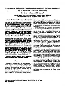
FIGURE 1. Impacted mandibular right third molar in close proximity to the inferior alveolar nerve. Orentlicher, Goldsmith, and Horowitz. Virtual CT in Oral and Maxillofacial Surgery. J Oral Maxillofac Surg 2010.
ment of graphical implants virtually onto CT images. In July 1993, the first version of Sim/Plant was released. With this software, the dental clinician could visualize a patient’s axial, cross-sectional, and panoramic views on 1 screen and place virtual implants. In 1999, with the introduction of Simplant 6.0, the ability to create 3-dimensional (3D) reformatted images was added to the software.9 In 2001, Materialise (Leuven, Belgium) purchased Columbia Scientific. The SurgiGuide technology for guided implant placement was introduced to the North American market by Materialise in 2002. NobelBiocare (Zurich, Switzerland) introduced the NobelGuide technology to the dental implant market in 2005. Software from other manufacturers, such as EasyGuide (Keystone Dental,
FIGURE 3. Left impacted mandibular third molar in intimate contact with the buccally positioned inferior alveolar nerve. Orentlicher, Goldsmith, and Horowitz. Virtual CT in Oral and Maxillofacial Surgery. J Oral Maxillofac Surg 2010.
FIGURE 2. Lower left mandibular third molar related to the inferior alveolar nerve. Note that the distal root appears to be surrounding the nerve.
FIGURE 4. Evaluation of the location of a mandibular left impacted premolar. A, Panoramic view and B, 3-dimensional reformation, lingual view (Simplant). Note the erosion of the distal root of the manibular left first molar.
Orentlicher, Goldsmith, and Horowitz. Virtual CT in Oral and Maxillofacial Surgery. J Oral Maxillofac Surg 2010.
Orentlicher, Goldsmith, and Horowitz. Virtual CT in Oral and Maxillofacial Surgery. J Oral Maxillofac Surg 2010.
1935
ORENTLICHER, GOLDSMITH, AND HOROWITZ
FIGURE 5. A 25-year-old female patient with the mandibular left third molar near the inferior alveolar nerve. A, Preoperative Panorex view. Preoperative computed tomographic scan: B, cross-sectional view and C, 3-dimensional reformation. Note that the root tips appear to be surrounding the inferior alveolar nerve (Simplant images). D, Postoperative Panorex view; coronectomy was performed on the mandibular left third molar and the mandibular right third molar was removed. Orentlicher, Goldsmith, and Horowitz. Virtual CT in Oral and Maxillofacial Surgery. J Oral Maxillofac Surg 2010.
Burlington, MA), VIP Software (BioHorizons, Birmingham, AL), and Implant Master (IDent, Foster City, CA), are currently available as well. Stereolithographic modeling, from CT data, has opened up new avenues for the diagnosis, evaluation, visualization, and treatment planning of patients in 3 dimensions. Companies such as Medical Modeling Inc (Golden, CO), Materialise, and others can fabricate exact 1-to-1 plastic models of a patient’s facial skeleton for evaluation, treatment planning, and even mock surgery. A surgeon’s goal is to maximize the amount of information he or she has before performing a surgical procedure to facilitate and expedite the surgical outcome successfully and minimize the surgical trauma and potential risks and complications to the patient. Using these 3D “virtual” technologies helps the surgeon facilitate these goals. As with the introduction of any new technologies, at times it is up to the creativity of the individual practitioner to recognize the applicability of using the technologies to gain valuable information or to help solve a surgical or reconstructive dilemma in an individual case. Discussions are starting to appear in the literature regarding the expanded applicability of these technologies in dentistry. Recently, Quereshy et
FIGURE 6. Supernumerary teeth (mesiodens), anterior maxilla: A, 3-dimensional reformation and B, cross-sectional view (Simplant images). Orentlicher, Goldsmith, and Horowitz. Virtual CT in Oral and Maxillofacial Surgery. J Oral Maxillofac Surg 2010.
1936
VIRTUAL CT IN ORAL AND MAXILLOFACIAL SURGERY
FIGURE 7. Multiple supernumerary and impacted maxillary teeth. Note the proximity of the supernumerary tooth above the apices of the maxillary left first molar (arrow). The tooth was removed with a Caldwell-Luc approach (Simplant images). Orentlicher, Goldsmith, and Horowitz. Virtual CT in Oral and Maxillofacial Surgery. J Oral Maxillofac Surg 2010.
al10 published a report discussing the applications of CBVT in oral and maxillofacial surgery practice. The purpose of this article is to show the applicability of using these, very powerful, 3D virtual technologies in the practice of oral and maxillofacial surgery. Office-based CT can produce more than advanced imaging. Three-dimensional virtual technologies in the areas of dentoalveolar surgery and impacted teeth, preprosthetic surgery, trauma, pathology, reconstruction, craniofacial and orthognathic surgery, and facial esthetic implants can provide superior assessment, planning, and outcome information in oral and maxillofacial surgery practice.
consistently more buccal or lingual, so the clinician often is functioning on his “best guess” based on panoramic radiographic signs.13 Considering that the reported overall incidence of inferior alveolar nerve injury secondary to third molar removal ranges from 0.5% to 8%,14-16 whereas the incidence of permanent
Dentoalveolar Surgery and Impacted Teeth The evaluation of patients for the removal of impacted and supernumerary teeth and determining the location of some teeth requiring surgical exposure is at times a very difficult assessment for an oral and maxillofacial surgeon. The proximity, angulations, and locations of these teeth, related to surrounding vital structures, such as the inferior alveolar nerve, incisive nerve, maxillary sinus, mental foramen, floor of the mouth, inferior border of the mandible, and adjacent teeth, can be difficult to adequately determine using conventional 2-dimensional periapical and panoramic radiographs. For the removal of impacted third molars, anatomic variations in the positioning of the mandibular nerve canal, especially in the buccal-lingual dimension, are difficult to assess using conventional 2-dimensional radiographic techniques.11,12 The buccal-lingual position of the mandibular canal has not been found to be
FIGURE 8. Horizontally impacted mandibular left canine (arrow): A, 3-dimensional reformation and B, cross-sectional view (Simplant images). Orentlicher, Goldsmith, and Horowitz. Virtual CT in Oral and Maxillofacial Surgery. J Oral Maxillofac Surg 2010.
1937
ORENTLICHER, GOLDSMITH, AND HOROWITZ
mandibular nerve injury is reported to be lower than 1%,16-18 it can be helpful for the surgeon who has a question about the preoperative position of a mandibular third molar, as it relates to the mandibular canal, to visualize that relation in 3 dimensions by viewing the anatomy with a preoperative CT scan.19 Friedland et al20 recently discussed the use of CT scans and 3D reconstructions, using the Simplant software, to evaluate the relation of the mandibular canal and impacted third molars. The use of these technologies to preoperatively evaluate supernumerary teeth requiring removal and impacted teeth requiring surgical exposure procedures provides the surgeon with the 3D information necessary to better determine the locations, angulations, and positions of these teeth as they relate to
vital structures and adjacent teeth in the areas. Using the software feature, segmentation, the sensitivity of the software to Hounsfield units can be altered. This allows the clinician to remove the surrounding bone from the images, thus allowing the visualization of the teeth as related to other isolated vital structures. Using these technologies in these cases can make the procedures less invasive and more efficient,21 minimizing patient morbidity and decreasing potential surgical complications (Figs 1-9E).
Preprosthetic Surgery In cases where implants are planned in sites of questionable quality, quantity, and/or contour of the bone, a preoperative CT scan of the maxillary
FIGURE 9. A 65-year-old female patient referred after bilateral posterior mandibular implant placement. A, Postoperative Panorex view. Computed tomographic cross-sectional views of B, lower right first premolar and C, lower left first premolar, D. Three-dimensional reformation views of the right side and E, left side. Note the proximity of the inferior alveolar nerve to the implants placed (Simplant images). Orentlicher, Goldsmith, and Horowitz. Virtual CT in Oral and Maxillofacial Surgery. J Oral Maxillofac Surg 2010.
1938
VIRTUAL CT IN ORAL AND MAXILLOFACIAL SURGERY
FIGURE 10. A 17-year-old female patient with bilateral congenitally missing maxillary lateral incisors and second premolar teeth, and the right canine tooth. After preoperative computed tomographic evaluation (Simplant software), grafting was performed as follows: right second premolar area, block chin graft laterally and small “sinus lift” vertically; right canine and lateral incisor areas, “ridge splitting” for added superior/lateral width; left lateral incisor area, block chin graft for width; left second premolar area, “sinus lift” graft for vertical height. Implants were placed in the sites using a NobelGuide 4 months after grafting. Preoperative images were done with Simplant. Images after grafting were done with NobelGuide software. A, Preoperative computed tomographic scan (Simplant) used for the preoperative evaluation of each implant site. “Virtual” implants are in place in their ideal restorative locations. Area of the upper right second premolar: B, preoperative cross-sectional view and C, view after a block chin graft and small “sinus lift” graft. Note the preoperative ridge measurements. Area of the upper right canine: D, preoperative cross-sectional image with ridge measurements and E, postgraft image after a “ridge splitting” procedure. Area of the upper left lateral incisor: F, preoperative cross-sectional image with a simulated block graft drawn (green) and ridge measurements and G, postgraft image after block chin graft. Area of the upper left second premolar: H, preoperative cross-sectional image with a simulated planned small “sinus lift” graft (green) and I, postgraft image. J, Postgraft 3-dimensional reformation image, frontal view. Note the distorted anatomy and titanium screws in place in the lateral augmentation areas. Orentlicher, Goldsmith, and Horowitz. Virtual CT in Oral and Maxillofacial Surgery. J Oral Maxillofac Surg 2010.
1939
ORENTLICHER, GOLDSMITH, AND HOROWITZ
FIGURE 11. A 52-year-old female patient with a prominent right maxillary sinus septum (arrows). Right maxilla, 4 views (Simplant). Orentlicher, Goldsmith, and Horowitz. Virtual CT in Oral and Maxillofacial Surgery. J Oral Maxillofac Surg 2010.
and mandibular alveolar ridges can be of great benefit to evaluate these areas and to plan the appropriate bone grafting procedures necessary to prepare the areas for implants. For example, the determination as to whether a block bone graft, “ridge splitting” graft, particulate bone graft, “sinus lift” graft, or distraction osteogenesis is the best procedure for a given site is best made after evaluating the area of concern in 3 dimensions, using a CT scan. If the doctor first reproduces the planned restorations by fabricating a radiographic guide for the patient to wear while having the CT scan, the doctor can then import the CT data into proprietary implant software programs (ie, Simplant, NobelGuide, or others). This allows the clinician to visualize the deficient bone in the planned implant site as it relates to the ideal position of the planned
restorations.22 Implants can then be placed “virtually” into their ideal positions related to the planned restorations, regardless of whether or not bone is present in these images. A determination of the exact location, amount, and volume of deficient bone in these sites can then be made preoperatively using the measurement and bone volume tools found in these software programs (Figs 10A-J). For a posterior maxilla deficient in height, anatomic variations such as the thickness of the lateral maxillary wall, the proximity of the site to the maxillary buttress, and the size and location of bony septae within the sinus (Figs 11, 12) can be determined before a sinus lift bone graft procedure. Intraoral block bone graft donor sites such as the chin or external oblique ridge areas can be evaluated preoperatively for thickness of the bone and proximity
FIGURE 12. A 50-year-old female patient with multiple bony septae, left maxillary sinus. Note that septae separate the maxillary sinus into vertical and horizontal compartments (arrows). Left maxilla, 4 views. Orentlicher, Goldsmith, and Horowitz. Virtual CT in Oral and Maxillofacial Surgery. J Oral Maxillofac Surg 2010.
1940
VIRTUAL CT IN ORAL AND MAXILLOFACIAL SURGERY
FIGURE 13. A 40-year-old female patient with 2 failed attempts at implant placement with grafting in the anterior mandible. Both attempts resulted in acute infection, implant failure, and severe alveolar bone and soft tissue loss. Reconstruction of the area involved a diagnostic computed tomogram for evaluation; fabrication of a metal-reinforced provisional restoration with ideal-sized teeth to show the size of the defect clinically; stereolithographic model fabrication (Medical Modeling, Golden, CO); prebending of a titanium mesh crib (StrykerLiebinger, Kalamazoo, MI); and placement of the crib with a graft of bone morphogenic protein (Medtronic, Minneapolis, MN) for later implant placement. A, Preoperative Panorex view shows that the implant in the area of the mandibular right first premolar is poorly placed. B, Preoperative intraoral image of the anterior defect. C, Metal-reinforced provisional restoration fabricated and in place. Note the size of the defect under the restoration. D, Preoperative computed tomogram, 4 views (Simplant). Note the extent of the anterior mandibular bone destruction and large bony defects. E, Stereolithographic model fabricated from computed tomographic data, frontal view (Medical Modeling). Titanium mesh (Stryker-Liebinger) prebent and secured using titanium screws. F, Prebent titanium mesh, side view. Note that the ridge creation is planned buccal to the existing defect. G, Exposure of the anterior mandibular defect. H, Prebent titanium crib holding bone morphogenic protein sponges in place. I, Postoperative Panorex view. Note that the titanium mesh is in place. Orentlicher, Goldsmith, and Horowitz. Virtual CT in Oral and Maxillofacial Surgery. J Oral Maxillofac Surg 2010.
ORENTLICHER, GOLDSMITH, AND HOROWITZ
1941
FIGURE 14. A 35-year-old male patient whose maxillary right lateral and central incisors, and left central incisor were avulsed as a young child from a wrestling injury. The resultant ridge was severely atrophic in height and width. The maxillary right canine and left lateral incisor teeth were nonrestorable. The treatment plan consisted of a computed tomographic scan evaluated using Simplant (Materialise, Glen Burnie, MD) for initial evaluation, measurements, and diagnosis; fabrication of a stereolithographic model (Medical Modeling); alveolar distraction osteogenesis planning by prebending an alveolar distractor (KLS Martin, Tuttlingen, Germany); testing the vector of distraction by performing preoperative mock “surgery” on the stereolithographic model; anterior maxillary osteotomy surgery to place the distractor according to the predetermined plan; block chin grafts to augment the distracted bone in width; and guided implant placement using a NobelGuide (NobelBiocare). Diagnostic computed tomogram with “ideal” barium teeth: A, 3-dimensional reformation showing the vertical discrepancy and B, cross-sectional image, through the area of the upper lateral incisor, showing the height and width deficiency. Note the measurements. C, Stereolithographic model fabricated from computed tomographic data (Medical Modeling), with the osteotomy outlined and the alveolar distractor (KLS Martin) prebent and secured in place with titanium screws. D, Distraction surgery performed on the stereolithographic model. The vector of distraction and possible bony interferences were tested. E, Osteotomy was performed, with the distractor in place, fully closed. F, The distractor was expanded and tested at the time of osteotomy surgery. G, Postdistraction Panorex view, with the distractor fully activated. H, Provisional restoration in place, with the distractor fully extended. Note that the restoration is carved out to allow access to the distraction post. I, Chin block grafts secured in place for width augmentation. Postoperative computed tomographic images (NobelGuide), in preparation for implant placement: J, 3-dimensional reformation, frontal view, and K, cross-sectional view of the maxillary right lateral incisor area. Note the postoperative 7.7 mm of crestal bone thickness and 16.3 mm of vertical height compared with the preoperative measurements of 4.3 and 9.5 mm in B, respectively. Orentlicher, Goldsmith, and Horowitz. Virtual CT in Oral and Maxillofacial Surgery. J Oral Maxillofac Surg 2010.
1942 of the available bone in these areas to nerves and root apices. Accurate measurements of these relations can be made preoperatively and then used, at the time of surgery, at these donor sites to harvest the donor bone grafts with less potential patient morbidity. Preoperative evaluation of patients requiring larger grafts including iliac crest grafts and grafts using bone morphogenic protein can be planned (Figs 13A-J). The ideal grafting procedure for an individual implant site can be preoperatively decided on based on this information. If alveolar distraction osteogenesis is planned, a preoperative CT scan can aid in determining the amount of vertical alveolar distraction necessary. A 1-to-1 stereolithographic model can be made from the CT scan data. Using these models preoperatively, the area to be distracted can be marked; the alveolar
VIRTUAL CT IN ORAL AND MAXILLOFACIAL SURGERY
distractor can then be prebent to fit the bone; and mock surgery can be performed by creating osteotomies in the plastic model and by securing the alveolar distractor to the model with titanium screws, similarly sized to those to be used during the surgery. This allows the surgeon to visualize the movement of the island of bone preoperatively. Adjustments can then be made in the direction and angulations of the distracted island of bone by altering the positioning of the alveolar distractor, before surgery. This minimizes the likelihood of unfavorable premature bony contacts as the island of bone is superiorly distracted. In addition, a determination of the ideal vector of movement of the island of bone can be made preoperatively, by altering the bending of the bone plates of the distractor to idealize this directional movement (Figs 14A-K).
FIGURE 15. A 75-year-old male patient with a pathologic fracture of his mandibular symphysis secondary to chronic infection. The fracture was treated with an open reduction using a stereolithographic model, a prebent titanium reconstruction plate (Stryker-Liebinger), and an iliac crest bone graft. A, Preoperative computed tomographic scan, 4 views (Simplant). Note the mandibular parasymphyseal fracture. B, Postoperative computed tomographic scan, with the reconstruction plate and graft in place. Orentlicher, Goldsmith, and Horowitz. Virtual CT in Oral and Maxillofacial Surgery. J Oral Maxillofac Surg 2010.
1943
ORENTLICHER, GOLDSMITH, AND HOROWITZ
FIGURE 16. A 50-year-old female patient with severe mandibular atrophy, fractured mandible, left body. Treatment included an open reduction with internal fixation using a titanium reconstruction plate (Stryker-Liebinger). A, Preoperative computed tomographic scan, 4 views. Note the fracture displacement in 3-dimensional reformation. B, Three-dimensional reformation, occlusal view. C, Postoperative computed tomographic scan, 3-dimensional reformation, fracture reduction with internal rigid fixation. Orentlicher, Goldsmith, and Horowitz. Virtual CT in Oral and Maxillofacial Surgery. J Oral Maxillofac Surg 2010.
Maxillofacial Trauma CT data from patients with maxillofacial trauma imported into implant software programs can provide 3D reformatted images that provide the trauma surgeon a unique perspective of the nature of the injury, the displacement of the fracture segments,
and the appropriate surgical approaches to the reduction and stabilization of the fracture(s). If desired, stereolithographic models can be made of the facial skeleton, providing the trauma surgeon with plastic models to aid in the diagnosis and treatment of these injuries. These models can also be helpful
FIGURE 17. A 9-year-old female patient with bilateral condylar fractures and a right mandibular body fracture from a bicycle accident. Fractures were reduced with an open reduction of the body fracture and a closed reduction of the condylar fractures. Cross-sectional computed tomographic views: A, right condylar fracture and B, left condylar fracture. C, Postoperative computed tomographic scan, 3-dimensional reformation. Note reduction of the right mandibular body fracture and postreduction condylar fracture positions. Orentlicher, Goldsmith, and Horowitz. Virtual CT in Oral and Maxillofacial Surgery. J Oral Maxillofac Surg 2010.
1944
VIRTUAL CT IN ORAL AND MAXILLOFACIAL SURGERY
small and large defects. Patients are commonly unprepared to deal with the resultant functional and, at times, the esthetic deformity. CT can be invaluable in localizing lesions, measuring the extent of the pathology, evaluating the involvement of surrounding vital structures and teeth in the pathologic lesion, evaluating the contours of the deformity created, and determining the volume of the potential bone graft necessary to reconstruct defects. Viewing the CT scan data in proprietary implant software programs, such as Simplant or NobelGuide, in 0.5- to 1-mm cross-sectional, axial, and panoramic views, with the 3D image reformation features of these programs, provides the surgeon important preoperative information to use in the planning, surgery, and reconstruction of maxillofacial pathology in patients. In addition, CT scan data can be used to create 1-to-1 stereolithographic models that can be used to mark the extent of surgical resections, prebend supporting reconstructive plates and frameworks, outline areas and determine bone volumes for reconstruction, and create supports for bone grafts. All of this can be done preoperatively, thus shortening surgical procedures, minimizing surgical trauma and patient
FIGURE 18. A 40-year-old female patient, 10 years after maxillary Le Fort I osteotomy and bilateral sagittal ramus osteotomies, sustained a fractured mandible, right parasymphysis, and bilateral condyles. The patient was treated by another practitioner with an open reduction with rigid fixation of the parasymphyseal fracture and a closed reduction of the condylar fractures. A, Postoperative computed tomographic scan, axial view, of displaced mandibular condylar fractures. B, Three-dimensional reformation, posterior view, showing displacement of condyles. C, Postoperative computed tomographic scan, lateral view. Note Class II skeletal relation and malocclusion. Orentlicher, Goldsmith, and Horowitz. Virtual CT in Oral and Maxillofacial Surgery. J Oral Maxillofac Surg 2010.
if the treatment of facial fractures has been delayed (Figs 15A-18C).23
Oral and Maxillofacial Pathology and Reconstruction Treatment of pathology can require extensive ablation of diseased and healthy tissue and bone, leaving
FIGURE 19. An 11-year-old male patient with a compound odontoma, maxilla. A, Computed tomographic scan, cross-sectional view, and B, 3-dimensional reformation (Simplant images). Orentlicher, Goldsmith, and Horowitz. Virtual CT in Oral and Maxillofacial Surgery. J Oral Maxillofac Surg 2010.
1945
ORENTLICHER, GOLDSMITH, AND HOROWITZ
morbidities, and maximizing patients’ functional and esthetic outcomes (Figs 19A-22C).
Orthognathic and Craniofacial Surgery Importing preoperative CT scans into proprietary implant software programs allows for the 3D visualization and assessment of the position of the lingula and the buccal-lingual and inferior-superior positions of the full length of the inferior alveolar nerve canal (Figs 23-25). The positions of the infraorbital nerve, the mental foramen, and the anterior loop of the mental nerve also are easily evaluated. Detailed measurements of the teeth and the anatomic relations of vital structures can be made using the measurement tools found in these software programs (Figs 26, 27). Preoperative evaluations and measurements of these types provide the oral and maxillofacial surgeon with 3D information that will translate into shortening surgical procedures and minimizing potential surgical risks and complications. Postoperatively, CT scans allow the surgeon to assess the positions of the osteotomy segments, bone plates and screws, bone grafts, and the mandibular condyles within the glenoid fossae. The visualization and evaluation of cleft lip and palate deformities traditionally has been done using a clinical examination in combination with panoramic, cephalometric, and occlusal radiographs. CT allows
for the 3D visualization of these patient’s deformities. Viewing these deformities in 3 dimensions, with 3D reformatting, benefits the doctor by allowing the preoperative evaluation of the size and limitations of the bony defect, the positions, condition, and maturation of teeth in the cleft site, and a method of determining the volume of bone necessary to successfully graft the cleft (Figs 28A,B). In maxillary and/or mandibular distraction cases, stereolithographic models of the jaws can be fabricated to evaluate the preoperative bony anatomy, prebend the distractors, and allow for mock surgery to evaluate the vector of the distraction and potential bony interferences (Figs 29A-30Q). The visualization of other, less common, craniofacial deformities is easier using 3D reformatting of CT data. For teaching and patient education purposes, Medical Modeling markets a set of 16, anatomically correct, stereolithographic cranial anomaly models, entitled The Craniofacial Model Skull Library. These models cover the spectrum of cranial anomalies from unilateral cleft lip/palate to Carpenter syndrome. Software programs are being developed to allow oral and maxillofacial surgeons to perform orthognathic surgery virtually. Maxillary and mandibular osteotomies, including segmental osteotomies, will be able to be performed first on a computer screen. Fabrication of maxillary and/or mandibular splints, for use at the time of orthognathic surgery to position the maxilla and/or
FIGURE 20. A 50-year-old female patient with a history of left partial maxillectomy secondary to a diagnosis of myxoma 25 years before presentation. The left maxillary reconstruction was performed using fabrication of a stereolithographic model, prebending of a titanium crib, and augmentation using bone morphogenic protein (Medtronic). A, Three-dimensional reformation of computed tomographic data (NobelGuide) showing the extent of the left maxillary bony defect. B, Three-dimensional reformation, frontal view. C, Titanium crib prebent (Stryker-Liebinger) and secured to the stereolithographic model (Medical Modeling), left side. D, Titanium crib secured to the stereolithographic model, occlusal view. E, Titanium crib try-in, intraoperative. F, Bone morphogenic protein–impregnated sponges within titanium mesh, intraoperative reconstruction. Orentlicher, Goldsmith, and Horowitz. Virtual CT in Oral and Maxillofacial Surgery. J Oral Maxillofac Surg 2010.
1946
VIRTUAL CT IN ORAL AND MAXILLOFACIAL SURGERY
FIGURE 21. A 19-year-old female patient with a diagnosis of ameloblastoma in the left mandible. A, Preoperative Panorex view. B, Preoperative computed tomographic scan, Simplant images. C, Stereolithographic model fabrication (Medical Modeling) with prebent titanium reconstruction plate (Stryker-Liebinger). D, Surgical view of iliac crest bone graft reconstruction. The reconstruction plate is in place. E, Postoperative Panorex view 6 months after iliac crest reconstruction. Implant placement was done using a NobelGuide. Orentlicher, Goldsmith, and Horowitz. Virtual CT in Oral and Maxillofacial Surgery. J Oral Maxillofac Surg 2010.
mandible, will be able to be ordered from these virtual treatment plans (Figs 31-35).24-28
Cosmetic Facial Esthetic Implants The ability to create customized facial implants, created and adapted to a patient’s specific bony anatomy, is an advantage of using 3D CT scan technology and stereolithographic modeling. Custom facial implants can be created for any area of the facial skeleton. The most common sites are the chin, malar, mandibular angle, and infraorbital regions.
Initially, a thorough clinical examination, including soft-to-hard tissue measurements, is performed. Typically, photographs and standard panoramic and cephalometric radiographs are taken. A cephalometric analysis is performed. A CT scan is ordered, usually with a field of view from the superior rim of the orbits through the inferior border of the mandible. A stereolithographic model from the CT scan data is then ordered. Modeling clay and wax are then used to create and carve a custom facial implant to the exact specifications, dimensions, and locations as determined by the clinical and radiographic examination
1947
ORENTLICHER, GOLDSMITH, AND HOROWITZ
FIGURE 22. A 9-year-old female patient with a diagnosis of central mucoepidermoid carcinoma of the right mandible. A, Panoramic radiograph on presentation. B, Preoperative computed tomographic images (Simplant). C, Three-dimensional reformation, computed tomographic scan (Simplant). Orentlicher, Goldsmith, and Horowitz. Virtual CT in Oral and Maxillofacial Surgery. J Oral Maxillofac Surg 2010.
and discussion with a patient. The custom wax carvings and the stereolithographic model are then sent for custom implant fabrication (Porex Surgical Inc,
Newnan, GA). The sterile custom implants are then placed using conventional intraoral or extraoral sterile surgical approaches (Figs 36A-37H).
1948
VIRTUAL CT IN ORAL AND MAXILLOFACIAL SURGERY
FIGURE 23. Computed tomographic scan of a 17-year-old female patient before orthognathic surgery. Note the inferior alveolar nerve is “drawn in” and isolated for the evaluation of its course before surgery. Orentlicher, Goldsmith, and Horowitz. Virtual CT in Oral and Maxillofacial Surgery. J Oral Maxillofac Surg 2010.
FIGURE 24. Computed tomographic scan (Simplant) before orthognathic surgery showing isolation and evaluation of the lingula (arrow).
FIGURE 26. Preoperative patient evaluation for genioplasty or chin augmentation (Simplant). Detailed preoperative measurements of the mental foramen and the anatomy of the chin are made. Orentlicher, Goldsmith, and Horowitz. Virtual CT in Oral and Maxillofacial Surgery. J Oral Maxillofac Surg 2010.
Orentlicher, Goldsmith, and Horowitz. Virtual CT in Oral and Maxillofacial Surgery. J Oral Maxillofac Surg 2010.
FIGURE 25. Detailed preoperative measurement of the location of the lingula in a preoperative orthognathic patient.
FIGURE 27. Computed tomographic scan, cross-sectional view, shows detailed measurements of the chin region before genioplasty or chin augmentation.
Orentlicher, Goldsmith, and Horowitz. Virtual CT in Oral and Maxillofacial Surgery. J Oral Maxillofac Surg 2010.
Orentlicher, Goldsmith, and Horowitz. Virtual CT in Oral and Maxillofacial Surgery. J Oral Maxillofac Surg 2010.
ORENTLICHER, GOLDSMITH, AND HOROWITZ
1949
FIGURE 28. An 18-year-old female patient with unilateral, right alveolar cleft. A, Computed tomographic scan, 4 views, of the unilateral right cleft alveolus (Simplant). B, Three-dimensional reformation of the right cleft alveolus. Note the clearly visible palatal cleft. Orentlicher, Goldsmith, and Horowitz. Virtual CT in Oral and Maxillofacial Surgery. J Oral Maxillofac Surg 2010.
1950
VIRTUAL CT IN ORAL AND MAXILLOFACIAL SURGERY
ORENTLICHER, GOLDSMITH, AND HOROWITZ
1951
FIGURE 29 (cont’d). A 17-year-old female patient with significant maxillary hypoplasia and Class III skeletal relation. The patient was treated with a preoperative computed tomographic scan, creation of a stereolithographic model, prebending of bilateral maxillary distractors (KLS Martin), mock surgery on the stereolithographic model, followed by maxillary surgical advancement by distraction osteogenesis. Six months after distraction osteogenesis, maxillary and mandibular osteotomies were performed. A, Preoperative lateral facial photograph. B, Preoperative intraoral photograph, frontal view. C, Preoperative lateral cephalometric radiograph. D, Preoperative computed tomographic scan, 3-dimensional reformations, frontal view. E, Preoperative stereolithographic model (Medical Modeling) made from computed tomographic data. Bilateral maxillary distractors (KLS Martin) were prebent and secured in place with titanium screws. Note the maxillary osteotomy cuts drawn in. F, G, Maxillary distractors were prebent and secured in place. Note the anterior-posterior discrepancy between the maxillary and mandibular dentitions. H, Lateral facial photograph after distraction and before maxillary and mandibular osteotomies. I, Intraoral photograph after distraction, frontal view. J, Panorex view after distraction. K, Postdistraction lateral cephalometric radiograph. L, Postdistraction computed tomographic scan, 3-dimensional reformations, lateral view. M, Final facial photograph, lateral view, after maxillary and mandibular osteotomies. N, Final intraoral photograph, frontal view. O, Final lateral cephalometric radiograph, after maxillary and mandibular osteotomies. Orentlicher, Goldsmith, and Horowitz. Virtual CT in Oral and Maxillofacial Surgery. J Oral Maxillofac Surg 2010.
1952
VIRTUAL CT IN ORAL AND MAXILLOFACIAL SURGERY
ORENTLICHER, GOLDSMITH, AND HOROWITZ
1953
FIGURE 30 (cont’d). A 15-year-old female patient was born with an incomplete expression of a cleft palate, multiple congenitally missing teeth, and associated atrophy and hypoplasia of her upper jaw. A concomitant severe Class III skeletal malocclusion was present. The patient first had full diagnostic records taken, including a computed tomographic scan. A stereolithographic model of her midface was made. Pediatric maxillary distractors were then prebent and custom fashioned for an anterior maxillary alveolar distraction. Four months after distraction, the distractors were removed. One month later, block chin grafts were performed to widen the elongated distracted alveolar bone for placement of implants using guided surgery (NobelGuide). Orthodontics was then completed and final restorations were fabricated. A, Preoperative facial photograph, lateral view. B, Intraoral photograph, frontal view. C, Preoperative computed tomographic scan of the maxilla, with 3-dimensional reformation. Note the incompletely closed hard palate, congenitally missing premolar teeth and associated alveolar bone, and dental arch space discrepancy. D, Stereolithographic model (Medical Modeling) fabricated from computed tomographic data. The maxillary anterior osteotomy is outlined. Pediatric maxillary distractors (KLS Martin) were prebent bilaterally and secured with titanium screws. Maxillary right distractor on E, the model and F, at the time of surgery. Maxillary left distractors on G, the model and H, at the time of surgery. I, Postoperative lateral cephalometric radiograph before activation of distractors. J, Postoperative lateral cephalometric radiograph of distractors fully activated. K, L, Five months after distraction, block chin grafts were placed in the distraction sites for additional width. M, Preoperative clinical occlusal photograph compared with N, the photograph of a model taken after maxillary anterior distraction and block chin graft. Note the increased alveolar space created. O, Treatment plan for guided implant placement (NobelGuide). P, Final frontal photograph with orthodontics in progress. Q, Final occlusal photograph with orthodontics in progress. Orentlicher, Goldsmith, and Horowitz. Virtual CT in Oral and Maxillofacial Surgery. J Oral Maxillofac Surg 2010.
FIGURE 31. Left, Three-dimensional surface model generated from computed tomographic data. Right, Augmented models show detailed dental anatomy (Maxilim software, courtesy of G. Swennen, NobelBiocare-Medicim, Mechelen, Belgium). Orentlicher, Goldsmith, and Horowitz. Virtual CT in Oral and Maxillofacial Surgery. J Oral Maxillofac Surg 2010.
1954
VIRTUAL CT IN ORAL AND MAXILLOFACIAL SURGERY
FIGURE 32. Three-dimensional surface representation of the skull (left) with linked lateral and frontal cephalograms (right) (courtesy of G. Swennen, Medicim). Orentlicher, Goldsmith, and Horowitz. Virtual CT in Oral and Maxillofacial Surgery. J Oral Maxillofac Surg 2010.
FIGURE 33. Computed tomogram-orthognathic surgical plan (left) and postoperative computed tomographic scan (right) (courtesy of N. Nadjmi, Medicim). Orentlicher, Goldsmith, and Horowitz. Virtual CT in Oral and Maxillofacial Surgery. J Oral Maxillofac Surg 2010.
ORENTLICHER, GOLDSMITH, AND HOROWITZ
1955
FIGURE 34. Preoperative (left), postoperative simulation (center), and postoperative (right) facial profiles (courtesy of N. Nadjmi, Medicim). Orentlicher, Goldsmith, and Horowitz. Virtual CT in Oral and Maxillofacial Surgery. J Oral Maxillofac Surg 2010.
FIGURE 35. Virtual fabrication of intermediary splint (center top) and final splint (center bottom) (courtesy of N. Nadjmi and G. Swennen, Medicim). Orentlicher, Goldsmith, and Horowitz. Virtual CT in Oral and Maxillofacial Surgery. J Oral Maxillofac Surg 2010.
1956
VIRTUAL CT IN ORAL AND MAXILLOFACIAL SURGERY
FIGURE 36. A 19-year-old male patient with maxillary vertical and horizontal excess and mandibular retrognathia and asymmetry. The patient refused an orthognathic surgical approach but agreed to a custom chin osteotomy and implant. A, B, Preoperative facial photographs. C, Preoperative lateral cephalometric radiograph. D, E, Preoperative computed tomographic 3-dimensional reformations. F, G, Stereolithographic model fabricated from computed tomographic data (Medical Modeling). H, Chin osteotomy, with ostectomy reproduced on the stereolithographic model. I, J, Custom chin implant created in clay on the stereolithographic model. (Fig 36 continued on next page.) Orentlicher, Goldsmith, and Horowitz. Virtual CT in Oral and Maxillofacial Surgery. J Oral Maxillofac Surg 2010.
ORENTLICHER, GOLDSMITH, AND HOROWITZ
1957
FIGURE 36 (cont’d). K, Postoperative lateral cephalometric radiograph. This chin osteotomy was stabilized with K wires, and the custom chin implant was stabilized with titanium screws. L, M, Postoperative clinical photographs.
1958
VIRTUAL CT IN ORAL AND MAXILLOFACIAL SURGERY
FIGURE 37. A 46-year-old male patient unhappy with his cheek bone projection desired zygoma implants. Custom wax implants were fabricated on a stereolithographic model and reproduced in Medpor (Porex Corp, Fairburn, GA) for placement surgically. A, B, Preoperative facial photographs. C, D, Preoperative computed tomographic 3-dimensional reformation. E, F, Stereolithographic model fabricated from computed tomographic data. G, H, Postoperative facial photographs after insertion of custom zygoma implants. Orentlicher, Goldsmith, and Horowitz. Virtual CT in Oral and Maxillofacial Surgery. J Oral Maxillofac Surg 2010.
ORENTLICHER, GOLDSMITH, AND HOROWITZ
References 1. Mozzo P, Procacci C, Tacconi A, et al: A new volumetric CT machine for dental imaging based on the cone beam technique: Preliminary results. Eur Radiol 8:1558, 1998 2. Mah J, Hatcher D: Three dimensional craniofacial imaging. Am J Orthod Dentofac Orthop 126:308, 2004 3. Hashimoto K, Yoshinori A, Kazui I, et al: A comparison of a new, limited cone beam computed tomography machine for dental use with a multi-detector row helical CT machine. Oral Surg Oral Med Oral Path Oral Radiol Endod 95:371, 2005 4. Sukovic P: Cone beam computed tomography in craniofacial imaging. Orthod Craniofac Res 6:31, 2003 (suppl 1) 5. Rothman SL, Chaftez N, Rhodes ML, Schwarz MS: CT in the preoperative assessment of the maxilla and mandible for endosseous implant surgery. Radiology 169:581, 1988 6. Casselman JW, Deryckere F, Hermans R, et al: Denta Scan: CT software program used in the anatomic evaluation of the mandible and maxilla in the perspective of endosseous implant surgery. Rofo 155:4, 1991 7. Villari N, Fanfani F: Diagnostic contribution of CT in implantology: Use of a new dental-scan reconstruction program. Radiol Med 83:608, 1992 8. Tal H, Moses O: A comparison of panoramic radiography with computed tomography in the planning of implant surgery. Dentomaxillofac Radiol 20:40, 1991 9. Web history—About CSI. Available at: http://sites.google.com/ site/simplantisrael/simplantsources. Accessed May 4, 2010 10. Quereshy FA, Savell TA, Palomo JM: Applications of cone beam computed tomography in the practice of oral and maxillofacial surgery. J Oral Maxillofac Surg 66:791, 2008 11. Klinge B, Petersson A, Maly P: Location of the mandibular canal: Comparison of macroscopic findings, conventional radiography, and computed tomography. Int J Oral Maxillofac Implants 4:327, 1989 12. Koong B, Pharoah MJ, Bulsara M, et al: Methods of determining the relationship of the mandibular canal and third molars: A survey of Australian oral and maxillofacial surgeons. Aust Dent J 51:64, 2006 13. Ohman A, Kivijarvi K, Blomback U, Flygare L: Preoperative radiographic evaluation of lower third molars with computed tomography. Dentomaxillofac Radiol 35:30, 2006 14. Rood JP: Permanent damage to inferior alveolar and lingual nerves during the removal of impacted mandibular third molars. Comparison of two methods of bone removal. Br Dent J 172:108, 1992
1959 15. Sisk AL, Hammer WB, Shelton DW, et al: Complications following removal of impacted third molars: The role of the experience of the surgeon. J Oral Maxillofac Surg 44:855, 1986 16. Bruce RA, Frederickson GC, Small GS: Age of patients and morbidity associated with mandibular third molar surgery. J Am Dent Assoc 101:240, 1980 17. Alling CC: Dysesthesia of the lingual and inferior alveolar nerves following third molar surgery. J Oral Maxillofac Surg 44:454, 1986 18. Wofford DT, Miller RI: Prospective study of dysesthesia following odontectomy of impacted mandibular third molars. J Oral Maxillofac Surg 45:15, 1987 19. Maegawa H, Sano K, Kitagawa Y, et al: Preoperative assessment of the relationship between the mandibular third molar and the mandibular canal by axial computed tomography with coronal and sagittal reconstruction. Oral Surg Oral Med Oral Pathol Oral Radiol Endod 96:639, 2003 20. Friedland B, Donoff B, Dodson TB: The use of 3-dimensional reconstructions to evaluate the anatomic relationship of the mandibular canal and impacted mandibular third molars. J Oral Maxillofac Surg 66:1678, 2008 21. Walker L, Enciso R, Mah J: Three-dimensional localization of maxillary canines with cone-beam computed tomography. Am J Orthod Dentofac Orthop 128:418, 2005 22. Orentlicher GP, Goldsmith DH, Horowitz AD: Thinking out of the box—The use of “virtual” implant treatment planning and surgery in challenging cases. Inside Dent 4:58, 2008 23. He D, Zhang Y, Ellis E: Panfacial fractures: Analysis of 33 cases treated late. J Oral Maxillofac Surg 65:2459, 2007 24. Swennenn GRJ, Mollemans W, Schutyser F: Three-dimensional treatment planning of orthognathic surgery in the era of virtual imaging. J Oral Maxillofac Surg 67:2080, 2009 25. Swennen GRJ, Mollemans W, De Clercq C, et al: A cone-beam CT triple scan procedure to obtain a three-dimensional augmented virtual skull model appropriate for orthognathic surgery planning. J Craniofac Surg 20:297, 2009 26. Swennen GRJ, Schutyser F: Three-dimensional virtual approach to diagnosis and treatment planning of maxillo-facial deformity, in Bell WH, Guerrero CA (eds): Distraction Osteogenesis of the Facial Skeleton (vol 6). Hamilton, BC Decker 2007, p 55 27. Maal TJJ, Plooij M, Rangel FA , et al: The accuracy of matching three-dimensional photographs with skin surfaces derived from cone-beam computed tomography. Int J Oral Maxillofac Surg 37:641, 2008 28. Swennen GRJ, Schutyser F: Three-dimensional cephalometry: Spiral multi-slice versus cone-beam CT. Am J Orthod Dentofac Orthop 130:410, 2006