Applying Control Theoretic Approach To Mitigate SIP Overload Yang Hong, Changcheng Huang, James Yan Dept. of Systems and Computer Engineering, Carleton University, Ottawa, Canada E-mail: {yanghong, huang}@sce.carleton.ca,
[email protected] Abstract—The Session Initiation Protocol (SIP) retransmission mechanism is designed to maintain reliable transmission over lossy or faulty network conditions. However, the retransmission can amplify the traffic overload faced by the SIP servers. In this paper, by modeling the interaction between an overloaded downstream server and its upstream server as a feedback control system, we propose two Proportional-Integral (PI) control algorithms to mitigate the overload by regulating the retransmission rate in the upstream server. We provide the design guidelines for both overload control algorithms to ensure the system stability. Our OPNET simulation results demonstrate that: (1) without the control algorithm applied, the overload at a downstream server may propagate to its upstream servers and cause widespread network failure; (2) in case of short-term overload, both proposed feedback control solutions can mitigate the overload effectively without rejecting calls or reducing resource utilization, thus avoiding the disadvantages of existing overload control solutions for SIP networks. Index Terms—Overload Control, Phase Margin, PI Rate Control, Server Crash, SIP, SIP Retransmission, System Stability
I. INTRODUCTION Internet protocol (IP) telephony is experiencing rapidly growing deployment due to its lower-cost telecommunications solutions for both consumer and business services. Session Initiation Protocol (SIP) [50] has become the main signaling protocol to setup, manage and terminate sessions for IP telephony applications such as Voice-over-IP, instant messaging and video conferencing [61]. SIP-based mobility management methods have been proposed to overcome the limitation of mobile IP and provide seamless mobility to the mobile terminals in an all-IP network infrastructure [51]. 3rd Generation Partnership Project (3GPP) [1] has adopted SIP as the basis of its IP Multimedia Subsystem (IMS) architecture [57]. With the
1
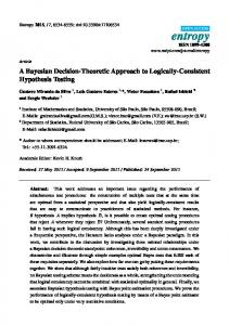
3rd Generation wireless technology being adopted by more and more carriers, most cellular phones and other mobile devices are starting to use or are in the process of supporting SIP [15]. Fig. 1 illustrates a simplified architecture of a SIP network. The two basic elements of a SIP network are: User Agent (UA) and Proxy Server (P-Server) [50]. A P-server not only acts as the contact point with UA for core network service access but also provides routing for the signaling messages. Each P-server is assigned to serve a large number of individual UAs. SIP is responsible for establishing, modifying and terminating sessions for multimedia communication among multiple UAs. A basic SIP operation will be reviewed in Section II. RFC 5390 [49] identified the various reasons that may cause server overload in a SIP network. These include but not limited to poor capacity planning, dependency failures, component failures, avalanche restart, flash crowds, etc. In general, anything that may trigger a demand burst or a server slowdown can cause server overload and lead to server crash. Existing Differentiated Service (DiffServ) mechanism proposed by Cisco [10] aims at providing scalable end-to-end Quality of Service (QoS) in the IP layer, but cannot solve SIP overload issues due to the following three aspects: (1) DiffServ mechanism is designed subject to the bandwidth constraint in the IP layer, while SIP overload is subject to the CPU constraint in the application layer; (2) DiffServ mechanism enhances QoS for different types of end-to-end data or media traffic which normally needs to traverse multiple hops before reaching their destination, but SIP overload is mainly caused by hop-by-hop signaling traffic between the neighbouring servers, because hop-by-hop transactions consume most of CPU resources [23, 53]; (3) DiffServ mechanism achieves endto-end QoS by differentiating different types of data or media traffic, where each source of data or media traffic sends large number of packets to its destination. However, each SIP UA only sends very few signaling messages to its destination for establishing a session [23]. Therefore, DiffServ mechanism cannot mitigate hop-by-hop SIP overload effectively. There are many published works [2, 3, 11, 12, 16, 18, 20, 22, 23, 26, 36, 37, 39, 40, 42, 43, 45, 46, 48, 52, 53, 56, 58, 59, 60] discussing how to control SIP overload through call rejection or load balancing. 2
These mechanisms can either increase call rejection rate or cause SIP server underutilized [33]. Rejecting calls can cancel the overload effectively, but it may cause a large amount of revenue loss to carriers [28, 30, 31]. We believe that arbitrarily high volume of call rejection can be avoided in most overload situations by developing overload control algorithms that address the root cause of server overloading and widespread SIP network failures. Domain B
Domain A Proxy Server
UA
Proxy Server
SIP Signaling
UA
Session
Internet Fig.1. Simplified architecture of a SIP network The objective of this paper is to develop two novel overload control algorithms through control theoretic approach that allows us to model the interaction between an overloaded downstream server and its upstream server as a feedback control system. Different from existing overload control solutions that try to mitigate the overload through rejecting calls or load balancing, our control approach will address directly unnecessary retransmissions. This is particularly useful when the overload is caused by short term demand bursts or temporary server slow down. For overloading caused by persistent demand surge or server slowdown, our solution can be used together with existing solutions to maximize server utilization. The contributions of this paper are: (1) Proposing two novel Proportional-Integral (PI) control algorithms to mitigate the server overload at a SIP network. Each algorithm detects the overload implicitly, and then regulates retransmission rate to prevent the overload propagation and the network collapse. Redundant Retransmission Ratio Control (RRRC) algorithm mitigates the overload by clamping redundant retransmission ratio around a target ratio, while Round Trip Delay Control (RTDC) algorithm tries to 3
clamp round trip delay below a target delay; (2) Extending classical control theory to model the interaction between a downstream server and its upstream server as a feedback control system. We have used the frequency domain technique to establish the stability of the two proposed control algorithms; (3) Providing the guidelines for obtaining PI controller parameters to guarantee the stability of the SIP overload control system. We perform OPNET simulation to validate the efficiency of two proposed SIP overload control solutions. The paper is organized as follows. Section II reviews SIP protocol briefly. Section III reviews existing SIP overload control solutions. Section IV investigates the impact of the retransmissions on the SIP overload. Section V proposes two different SIP overload control algorithms and applies the control theoretic approach in the controller design. Section VI verifies the validity of the proposed overload control algorithms using OPNET simulation. Conclusions are given in Section VII.
II. SIP PROTOCOL OVERVIEW Fig. 2 illustrates a basic operation of a SIP network. To set up a call, a User Agent Client (UAC) sends an “Invite” request to a User Agent Server (UAS) via the two proxy servers. The proxy server returns a provisional “100 (Trying)” response to confirm the receipt of the “Invite” request. The user agent server returns a “180 (Ringing)” response after confirming that the parameters are appropriate. It also evicts a “200 (OK)” message to answer the call. The user agent client sends an “ACK” response to the user agent server after receiving the “200 (OK)” message. Finally the call session is established between the user agent client and the user agent server through the SIP session. The “Bye” request is generated to close the session thus terminating the communication [50, 61]. When a SIP proxy server is overloaded, it will send a “503 Service Unavailable” message in response to an “Invite” message. The call will then be rejected. Processing SIP Invite messages and generating 503 Service Unavailable messages still consume a large amount of CPU time. Numerous experiment results (e.g., [23, 42, 52, 53]) have demonstrated that SIP
4
built-in overload control mechanism based on the 503 Service Unavailable messages cannot prevent overload collapse in a SIP network.
Fig. 2. A typical procedure of session establishment. SIP introduces a retransmission mechanism to maintain its reliability [19, 27, 50]. In practice, a SIP sender uses timeout to detect message losses. One or more retransmissions would be triggered if the corresponding reply message is not received in predetermined time intervals. SIP RFC 3261 [50] suggests that the SIP retransmission mechanism should be disabled for hop-byhop transaction when running SIP over Transmission Control Protocol (TCP) to avoid redundant retransmissions at both SIP and TCP layer [50]. However, recent experimental evaluation on SIP-over-TCP overload behaviour in [52] demonstrates that TCP flow control mechanism cannot prevent SIP overload collapse for time-critical session-based applications due to lack of application context awareness at the transport layer. Other experiments (e.g., [23, 42]) also indicate that the throughput with SIP-over-TCP exhibits similar overload collapse behaviour as that with SIP-over-UDP. Furthermore, IBM research center claims that using TCP to deliver SIP messages degrades server performance from 43% (under stateful
5
proxy with authentication) to 65% (under stateless proxy without authentication) when compared with using UDP [41]. Therefore most vendors choose to run SIP over UDP instead of TCP [17]. SIP has two types of message retransmission:
Hop-by-hop retransmission: a sender starts the first retransmission of an original message at
T1 seconds, the time interval doubling after every retransmission (exponential backoff), if the corresponding reply message is not received. The last retransmission is sent out at the maximum time interval 64xT1 seconds. Default value of T1 is 0.5s, thus there is a maximum of 6 retransmissions. The hopby-hop “Invite”“Trying” transaction shown in Fig. 1 follows this rule [50];
End-to-end retransmission: a sender starts the first retransmission of an original message at
T1 seconds, the time interval doubling after every retransmission but capping off at T2 seconds, if the corresponding reply message is not received. The last retransmission is sent out at the maximum time interval 64xT1 seconds. Default value of T2 is 4s, thus there is a maximum of 10 retransmissions. The endto-end “OK”“ACK” and “Bye”“OK” transactions shown in Fig. 1 follow this rule [50]. As the Invite message is the most complex message to be processed by a SIP server and thus the major CPU load contributor [50, 53], we will focus on the Invite-100Trying transaction and ignore other non-Invite transactions in this paper. Given the proportionate nature and the general similarity of the retransmission mechanisms between the “Invite” and “non-Invite” messages in a typical session [50], our two overload control algorithms are applicable for mitigating the overload caused by non-Invite transactions.
III. RELATED WORK Performance and reliability of a SIP network have been studied in [21, 54]. Experimental evaluation of SIP servers in [29, 34, 41] showed the overload collapse behaviour. The overload may spread in a network of SIP servers and bring a potential SIP network collapse [23, 32], therefore, different types of
6
strategies have been proposed to address SIP server overload problem (e.g., [2, 3, 11, 12, 16, 18, 20, 22, 23, 26, 36, 37, 39, 40, 42, 43, 45, 46, 48, 52, 53, 56, 58, 59, 60]). A. Load Balancing As a default part of numerous operating systems, SIP Express Router (SER) developed a load balancing module to mitigate the overload caused by large subscriber populations or abnormal operational conditions [36]. In order to balance the demands for bandwidth and the call failure rates of a SIP proxy, request batching was combined with parallel execution to improve call throughput and reduce call failure rate significantly in [11]. Three approaches were introduced for load balancing in cluster-based SIP servers [37]. The load balancer performed session-aware request assignment to route SIP transactions to the proper back-end nodes [37]. In an IMS core network, a load balancing scheme was proposed in [59] to re-direct consequent SIP traffic from the over-utilized Serving Call/Session Control Function (S-CSCF) server to the other underutilized ones. This can effectively drive the traffic to avoid further overload at potentially over-utilized SCSCF while not inducing severe extra load [59]. By providing efficient SIP message routing in the high volume Interrogating CSCF (I-CSCF) servers, a SIP message overload transfer scheme can leverage redundant servers to reduce the message disruption in cases of server failures [18]. A user equipment registration scheme not only balanced the workload over multiple Proxy-CSCF (P-CSCF) nodes, .but also reduced the required P-CSCF nodes up to 40% from the standard session initialization procedure of IMS [39]. However, load balancing tries to avoid SIP network failures by reducing the utilization of those servers that may become overloaded. When the total message arrival rate exceeds the aggregated processing capacity of all local servers, load balancing schemes cannot prevent the overload collapse. B. Priority-Based Overload Control
7
A priority enqueuing scheme provided differentiate service for different types of SIP messages in every SIP proxy server, where “INVITE” messages were placed into low priority queue [46]. Once the proxy server was overloaded, every “INVITE” message was hardly forwarded to its destination, thus forbidding the successive non-INVITE transactions to reduce the traffic load [46]. Another queuing strategy applied a queue threshold for the “INVITE” message queue to detect the overload in [16]. When the overload was anticipated, part of “INVITE” messages would be rejected to mitigate the overload by blocking the corresponding calls [16]. Priority queue was used to overcome the overload problem of IMS system by blocking non-priority calls (e.g., [3, 48]). Similar to the priority scheme, a novel authentication protocol was developed to reduce the load on the centralized authentication database dramatically and improve the overall security of a carrier-scale VoIP network in [12]. C. Push-Back Overload Control Since the CPU cost of rejecting a session is usually comparable to the CPU cost of serving a session [53], cancelling “INVITE” transaction using priority queuing scheme is not very cost-effective. Therefore, numerous push-back solutions have been proposed to reduce the traffic load of an overloaded receiving server by advertising its upstream sending servers to decrease their sending rates. Both centralized and distributed overload control mechanisms for SIP were developed in [23]. Retry-after control, processor occupancy control, queue delay control and window based control were proposed to improve goodput and prevent overload collapse in [43]. Three window-based feedback algorithms were proposed to adjust the message sending rate of the upstream SIP servers based on the queue length [53]. Other push-back solutions can be found in [2, 26, 40, 45, 52, 56, 58, 60]. Such pushback control solutions aim at preventing the overload of a server by reducing the sending rate of its upstream servers. This would increase the queuing delays of newly arrival original messages at the upstream servers, which in turn cause overload at the upstream servers. Overload may thus propagate server-by-server to sources. Unlike a source in TCP typically generates large amount of data, a UA in SIP 8
only generates very few signalling messages [23]. This leads to rejections of a large number of calls which means revenue loss for carriers. However, it may be unnecessary to reject calls when temporary overload only lasts a short period of time. D. Proposal of Retransmission-Based Overload Control Our approach proposed in this paper is different from the existing solutions discussed above. When retransmissions are caused by the overload rather than the message loss, they will bring extra overhead instead of reliability to the network and exacerbate the overload as we will demonstrate later through our analytical modeling and simulation. Therefore, when a short-term overload occurs at a downstream server, we propose to reduce the retransmission rate instead of reducing original message sending rate of its upstream servers. Such retransmission-based solution will mitigate the overload while maintaining original message sending rate, which leads to less blocking calls and more revenue for carriers [28, 30, 31]. Changing the SIP header requires a time-consuming standardization process. Therefore, for the ease of industrial implementation, our control algorithms locate the controller at each upstream server and request each upstream server to guess the overload at its downstream servers implicitly without any modification and extension to the SIP header. This is quite different from most existing push-back solutions which require some modification to the SIP header. When an overload lasts for a long period, our retransmission-based solution can be combined with pushback solution to reject some calls by reducing the original message rates of SIP sources. Under this kind of situation, our solution can help maximize server utilization and therefore serve as a complementary mechanism to the existing solutions On the other hand, RTDC algorithm proposed in this paper can also be used to reduce both retransmission rate and original message rate for mitigating a long-term overload, if SIP service providers are reluctant to modify the SIP header due to the time-consuming standardization process and expensive implementation cost. 9
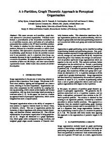
IV. QUEUING DYNAMICS OF OVERLOADED SERVER In order to provide effective overload control solutions, it is necessary to understand the impact of retransmission mechanism on the SIP overload. To achieve this goal, we need to analyze the queuing dynamics of an overloaded server and its upstream server when a transient overload occurs. The network topology of a real SIP system can be quite complex. Fig. 3 depicts a typical SIP network topology [28, 29, 30, 31, 53]. To focus our study on the interactions between overloaded receiving Server 2 and its upstream sending Server 1, we assume the upstream servers of Server 1 and the downstream servers of Server 2 have sufficient capacity to process all requests, retransmissions, and response messages immediately without any delay. Practical buffer sizes vary with the actual service rates and system configuration plans. With the memory becoming cheaper and cheaper, typical buffer sizes are likely to become larger and larger. We assume that the buffer sizes for all servers are large enough to avoid message loss. Instead, we focus on the queuing delay caused by the overload, which may trigger premature retransmissions.
Fig. 3. SIP network topology with an overloaded downstream receiving Server 2 (which is marked with diagonal lines) and its upstream sending Server 1.
100Trying response Invite request 1(t) r1(t) r2' (t ) Timer fires
Message buffer q1(t) Reset timer
Timer expires
qr1(t)
Invite request Server 2 2(t) 2 1 r2(t) Server 1 2(t) q2(t) 1(t) 100Trying response Timer starts
Timer buffer
Fig. 4. Queuing dynamics of an overloaded server and its upstream server. 10
Fig. 4 depicts the queuing dynamics of Server 1 and Server 2. There are two queues at each server: one to store the messages and the other to store the retransmission timers [23, 53]. We can obtain the queuing dynamics for the message queue of Server 2 as q 2 (t ) 2 (t ) r2 (t ) 2 (t ) 2 (t ) ,
(1)
where q2(t) denotes the queue size and q2(t)0; 2(t) denotes original message rate; r2(t) denotes retransmission message rate; 2(t) denotes response message rate; 2(t) denotes the message service rate. Like Eq. (1), we can obtain the queuing dynamics for the message queue of Server 1 as q1 (t ) 1 (t ) r1 (t ) r2(t ) 1 (t ) 1 (t ) ,
(2)
where q1(t) denotes the queue size and q1(t)0; 1(t) denotes aggregated arrival rate of original requests, which can be arbitrary stochastic process (e.g., Poisson, Pareto, Gamma or Lognormal distribution [13, 55]); r1(t) denotes retransmission message rate corresponding to 1(t); r'2(t) denotes retransmission message rate generated by Server 1 for 2(t); 1(t) denotes response message rate corresponding to 1(t), and the response messages will remove the corresponding retransmission timers from timer queue qr1; 1(t) denotes the message service rate. Note that the mean arrival rate 1 is equal to the inverse of the mean message inter-arrival time 1 , i.e., 1 1 / 1 . When the inter-arrival time of requests is used to describe the characteristics of a queuing process, a probability is typically used to express the relationship between the inter-arrival time and the arrival rate, i.e., by picking an arbitrary message arrival time as the starting point, and letting 1 be the time t until the next message arrival, we can obtain a probability P( 1 t ) e 1 , where 1 is the mean arrival rate.
Such probability describes the statistical nature of a stable queuing process, but cannot reflect dynamical behaviour of an unstable SIP queuing process in case of an overload. In order to demonstrate the root cause of the overload collapse, we describe the dynamical behaviour of a SIP queuing process in the continuoustime domain using Eqs. (1) and (2). 11
When Server 2 performs its routine maintenance and reduces its service capacity for signaling messages, the original message rate 2(t) is larger than the service rate 2(t), the queue size q2(t) tends to increase according to Eq. (1) (i.e., q 2 (t ) 0 ). After a short period, the queuing delay of Server 2 is long enough to trigger the retransmissions r'2(t) which enter the queue of Server 1. If the total new message arrival rate of 1(t), 1(t), and r'2(t) is larger than the service rate 1(t), the queue size q1 would increase (i.e., q1 (t ) 0 , as indicated by Eq. (2)) and may trigger the retransmissions r1(t) to bring the overload to Server 1.
After a queuing and processing delay at Server 1, the retransmitted messages r'2(t) enter Server 2 as r2(t) to increase the queue size q2(t) more quickly (as described by Eq. (1)), thus making the overload at Server 2 worse. In summary, we use Eqs. (1) and (2) to show how an overloaded downstream Server 2 propagates its overload to its upstream Server 1 under SIP retransmission mechanism. When the message arrival rate exceeds the message processing capacity at a SIP server, overload occurs and the queue builds up, which may result in a long queuing delay and trigger unnecessary message retransmissions from its upstream servers. The redundant retransmissions increase the CPU loads of both the overloaded server and its upstream servers. Such overload propagation may bring potential SIP network collapse.
V. PI CONTROLLER FOR MITIGATING SIP OVERLOAD Through the queuing analysis in the last section, we have demonstrated the impact of retransmissions on the SIP overload, that is, the unnecessary retransmitted messages r'2(t) triggered by the queuing delay would increase queue sizes at both Server 1 and Server 2, and thus bring the overload to both servers. Therefore, we believe that reducing the retransmission rate r'2(t) can prevent the queue sizes at both Server 1 and Server 2 from increasing continuously, thus mitigating the overload. To achieve our goal of mitigating the SIP overload, we propose two PI control algorithms (i.e., Redundant Retransmission Ratio Control algorithm and Round Trip Delay Control algorithm) to reduce
12
unnecessary retransmissions based on two different overload indicators (i.e., redundant retransmission ratio and round trip delay). The PID controllers are not necessarily optimal, and it is estimated that present sophisticated controllers would not have more economic effect in 80% of control loops [9]. Furthermore, the derivative action would amplify the noise and may deteriorate the system performance, therefore the industry widely employs PI controller instead of PID controller in the system design [5, 7, 14]. In addition, the stochastic nature of SIP traffic [13, 55] would make PI controller exhibit better performance than PID controller, thus we apply PI controller in SIP overload control. A. Redundant Retransmission Ratio Control Algorithm Redundant Retransmission Ratio Control (RRRC) algorithm aims at mitigating the overload by clamping the redundant retransmission ratio around a target value. 1) Overload Control Plant: Only a retransmitted message for message loss recovery is a nonredundant request message as well as an original message, while a retransmission caused by the overload delay is redundant. Thus a response message corresponding to a redundant retransmitted message is redundant. When overload happens, most retransmitted messages r'2(t) are redundant retransmitted messages r'2r(t), i.e., r'2r(t)r'2r(t) [53]. After a round trip delay , these redundant retransmitted messages r'2r(t) are acknowledged as the response messages 1r(t), i.e., 1r(t)=r'2r(t)r'2(t). We define the redundant retransmission ratio as the ratio between the redundant response message rate 1r and the total response message rate 1, i.e.,
(t)=1r(t)/1(t) r'2(t)/1(t).
(3)
In the real-time implementation, we count the number N1r of the arrival redundant response messages and the number N1 of the total arrival response messages during a sampling time interval Ts, then we can obtain 1r and 1 as 1r=N1r/Ts and 1=N1/Ts. Considering average 10% packet loss in the IP layer
13
[35], it is necessary to maintain a target redundant retransmission ratio 0 for message loss recovery. Our numerous experiments suggest that 0=0.1 is a good choice. We assume that the system is locally stable and therefore the uncontrolled variables and 1(t) are constant around an operating point. The transfer function between the instantaneous redundant retransmission ratio (t) and the retransmission rate r'2(t) is given by P(s)=(s)/r'2(s)=ࣦ{(t)}/ࣦ{r'2(t)}=[r'2(s)e-s/1]/r'2(s)=e-s/1.
(4)
Fig. 5 depicts a feedback SIP overload control system, where the overload control plant P(s) represents the interaction between an overloaded downstream receiving server and its upstream sending server, and adaptive PI controller C(s) is located at the upstream server for mitigating the overload to achieve a desirable target redundant retransmission ratio 0, when the overload is anticipated at the downstream server.
Fig. 5. Feedback SIP overload control system with target redundant retransmission ratio as system input. 2) The PI Rate Controller Design: Based on the instantaneous redundant retransmission ratio (t), the retransmission rate r'2(t) can be obtained by the following PI control algorithm expressed via t
t
0
0
r2 (t ) K P e(t ) K I e( )d K P ( 0 (t )) K I ( 0 ( ))d .
(5)
where KP and KI denote the proportional gain and integral gain of the PI controller at the upstream server. The goal of PI controller is to clamp the system output (i.e., instantaneous redundant retransmission ratio
(t)) around a target value (i.e., target redundant retransmission ratio 0) [44]. When the overload triggers excessive redundant retransmissions and makes redundant retransmission ratio (t) exceed 0 continuously, PI controller indicated by Eq. (5) will reduce retransmission rate and clamp (t) back to 0. In the real-time
14
implementation, a retransmission probability is equal to the ratio between the retransmission rate r'2(t) and the measured timer expiration rate. It can be easy to obtain the transfer function between the retransmission rate r'2(t) and the redundant retransmission ratio deviation e(t) as C(s)=KP+KI/s.
(6)
Since the control plant described by Eq. (4) is valid only during the overload period, we only activate the PI control algorithm when overload happens. The open-loop transfer function of overload control system becomes G(s)=C(s)P(s)=(KP+KI/s)e-s/1.
(7)
Nyquist Stability Theorem demonstrates that a positive phase margin (m>0) can guarantee the stability of a control system [44]. A common control engineering practice suggests an interval of phase margin as 300m600 for a good response [24]. From the definition on the phase margin m of G(s) [44], we can obtain
K arctan P g g m , 2 KI
K P2 g2 K I2 e
g
j g
1
K P2 g2 K I2
g1
(8)
1,
(9)
where g is the gain crossover frequency of the overload control system. To simplify our controller design, we set Kpg=KI. Thus we can rewrite Eqs. (8) and (9) as
g 3 / 4 m ,
(10)
2 K I /( g1 ) 1 .
(11)
Using the relationship KP=KI/g, we can obtain KP and KI from Eqs. (10) and (11) as
K P 1 / 2 ,
(12)
K I 1 (3 / 4 m ) /( 2 ) .
(13)
15
So far we have assumed 1 and be constant. In reality, this is not necessarily true. If the PI controller parameters KP and KI are kept constant, the varying queuing dynamics of the overloaded server may cause the change in two SIP network parameters (1 and ), thus may drive the phase margin to negative and the overload control system into instability. Theorems 1 and 2 show the impact of the two SIP network parameters on the phase margin or the system stability. Theorem 1: If the current round trip delay ' is longer than the previous round trip delay (i.e., '>) and the PI controller is designed based on , then the overload control system with ' will have less phase margin than that with (that is, 'm1) and the PI controller is designed based on 1, then the overload control system with '1 will have less phase margin than that with 1 (that is, 'm