IEEE TRANSACTIONS ON POWER SYSTEMS, VOL. 21, NO. 2, MAY 2006
559
Applying Multi-Agent System Technology in Practice: Automated Management and Analysis of SCADA and Digital Fault Recorder Data Euan M. Davidson, Stephen D. J. McArthur, Member, IEEE, James R. McDonald, Senior Member, IEEE, Tom Cumming, and Ian Watt
Abstract—This paper reports on the use of multi-agent system technology to automate the management and analysis of SCADA and digital fault recorder (DFR) data. The multi-agent system, entitled Protection Engineering Diagnostic Agents (PEDA), integrates legacy intelligent systems that analyze SCADA and DFR data to provide data management and online diagnostic information to protection engineers. Since November 2004, PEDA agents have been intelligently interpreting and managing data online at a transmission system operator in the U.K. As the results presented in this paper demonstrate, PEDA supports protection engineers by providing access to interpreted power systems data via the corporate intranet within minutes of the data being received. In this paper, the authors discuss their experience of developing a multi-agent system that is robust enough for continual online use within the power industry. The use of existing agent development toolsets and standards is also discussed. Index Terms—Cooperative systems, decision support systems, fault diagnosis, intelligent systems, knowledge-based systems, power transmission protection.
I. INTRODUCTION
R
ECENT research has investigated the potential application of multi-agent systems (MAS) technology [1] to a range of problems in power engineering. The use of multi-agent systems and architectures has been proposed for market simulation [2], [3], power system restoration [4], condition monitoring [5], [6], substation automation [7], alternative approaches to protection [8], the control of microgrids [9], and dealing with power system vulnerability [10]. Market simulation aside, results reported in the literature on the use of multi-agent system approaches to operational power systems functions have been either conceptual multi-agent system designs or architectures [10] or results from laboratory-based experiments [6], [9]. According to Wooldridge and Jennings [11], the migration of an agent system from prototype to a solution that is robust and Manuscript received May 4, 2005; revised August 18, 2005. Paper no. TPWRS-00272-2005. E. M. Davidson, S. D. J. McArthur, and J. R. McDonald are with the Institute for Energy and Environment, University of Strathclyde, Glasgow, G1 1XW, U.K. (e-mail:
[email protected];
[email protected];
[email protected]). T. Cumming and I. Watt are with SP PowerSystems plc, Motherwell, ML1 2RA, U.K. (e-mail:
[email protected]; ian.watt@ sppowersystems.com). Digital Object Identifier 10.1109/TPWRS.2006.873109
reliable enough to be used in practice is a nontrivial step. In this paper, the authors report on their experience of taking a prototype multi-agent system from the laboratory and applying it online at SP PowerSystems plc, a transmission system operator in the U.K. The multi-agent system in question is called Protection Engineering Diagnostic Agents (PEDA). PEDA uses multi-agent system technology to integrate a number of disparate legacy data analysis and retrieval systems in order to automatically collate and analyze power system data relating to protection operation. These data analysis tools include: a rule-based expert system that interprets SCADA data; a rule-based expert system that classifies and interprets digital fault recorder (DFR) data; and a model-based reasoning (MBR) system that validates protection operation. Earlier work by McArthur et al. [12] established that integration of the data analysis tools above could enhance diagnostic support by using the results of the analysis of SCADA data to prioritize the retrieval and analysis of DFR data. Practical considerations, however, made integration difficult: the software and hardware associated with monitoring equipment is liable to change as new monitoring technologies become available; any integration strategy has to allow the addition of new data sources, improved data analysis tools, and version changes to manufacturers’ software. In response to these requirements, Hossack et al. [13] proposed MAS technology as a medium for system integration because of the flexibility and extensibility it offers. A prototype version of PEDA was developed, and the results of testing using historical data were presented in [14]. Since November 2004, a number of the PEDA system’s agents have been analyzing and managing data online at SP PowerSystems. We believe that the results presented in this paper are among the first to demonstrate the continual online use of state-of-the-art multi-agent system technology in the power industry for automatically analyzing and managing large volumes of operational data. This paper discusses the issues raised when migrating PEDA from a laboratory prototype to a robust and reliable online system. This paper presents results from the “online” use of PEDA in the industrial environment over a six-month period. These results demonstrate that a multi-agent system, which has been implemented using existing MAS development tools and standards, is robust and flexible enough for application in the power industry.
0885-8950/$20.00 © 2006 IEEE
560
This paper begins with a brief description of the benefits of integrating legacy systems for post-fault analysis and the use of agents as an enabling technology. II. ENHANCED DIAGNOSTIC SUPPORT THROUGH INTEGRATION SCADA and DFR data contain useful information about the operation of the power system and the associated performance of protection. However, this information is often implicit, and analysis of the raw data is required. Given its volume, manual analysis of the data is time consuming or, in the case of storm conditions when tens of thousands of alarms and thousands of fault records can be generated in only a few hours, intractable. Over the last two decades, a number of tools and techniques have been developed to help automate the analysis of power systems data and provide engineers with explicit information about the operation of the power system. Rule-based expert systems have been developed that offer diagnostic support to engineers based on SCADA [15], [16] and DFR data [17]. The application of artificial neural networks to the classification of faults using DFR data can also be found in the literature [18]. Model-based reasoning (MBR) systems have been demonstrated for the assessment of protection operation based on both SCADA [19] and DFR data [20]–[22] using different flavors of MBR. Each of the tools referenced above focus on the analysis of a single type of data. Engineers, on the other hand, tend to take a more holistic approach to post-fault analysis, basing their assessment of protection performance on all the available data, e.g., SCADA, DFR data, traveling-wave fault locator data, and circuit breaker condition monitoring data such as trip-coil current traces. Earlier research by McArthur et al. [12] discovered that not only were engineers using multiple data sets during post-fault analysis, but they were also using the results of the analysis of SCADA data to focus the analysis of DFR data. Details of the entire post-fault analysis process as carried out by engineers at SP PowerSystems were captured through knowledge elicitation and can be found in [13]. SP PowerSystems has a network of around 250 fault recorders. In most cases, a substation will have a number of fault recorders, each monitoring either one or two circuit-ends or transformers. Newly generated fault records are retrieved from site via a modem link by one of two methods: the DFR manufacturers’ fault record retrieval system automatically polls each recorder once a day and retrieves any new records; alternatively, engineers can manually use the DFR manufacturer’s software to check for and download new records. As the fault recorders are set to trigger on depression in voltage, when a disturbance occurs, it is normal for a number of fault recorders to capture data. As a result, a single power system disturbance can generate a large number of fault records. This is compounded by the fact that any fault recorder that detects a disturbance automatically cross-triggers all other fault recorders in the same substation producing additional fault records. Protection engineers at SP PowerSystems have immediate access to SCADA data. When performing post-fault analysis manually, engineers begin by analyzing SCADA data to identify when and on which circuits disturbances have caused protection to operate. Knowledge of when and where a disturbance has occurred can then be used to prioritize the retrieval and analysis
IEEE TRANSACTIONS ON POWER SYSTEMS, VOL. 21, NO. 2, MAY 2006
of the most pertinent DFR data, i.e., the fault records containing data related to the operation of protection. This process of using the analysis of SCADA to focus the analysis of DFR data has a number of benefits, as identified in [12]: it facilitates the timely retrieval and analysis of DFR data. In addition, integrated analysis allows DFR data to be partitioned based on the identification of power system disturbances derived through the analysis of SCADA. Although DFR data can be analyzed in isolation using the techniques described in [17]–[21] and the fault records grouped together based on the time of capture, this type of analysis cannot always match the fault records to their root cause, i.e., a disturbance on a particular circuit at a particular time, particularly if the affected circuit is not covered by the fault recorder network. As results presented in this paper illustrate, the process of integrating the analysis of SCADA and DFR data allows the timely identification and analysis of the small percentage of the total number of fault records captured that directly relate to protection operation. A. Legacy Intelligent Systems Employed by PEDA The integrated approach, as implemented in the PEDA system, exploits three existing disparate intelligent systems that were developed as part of previous research programs carried out through collaboration between the Institute for Energy and Environment and SP PowerSystems. These are as follows. • Telemetry processor: The telemetry processor is a rule-based expert system that assesses the operation of protection based on SCADA data. From a live SCADA feed, the telemetry processor identifies what engineers at SP PowerSystems term “incidents” and “events.” An “incident” is a group of alarms that relate to a disturbance on a particular circuit or item of plant. “Events” are alarms or groups of alarms that make up a part of an incident, e.g., alarms indicating protection operation, circuit breaker movement, the initialization of delayed auto re-close (DAR) sequences, or communication signals sent between substations. For each incident, the telemetry processor assesses protection performance using knowledge elicited from protection engineers and highlights if further investigation is required. Details of the implementation of the telemetry processor can be found in [14]. The telemetry processor has been operating online at SP PowerSystems since July 2003. • Model-based reasoning engine for the validation of protection operation: The model-based reasoning (MBR) engine, which is part of an MBR toolset [21], implements a model-based approach to the analysis of DFR data [22]. The MBR engine propagates DFR data through a model of the protection scheme, thus predicting the correct behavior of the components of the scheme. By comparing simulated protection behavior with the actual behavior observed by the fault recorder, the MBR engine can identify components of the scheme that may not have operated correctly, e.g., the failure of a trip relay to operate or a missing or late receipt of an inter-trip signal. The MBR engine supports the use of various types of protection relay models [23].
DAVIDSON et al.: APPLYING MULTI-AGENT SYSTEM TECHNOLOGY IN PRACTICE
•
Fault record interpretation expert system: Also part of the MBR toolset [21], the fault record interpretation expert system is a rule-based system with two functions: it converts fault records from the COMTRADE format to the format required by the MBR engine and performs some additional interpretation by classifying the type of disturbance, e.g., red phase to earth, and determining the total fault clearance time. Each of the tools above offers assistance to the protection engineer by removing the burden of manual analysis of individual types of data; however, as discussed earlier, diagnostic support can be enhanced by using the results of analysis of SCADA data to focus the analysis of DFR data. By comparing when a fault record was captured with the timing and location of power system disturbances identified from SCADA data by the telemetry processor, it is possible to perform a first-cut classification of the DFR data. Records can be classified as follows. • Directly related to an incident: a fault record captured during an incident from the end of the circuit involved in that incident. • Related to an incident: a fault record captured during an incident from a substation that contains one of the ends of the circuit involved in the incident; however, the record does not contain data from that particular circuit. • Indirectly related to an incident: a fault record captured during an incident by a fault recorder in substation that was not directly involved in the incident. The fault recorder has triggered or been cross-triggered because of the voltage depression created by the disturbance. • Miscellaneous fault record: a fault record that cannot be associated with an incident, i.e., no incidents occurred at the time the record was captured. By performing the first-cut classification above, it is possible to quickly identify and highlight the fault records that are of immediate interest to protection engineers, i.e., records that are directly related to incidents, without having to analyze the content of the record. The analysis of these records using the fault record interpretation expert system and the MBR engine can then be prioritized based on the relevance of the record to protection engineers, resulting in more timely decision support. By integrating the tools above, the entire post-fault analysis process can be automated. While an integrated approach to the analysis of SCADA and DFR data is clearly beneficial, the manner in which integration is achieved has to meet utilities’ requirements for flexibility and extensibility. III. MULTI-AGENT SYSTEMS: AN ENABLING TECHNOLOGY FOR SYSTEM INTEGRATION The use of MAS technology for system integration is not without precedent: one of the first applications of MAS technology was a framework, entitled ARCHON, for the integration of legacy systems [24]. Both ARCHON and PEDA exploit the properties of autonomous intelligent agents to integrate legacy systems in an extensible and flexible manner. The agent-based approach to system integration involves the encapsulation of existing data analysis and retrieval systems as autonomous intelligent agents, i.e., as independent software
561
modules that exhibit four key characteristics: autonomy; social ability; reactivity; and pro-activeness [1]. These characteristics are central to the justification of an agent-based approach to integration. Agents, which exhibit the characteristics of autonomy, are independent and can operate in an unsupervised mode, continually performing their data retrieval or analysis function while having the ability to alter their behavior as required in order to fulfill their own goals. From the perspective of system integration, autonomy is beneficial: agents are not dependent on control calls from other software modules and, as a result, can be added and removed from the MAS without directly affecting the ability of the remaining agents to function. This allows the removal of agents from the MAS as the data retrieval and analysis tools they encapsulate become obsolete and addition of new agents as new improved methods of data analysis become available. Social ability means that agents can cooperate and communicate with other agents. Current MAS technology offers standards for inter-agent communication [25], [26] and standard abstract MAS architectures [27] that support collaboration and information exchange. These standards and how their use supports flexibility and extensibility are discussed in detail later in this paper. Autonomy and social ability allow agents to be distributed, which is advantageous if the utility’s data retrieval and analysis resources reside at different physical locations, as is the case at SP PowerSystems. The remaining properties of reactivity and pro-activeness suggest that the agents are imbued with the ability to react to changes in their environment and alter their behavior as required in order to fulfill their own goals. Reactivity and pro-activeness also support flexibility and robustness: if a resource becomes unavailable, an agent will seek out other agents that can provide it with the resource it requires. Hence, by encapsulating existing data analysis tools and data retrieval systems as autonomous intelligent agents, a hybrid data management and analysis system can be constructed and configured to automate data management and interpretation based on a number of data sources, providing the flexibility and extensibility required by utilities. IV. FROM PROTOTYPE TO APPLICATION IN INDUSTRY The PEDA system embodies the approach above, encapsulating the telemetry processor, fault record interpretation system, MBR engine, and an interface to SP PowerSystems’ fault record retrieval system, as agents. A prototype version of PEDA was developed by Hossack et al. [13] and tested in the laboratory using historical data provided by SP PowerSystems. Case studies performed in the laboratory included the following: 1) analysis of historical DFR and SCADA data from a storm in 2002 during which 166 incidents occurred in a 24-h period, generating 15 000 SCADA alarms and 1650 fault records [14]; 2) analysis of one year’s worth of historical SCADA and DFR data comprising 3 million alarms and 20 000 fault records. Details of the PEDA’s analysis can be found in [34].
562
IEEE TRANSACTIONS ON POWER SYSTEMS, VOL. 21, NO. 2, MAY 2006
These case studies allowed the authors to demonstrate both the feasibility and the efficacy of an agent-based approach to post-fault analysis. However, the prototype version of PEDA was unsuitable for use in industry for the following reasons. 1) The prototype of the PEDA system was implemented using a toolkit for building multi-agent systems [28]. While the agents implemented using the toolkit were adequate for performing experiments in the laboratory, underlying problems with the MAS development toolkit meant that the agents could only operate for a few hours. 2) The PEDA prototype was implemented using the MAS standards of the time; however, since then, standards had been updated and expanded. 3) Through discussions with protection engineers, additional user interface requirements were identified that had to be addressed. Engineers required the results of PEDA’s analyses to be archived in a relational database from which they could access both the results and the historical data on which the result were based. In order to resolve these issues, the PEDA system was re-implemented using a MAS development environment that displays the robustness required for continuous online operation and supports up-to-date MAS standards [29]. An additional agent was incorporated into the MAS that archives the diagnostic information produced by PEDA in a relational database that engineers can access over the corporate intranet. The following sections describe the PEDA system, as applied at SP PowerSystems, and the standards and technology it employs and demonstrate the flexibility of the MAS approach and its use online. V. PROTECTION ENGINEERING DIAGNOSTIC AGENTS The use of standards is important when developing a multiagent system. Utilities are striving for increased integration between previously separate systems [30]. Recent standards, such as the power systems common information model (CIM) [31] that promotes open interfaces between energy management systems from different vendors, can be seen as a case in point. If the application of MAS technology is to be widespread within power engineering, then the adoption of standards that promote interoperability between systems in the future would be advantageous, if not a necessity. As a result, in developing PEDA for use in industry, the authors have paid particular attention to the standards with which PEDA complies. In recent years, the Foundation for Intelligent Physical Agents’ (FIPA) standards have become the de facto standards used by MAS developers in the computer science community and beyond. FIPA aims to define specifications and standards that can be used to achieve interoperability between agent-based systems developed by the different companies and organizations. For this reason, PEDA employs FIPA standards [25]–[27], [32]. These standards impact not only methods for inter-agent communication but also on the basic architecture a MAS should implement. A. PEDA System Agent Architecture The architecture of the PEDA system is based on the FIPA agent management reference model [27] that defines “the nor-
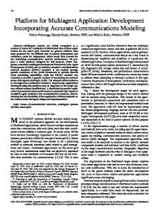
Fig. 1. FIPA agent management reference model, including the PEDA agents and the legacy systems the agents encapsulate.
mative framework within which FIPA agents exist and operate. It establishes the logical reference model for the creation, registration, location, communication, migration and retirement of agents.” The agent management reference model (see Fig. 1) includes two utility agents: the agent management service agent (AMS), which is compulsory, and the directory facilitator (DF) agent, which is optional. The AMS acts as a white pages, maintaining a directory of agents registered with the MAS. The DF acts as a yellow pages, maintaining a directory of agents and the services they can offer other agents. An agent can use the DF to search for other agents that can provide services that will aid it in fulfilling its own particular goals. In addition to the AMS and DF agents, PEDA comprises the following agents: • incident and event identification (IEI) agent that encapsulates the telemetry processor; • number of fault record retrieval (FRR) agents that interface with the FRR system used by SP PowerSystems; • fault record interpretation (FRI) agent that encapsulates the FRI expert system of the MBR toolset; • protection validation and diagnosis (PVD) agent that encapsulates the MBR toolset’s diagnostic engine; • collation agent that gathers information from the agents above and stores it in a relational database; • number of engineering assistant (EA) agents that engineers can configure to inform them of new diagnostic information as soon as it becomes available. The agents above were designed using the methodology described in [13]. The methodology offers a structured approach to designing MAS solutions that incorporate legacy systems. It involves defining the functional requirements of the system as a whole and then specifying the agents, agent interactions, and the ontology required to support those global functional requirements. The methodology supports the encapsulation of legacy systems as agents by identifying the additional function-
DAVIDSON et al.: APPLYING MULTI-AGENT SYSTEM TECHNOLOGY IN PRACTICE
563
TABLE I FIPA PERFORMATIVES USED BY PEDA
ality that must be implemented in order to encapsulate the existing intelligent systems as an autonomous intelligent agent. Use of the methodology results in a functional specification of each agent and the types of interaction it must support. Details of the methodology and its application to the case of PEDA can be found in [14]. B. Standards for Inter-Agent Communication PEDA agents communicate using the FIPA Agent Communication Language (ACL). ACL separates message structure from content. In the case of FIPA-ACL, a message contains 12 fields. The first field in the message is the “performative” field that defines the type of communicative act. FIPA specifies 22 performatives or communicative acts that define the type of message content and the flow of messages expected by each agent during a specific communicative act. Table I illustrates the main performatives employed by the PEDA agents and a summary of what the performative indicates about the content of the message. FIPA specifies formal models of the use of performatives in [26]. The content of a message comprises two parts: content language and ontology. The content language defines syntax, or grammar, of the content. The semantics or lexicon is drawn from the ontology. The content language and ontology employed are declared in the “content” and “ontology” fields of the message, respectively. FIPA has proposed standards for four different content languages: FIPA-Semantic Language (FIPA-SL); Knowledge Interchange Format (KIF); Resource Definition Framework (RDF); and Constraint Choice Language (CCL) [32]. In addition to the content languages above, other content languages, such as Description Logic (DL) [33], have found favor with some MAS developers. The choice of content language is important, as the chosen language will shape how a given ontology is expressed. In the case of PEDA, the FIPA-SL content language was used, simply because it was the only one of the four FIPA content language specification to reach a stable standard: KIF, RFD, and CCL are still experimental and liable to change. Although the FIPA-SL standard has been in existence since 1997, it only became a stable standard in 2002. The ontology used by PEDA was developed using an experimental version of FIPA-SL and had to be modified when the standard became stable [32], highlighting the problems that can be experienced when using an experimental standard.
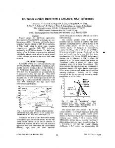
Fig. 2. PEDA agents use the FIPA subscription interaction to get information they require in order to fulfill their own goals.
Fig. 3. Using the telemetry processor, the IEI agent identifies an incident and informs all subscribed agents of the occurrence of the incident.
C. Agent Development Toolsets In the past decade, a number of different tools for developing multi-agent systems have become available [35]. The use of an agent development toolset can reduce the development time of a multi-agent system; however, the chosen toolset must display the robustness required for the application at hand. Importantly, systems implemented with different MAS toolsets, which comply with the same set of FIPA standards, should be able to interoperate. The version of PEDA installed at SP PowerSystems was implemented using the Java Agent Development Environment (JADE)[29]. JADE supports many of the current FIPA standards and provides: FIPA-compliant DF and AMS agents; parsers for a number of content languages, including FIPA-SL; and messaging functionality using FIPA-ACL. The following section illustrates how the PEDA agents interact in order to automate the management and analysis of SCADA and DFR data for SP PowerSystems. D. Agent Interactions The agent interaction diagrams in Figs. 2–4 illustrate the communicative steps the PEDA agents normally take in order to automate the post-fault analysis process (for the sake of
564
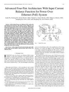
Fig. 4. Agent interactions initiated by the retrieval of a new fault record by one of the FRR agents.
clarity, only one FRR agent is shown on the interaction diagrams, whereas in reality, the PEDA agent community contains an FRR agent for each type of fault recorder utilized by SP PowerSystems. Similarly, PEDA supports the deployment of multiple engineering assistant agents; however, only one is shown in Figs. 2 and 3). When an agent joins the PEDA agent community, it must first register with the AMS and DF agents. As the agents are autonomous, they proactively search for other agents that can provide them with the data or information they require in order to carry out their own particular data analysis functions. As illustrated in Fig. 2, all agents subscribed to the IEI agent for incident information. The FRI subscribes to FRR for notification of new fault records. The PVD agent subscribes to the FRI agent for notification of newly interpreted fault records. When an incident occurs on the transmission network, e.g., a transient fault caused by lightning, the IEI agent identifies the incident from the SCADA data using the telemetry processor and informs all the agents that have subscribed to be informed of the identification of new incidents (see Fig. 3). The proactive nature of the agents means that each agent will seek out the data or information they can analyze relating to that incident. The prototype version of PEDA, reported in [14], was designed to prioritize the retrieval of fault records, as the digital fault records employed by SP PowerSystems at that time had a limited data storage capacity and, during a period of high activity on the network, the buffers of the fault recorders were being overwritten before the records could be retrieved. Since then, data storage units have been installed in substations removing the requirement for prioritized retrieval. Hence, additional agent interactions were added to allow the post-fault analysis process to be driven by the retrieval of new fault records. Fig. 4 illustrates the agent interactions that take place when a new fault record is retrieved. The FRR agent continually checks the fault recorder manufacturer’s proprietary fault record retrieval system for the retrieval of new records. When a new record is retrieved, the FRR agent sends a query-ref message to the IEI agent requesting the details of any incidents that occurred at the time the fault record was captured. The IEI agent
IEEE TRANSACTIONS ON POWER SYSTEMS, VOL. 21, NO. 2, MAY 2006
queries its internal incident archive and replies with an inform message that contains the details of all, if any, of the incidents that it identified as occurring at that time. Using this information, the FRR agent can then perform the first-cut classification of the fault record, as described in Section II. The FRR agent then informs all subscribed agents of the existence of the new record and its first-cut classification. The FRR agent informs the FRI and PVD agents of the existence of the new record. Once the FRI agent has interpreted the record, the PVD agent is informed of the existence of a new interpreted fault record. When the PVD agent has the interpreted fault records from all ends of the circuit, it performs its analysis and informs all subscribed agents of the existence of a new protection validation report. Before PEDA could be installed at SP PowerSystems, the effects of messaging on the corporate wide area network (WAN) had to be assessed, especially under storm conditions. During one of the last major storms in Scotland in January 2002, the transmission network experienced 166 incidents in 24 h where circuit protection operated (compared to only 66 of the same type of incident during the whole of 2003). Data captured during this storm were used as part of a case study to assess PEDA’s performance during extreme network conditions [14]. The majority of the incidents (134) occurred within a threeand-a-half–hour period, with never more than four incidents occurring at any given minute interval. After the identification of each incident, the IEI agent sends a single message, addressed to all subscribed agents, that contains the details of the incident. As each message is a few kilobytes in size at most, the effect of inter-agent messaging on the corporate WAN was assessed to be negligible. The retrieval of a fault record results in the interactions in Fig. 4. The rate of retrieval of fault records is limited by bandwidth of the modem connections to the substation. Again, the effect of inter-agent messaging was deemed to be negligible. E. Accessing the Results of PEDA’s Analysis Engineers access information derived by PEDA in one of two ways: by logging on to the PEDA intranet site using a standard web browser or by launching an EA agent. The collation agent (CA) gathers the information produced by the individual PEDA agents and archives it in a relational database. The database stores: incident information; all fault records and their first-cut classification; the results of the FRI agent’s analysis; and the protection validation reports produced by the PVD agent. A web server allows engineers to access information in the databases via the corporate intranet using a standard web browser. The intranet site for PEDA supports engineers by offering a list of incidents and the fault records relating to those incidents. Fault records can be downloaded via the intranet site, and the results of PVD and FRI agents can also be viewed. Engineers can also append any other relevant information relating to the incident. Alternatively, engineers can launch an EA agent on their desktop PC. The EA agent joins the PEDA community and can subscribe to information produced by the other PEDA agents. Engineers can configure the EA agent to subscribe for notification of the type of information they are interested in, depending on their role within the utility. The EA agent has
DAVIDSON et al.: APPLYING MULTI-AGENT SYSTEM TECHNOLOGY IN PRACTICE
565
the advantage that it allows engineers to be notified of the occurrence of an incident or the analysis of DFR data as soon as the information is available. VI. SYSTEM EXTENSIBILITY One of the motivations for the use of agents was to create an open and extensible post-fault analysis system, minimizing the impact of the addition of new data sources, analysis tools, and changes to the legacy systems employed. During the course of the PEDA’s development, the fault recorder manufacturer released an updated version of their software for retrieving and archiving fault records. The migration to the newer software involved upgrading the firmware within each fault recorder, which required a site visit, and resulted in the two versions of the manufacturer’s software running in parallel for several months, with DFR data stored in two separate archive databases running on separate PCs. SP PowerSystems currently employs three different types of fault recorder. When PEDA was initially installed at SP PowerSystems, the MAS contained three FRR agents, one for each type of recorder. Differences between the two versions of the fault record retrieval software meant that the FRR agents required updating in order to be compatible with the new version of the DFR manufacturer’s software. Three new FRR agents, one for each type of fault recorder, were developed and added to the MAS to deal with the retrieval of fault records from the updated fault record retrieval system. Although multiple FRR agents operate concurrently within the PEDA agent community, each agent has a different goal, i.e., the retrieval of records from a specific type of recorder. For several months, all six FRR agents were operating as part of the PEDA system. Once the migration between versions of the manufacturer’s fault record retrieval software was completed, the three original FRR agents were removed from the PEDA agent community. Adding and removing agents for a multi-agent system is trivial and can be achieved while other agents continue to operate. While adding new agents to the MAS is relatively simple, if data types change or new types of data are made available, then these changes must be reflected in the ontology. One of the effects of the software update was that the manufacturer’s fault record retrieval system now produces more detailed information on the cause of triggering of retrieved records. The ontology had to be extended to allow the new information to be passed between agents (see Fig. 5). As extending the ontology exploits inheritance and allows all the original terms of the ontology and their relationships to remain unchanged, the addition of the new terms only affects the agents that must understand them. In the case of the new type of fault record, only the collation agent required modification to cope with the new term. The example above demonstrates the flexibility and extensibility of the MAS approach: agents can be easily removed as hardware or legacy software becomes obsolete and added as new hardware or software is integrated into the monitoring system. VII. ONLINE TRIAL OF THE PEDA SYSTEM A. Results Since November 2004, PEDA’s IEI agent, a number of FRR agents, and a CA have been running online at SP PowerSystems, continually classifying and interpreting DFR and SCADA data. Table II shows the breakdown of incidents that were identified
Fig. 5. Extended section of the disturbance diagnosis ontology. The extensions are highlighted in grey. TABLE II BREAKDOWN OF INCIDENTS IDENTIFIED BY THE IEI AGENT
TABLE III BREAKDOWN OF FAULT RECORDS CLASSIFIED BY THE FRR AGENTS
during the six-month period between January and the end of June 2005. During this period, 2 million alarms were generated. The IEI agent correctly identified all 402 incidents that occurred in that period, classifying the incidents as illustrated in Table II. The six FRR agents retrieved a total of 583 records. Through collaboration with the IEI agent, the FRR agents were able to perform a first-cut classification based on the results of the analysis of the SCADA data. Table III illustrates the numbers of the different classification of fault records. B. Discussion of Results The results above illustrate that under normal operating conditions, such as the six-month period reported above, PEDA offers enhanced diagnostic support by automatically identifying the small percentage of records of most immediate interest to protection engineers. Using the PEDA intranet site, engineers have access to details of each incident, the results of the IEI agent’s analysis of the SCADA, and the details of all the fault records relating to the incident that can be downloaded via the corporate intranet within seconds of their retrieval from the site.
566
IEEE TRANSACTIONS ON POWER SYSTEMS, VOL. 21, NO. 2, MAY 2006
It is important to note that the performance of the individual agents is related to the efficacy of the underlying intelligent system they encapsulate. The IEI agent, for example, correctly identified all the incidents occurring during the online test. The FRR agents, which do not encapsulate a legacy intelligent system, are only able to perform the first-cut classification of the fault records through interaction with the IEI agent. The first-cut classification is aided by the fact that the fault records and SCADA alarms are GPS time-stamped, giving excellent correlation between the data sets. While PEDA provides day-to-day support to engineers by automating the post-fault analysis process, its ability to operate during storm conditions is also essential. Previous studies, carried out using historical data replayed in real time [14], have shown that PEDA agents are capable of dealing with the higher data rates experienced during a large-scale disturbance. Most importantly, the results represent six months of continual online operation of a MAS, implemented using the latest standards and tools, in a utility. This demonstrates that MAS technology can display the robustness required for use in the power industry. VIII. FUTURE WORK Currently, the authors are in the process of developing the FRI agent and PVD agent for “online” use at SP PowerSystems. As the PVD agent requires up-to-date knowledge of protection settings, we are working to integrate the PVD agent with SP PowerSystems’ IT systems for logging changes in protection and protection settings. It is envisaged that automated analysis of fault recorder data using model-based reasoning will be brought online within the next year. As this paper demonstrates, MAS technology allows the addition of new data sources and the removal of obsolete data sources. We plan to investigate the integration of circuit breaker condition monitoring systems within PEDA. The authors also intend to explore the interoperability of multi-agent systems by integrating PEDA with the Condition Monitoring Multi-agent System (COMMAS) [6] for the condition monitoring of transformers, to provide enhanced decision support based on a number of different types of power system data. IX. CONCLUSION While previous work has demonstrated the possibility of using multi-agent systems technology for the automation of the analysis of power systems data, in this paper, we have presented their experience of implementing such a system for deployment in the power industry. The results presented in this paper demonstrate that state-ofthe-art multi-agent system technology exhibits both the robustness and flexibility required for use within the power industry for the type of application described in this paper. While [2]–[10] illustrate the breadth of researchers in the field’s ambition for MAS technology, practical experience of the use of agents for applications in power engineering is lacking, and therefore, the use of agents by SP PowerSystems for management and analysis of SCADA and DFR data represents a significant step forward. The application of MAS
technology to real-time power system control applications, such as [7] and [10], will require a greater level of robustness than that required for automated post-fault analysis; however, results from the trials of the PEDA system should be seen as a positive indication that MAS technology is maturing to the point where the realization of a range of meaningful applications can be achieved. ACKNOWLEDGMENT The authors would like to thank F. McLeod and J. Hossack of SP PowerSystems and I. Broadfoot, V. Catterson, and G. Jahn of the Institute for Energy and Environment for their input into this research. REFERENCES [1] M. Wooldridge and N. R. Jennings, “Intelligent agents: Theory and practice,” Knowl. Eng. Rev., vol. 10, no. 2, pp. 115–152, 1995. [2] I. Praca, C. Ramos, Z. Vale, and M. Cordeiro, “MASCEM: A multiagent system that simulates competitive electricity markets,” IEEE Intell. Syst., vol. 18, no. 6, pp. 54–60, Nov.–Dec. 2003. [3] V. S. Koritarov, “Real-world market representation with agents,” IEEE Power Energy Mag., vol. 2, no. 4, pp. 39–46, Jul.–Aug. 2004. [4] T. Nagata and H. Sasaki, “A multi-agent approach to power system restoration,” IEEE Trans. Power Syst., vol. 17, no. 2, pp. 457–462, May 2002. [5] E. E. Mangina, S. D. J. McArthur, J. R. McDonald, and A. Moyes, “A multi agent system for monitoring industrial gas turbine start-up sequences,” IEEE Trans. Power Syst., vol. 16, no. 3, pp. 396–401, Aug. 2001. [6] S. D. J. McArthur, S. M. Strachan, and G. Jahn, “The design of a multiagent transformer condition monitoring system,” IEEE Trans. Power Syst., vol. 19, no. 4, pp. 1845–1852, Nov. 2004. [7] D. P. Buse, P. Sun, Q. H. Wu, and J. Fitch, “Agent-based substation automation,” IEEE Power Energy Mag., vol. 1, no. 2, pp. 50–55, Mar.–Apr. 2003. [8] Y. Tomita, C. Fukui, H. Kudo, J. Koda, and K. Yabe, “A cooperative protection system with an agent model,” IEEE Trans. Power Del., vol. 13, no. 4, pp. 1060–1066, Oct. 1998. [9] A. Dimeas and N. Hatziargyriou, “A multi-agent system for microgrids,” in Proc. IEEE Power Engineering Society General Meeting, Jun. 6–10, 2004, pp. 55–58. [10] C. C. Liu, J. Jung, G. T. Heydt, V. Vittal, and A. G. Phadke, “The strategic power infrastructure defense (SPID) system. A conceptual design,” IEEE Control Syst. Mag., vol. 20, no. 4, pp. 40–52, Aug. 2000. [11] M. Wooldridge and N. R. Jennings, “Pitfalls of agent oriented development,” in Proc. 2nd Int. Conf. Autonomous Agents, 1998, pp. 385–391. [12] S. D. J. McArthur, A. Dysko, J. R. McDonald, S. C. Bell, R. Mather, and M. S. Burt, “The application of model based reasoning within a decision support system for protection engineers,” IEEE Trans. Power Del., vol. 11, no. 4, pp. 1748–1754, Oct. 1996. [13] J. A. Hossack, J. Menal, S. D. J. McArthur, and J. R. McDonald, “A multiagent architecture for protection engineering diagnostic assistance,” IEEE Trans. Power Syst., vol. 18, no. 2, pp. 639–647, May 2003. [14] S. D. J. McArthur, J. R. McDonald, and J. A. Hossack, “A multi-agent approach to power system disturbance diagnosis,” in Autonomous Systems and Intelligent Agents in Power System Control and Operation (Power Systems), C. Rehtanz, Ed. New York: Springer-Verlag, 2003, pp. 75–99. [15] Z. A. Vale et al., “Better KBS for real-time applications in power system control centers: Experience from the SPARSE project,” Comput. Ind., vol. 37, pp. 97–111, 1998. [16] J. R. McDonald, G. M. Burt, and D. J. Young, “Alarm processing and fault diagnosis using knowledge-based systems for transmission and distribution network control,” IEEE Trans. Power Syst., vol. 7, no. 3, pp. 1292–1298, Aug. 1992. [17] M. Kezunovic, C. W. Fromen, and D. R. Sevcik, “An expert system for transmission substation event analysis,” IEEE Trans. Power Del., vol. 8, no. 4, pp. 1942–1949, Oct. 1993. [18] M. Kezonuvic and I. Rikalo, “Detect and classify faults using neural nets,” IEEE Comput. Appl. Power, vol. 9, no. 4, pp. 42–47, Oct. 1996. [19] P. Baroni, G. Lamperti, P. Pogliano, and M. Zanella, “Diagnosis of a class of distributed discrete-event systems,” IEEE Trans. Syst., Man, Cybern. A, Syst. Humans, vol. 3, no. 6, pp. 731–752, Nov. 2000.
DAVIDSON et al.: APPLYING MULTI-AGENT SYSTEM TECHNOLOGY IN PRACTICE
[20] M. Chantler, P. Pogliano, A. Aldea, G. Tornielli, T. Wyatt, and A. Jolley, “Use of fault-recorder data for diagnosing timing and other related faults in Electricity Transmission Networks,” IEEE Trans. Power Syst., vol. 15, no. 4, pp. 1388–1393, Nov. 2000. [21] E. M. Davidson, S. D. J. McArthur, and J. R. McDonald, “A toolset for applying model-based reasoning techniques to diagnostics for power systems protection,” IEEE Trans. Power Syst., vol. 18, no. 2, pp. 680–687, May 2003. , “Model-based reasoning techniques for the analysis of protection [22] operation,” in Proc. 12th Intelligent System Application Power Systems (ISAP) Conf., Lemnos, Greece, Aug. 2003. [23] A. Dysko, J. R. McDonald, G. M. Burt, J. Goody, and B. Gwyn, “Integrated modeling environment: A platform for dynamic protection modeling and advanced functionality,” in Proc. IEEE Transmission Distribution Conf., vol. 1, Apr. 11–16, 1999, pp. 406–411. [24] T. Wittig, N. R. Jennings, and E. M. Mandan, “ARCHON:—a framework for intelligent co-operations,” IEE-BCS J. Intell. Syst. Eng., vol. 3, no. 3, pp. 168–179, 1994. [25] Foundation for Intelligent Physical Agents (FIPA). (2002) FIPA ACL Message Structure Specification. [Online]. Available: http://fipa.org/ specs/fipa00061/SC00061G.html. [26] FIPA. (2002) FIPA Communicative Act Library Specification. [Online]. Available: http://www.fipa.org/specs/fipa00037/SC00037J.html. , (2002) FIPA Agent Management Specification. [Online]. Avail[27] able: http://www.fipa.org/specs/fipa00037/SC00037J.html. [28] Zeus Agent Toolkit. [Online]. Available: http://more.btexact.com/ projects/agents/zeus/. [29] Java Agent Development Framework (JADE). [Online]. Available: http://jade.cselt.it/. [30] A. F. Vojdani, “Tools for real-time business integration and collaboration,” IEEE Trans. Power Syst., vol. 18, no. 2, pp. 555–562, May 2003. [31] Common Information Model (CIM): CIM 10 Version, 1 001 976, EPRI, Palo Alto, CA, 2001. [32] FIPA. (2003) FIPA Content Language Specifications. [Online]. Available: http://fipa.org/repository/cls.php3. [33] A. Borgida, “Description logics in data management,” IEEE Trans. Knowl. Data Eng., vol. 7, no. 5, pp. 671–682, Oct. 1995. [34] E. M. Davidson, S. D. J. McArthur, J. R. McDonald, T. Cumming, and I. Watt, “Automating the analysis and management of power system data using multi-agent systems technology,” in Application and Innovations in Intelligent Systems XII (AI2004). New York: Springer-Verlag, 2004, pp. 151–164. [35] E. E. Mangina. Review of Software Products for Multi-Agent Systems. [Online] Available: http://www.agentlink.org.
567
Euan M. Davidson received the M.Eng. degree from the University of Strathclyde, Glasgow, U.K., in 2000. He is a Research Fellow with the Institute for Energy and Environment. His research interests include application of model-based reasoning, multi-agent systems, and other artificial intelligence techniques in power engineering.
Stephen D. J. McArthur (M’93) received the B.Eng. (Hons) and Ph.D. degrees from the University of Strathclyde, Glasgow, U.K., in 1992 and 1996, respectively. He is a Senior Lecturer with the Institute for Energy and Environment. His research interests include intelligent system applications in power engineering, condition monitoring, and multi-agent systems.
James R. McDonald (SM’98) received the B.Sc., M.Sc., and Ph.D. degrees from the University of Strathclyde, Glasgow, U.K., in 1978, 1984, and 1990, respectively. He holds the Rolls-Royce Chair in Power Engineering at the University of Strathclyde. He is Head of the Electronic and Electrical Engineering Department and Chairman of the Institute for Energy and Environment. He has published over 300 technical papers and two books.
Tom Cumming is an Engineer with SP PowerSystems, Motherwell, U.K., in their electrical transmission operations division.
Ian Watt is an engineer with SP PowerSystems, Motherwell, U.K., in their electrical transmission operations division.