2556
IEEE TRANSACTIONS ON POWER SYSTEMS, VOL. 26, NO. 4, NOVEMBER 2011
Dynamic State Estimation in Power System by Applying the Extended Kalman Filter With Unknown Inputs to Phasor Measurements Esmaeil Ghahremani and Innocent Kamwa, Fellow, IEEE
Abstract—Availability of the synchronous machine angle and speed variables give us an accurate picture of the overall condition of power networks leading therefore to an improved situational awareness by system operators. In addition, they would be essential in developing local and global control schemes aimed at enhancing system stability and reliability. In this paper, the extended Kalman filter (EKF) technique for dynamic state estimation of a synchronous machine using phasor measurement unit (PMU) quantities is developed. The simulation results of the EKF approach show the accuracy of the resulting state estimates. However, the traditional EKF method requires that all externally observed variables, including input signals, be measured or available, which may not always be the case. In synchronous machines, may not be available for example, the exciter output voltage for measuring in all cases. As a result, the extended Kalman filter with unknown inputs, referred to as EKF-UI, is proposed for identifying and estimating the states and the unknown inputs of the synchronous machine simultaneously. Simulation results demonstrate the efficiency and accuracy of the EKF-UI method under noisy or fault conditions, compared to the classic EKF approach and confirms its great potential in cases where there is no access to the input signals of the system. Index Terms—Dynamic state estimation, extended Kalman filtering, phasor measurements, power grid monitoring, power system operation, state estimation, synchronous generator.
I. INTRODUCTION N order to increase power system stability and reliability during and after disturbances, new strategies for enhancing operator situational awareness and power grid global and local controllers must be developed [1]–[3]. But high-performance monitoring and control schemes can hardly be built on the existing SCADA system which provides only steady, low-sampling density and nonsynchronous information about the network. SCADA measurements are too infrequent and nonsynchronous to capture information about the system dynamics. It is to remove these limitations that wide area measurements and control systems (WAMAC) using phasor measurement units
I
Manuscript received December 28, 2010; revised January 17, 2011 and March 14, 2011; accepted April 14, 2011. Date of publication June 09, 2011; date of current version October 21, 2011. Paper no. TPWRS-01044-2010. E. Ghahremani is with the Department of Electrical and Computer Engineering, Laval University, Québec City, QC G1V 0A6, Canada (e-mail: esmaeil.
[email protected]). I. Kamwa is with Hydro-Québec/IREQ, Power Systems and Mathematics, Varennes, QC J3X 1S1, Canada (e-mail:
[email protected]). Color versions of one or more of the figures in this paper are available online at http://ieeexplore.ieee.org. Digital Object Identifier 10.1109/TPWRS.2011.2145396
(PMUs) are being rapidly adopted worldwide. These systems enable synchronous power system dynamics to be monitored on a more refined time scale. Building on the ability of WAMAC systems to capture dynamic system information, the state estimators of a power system can generate dynamic states, e.g., generator rotor angles and generator speed, instead of (or in addition to) the static states of voltage magnitudes and phase angles [4]. From this point of view, this paper presents a dynamic state estimation process based on Kalman filtering techniques to estimate the dynamic states of the power system. A number of papers and studies have focused on just one dynamic state of the power system at a time, typically the rotor angle or speed which was estimated using artificial intelligence (AI) methods such as neural networks [5], [6]. These AI-based model-free estimators generate the estimated rotor angle or rotor speed signal without requiring a mathematical model or any machine parameters [5]. In the large-scale power system stability analysis, it is often preferable to have an exact model for all elements of the power network including lines, transformers, induction motors, FACTS, and also synchronous machines. Therefore, the physical model-based state estimator of the generator including voltage states in addition to rotor angle and speed would be more interesting in system monitoring and control. Use of the term “dynamic state estimation” can be traced back to the 1970s [7] when Kalman filtering techniques were first applied to improve the computational performance of the traditional steady-state estimation process in power system applications. Since then, there have been several studies in this area which have used different approaches to capture dynamic states of the power system [8]–[10]. However, very few papers on state estimators have set their focus on the synchronous generator which is at the heart of the power system. For example, a gain-scheduling scheme was used in [11] for state observer design in a single-machine infinite-bus (SMIB) system while constant voltages were assumed in the dynamic modeling, which significantly reduces the ability to represent the full dynamics of a power system. In [4], a dynamic state estimation method was proposed for the second-order synchronous machine which could be extended to a multi-machine system. The accuracy of the proposed method was examined in terms of measurement noise levels. But the problem lies in not including the field voltage dynamic equations in the second-order system model of a synchronous machine. Also reported in [12] is dynamic state estimation scheme for a sixth-order power system with a third order for synchronous machine. However, they assumed
0885-8950/$26.00 © 2011 IEEE
GHAHREMANI AND KAMWA: DYNAMIC STATE ESTIMATION IN POWER SYSTEM
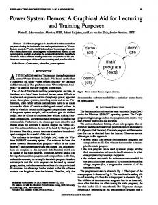
the exciter output voltage and rotor angle to be two measurable signals, following on this respect, other papers in this area [13]. More specifically, the latter proposed a parameter estimation procedure based on the unscented Kalman filter (UKF) was presented for the third-order model of a synchronous genas one of the states with erator assuming the output power the and the constant as input signals of the machine [13]. A third-order model was also assumed in [14] and approximate algebraic equilibrium equations were used to derive the quasi-steady states of the generator, assuming the field current was available in addition to the terminal quantities. A methodology for real-time dynamic monitoring of the electric power systems using optimal state estimators is presented in [15], whereby the system state vector is extended to include generator internal dynamic states (rotor speed and angle ), in addition to algebraic states (e.g., terminal voltage, generator internal voltage, output electric power, and so on). The measurement set in [15] consists of and (both with magnitude and phase), , , and the generator speed and acceleration (frequency and rate of change of frequency at the substation). In [16], the measurement set also includes the generator speed and acceleration like [15] while for the modeling of the generator, the authors proposed a physically based generator model. The presented model was expressed in terms of the actual self and mutual inductances of the generator windings as a function of rotor position. In contrast with the above approaches, this paper proposed a dynamic state estimator method based on extended Kalman filtering (EKF) applied to signals obtained from a PMU which is assumed to be installed in the substation of a power plant. The synchronous machine model is a fourth-order, nonlinear state-space model with , , and as inputs and and as outputs. In situations where the signal is not accessible for measuring, a novel method is proposed based on extended Kalman filtering with unknown inputs (EKF-UI). From experimental test considerations, it could become a critical factor since measuring the field current and voltage is not easily applicable to brushless excitation systems. In any event, it will involve additional wiring and labor costs using existing technologies. This paper is organized as follows. The fourth-order nonlinear model structure considered for modeling the synchronous machine is given in Section II. In Section III, assuming that the signal is accessible, dynamic state estimation of the power system will be presented using the EKF method. Section IV includes an extended version of EKF, the EKF-UI method for an inaccessible or unknown signal. To demonstrate the robustness of the EKF-UI method, detailed simulation studies are presented in Section V. Section VI discusses the findings and Section VII concludes the paper. II. SINGLE-MACHINE INFINITE-BUS POWER SYSTEM A general power system configuration can be simplified to an equivalent circuit system with a single machine connected to an infinite bus via transmission lines [1]. The so-called singlemachine infinite-bus (SMIB) system, shown in Fig. 1, will be the basis for developing and validating our generator state estimator. Assuming a classical synchronous generator model, let define as the angle by which , the q-axis component of the
2557
Fig. 1. Synchronous machine connected to an infinite bus via transmission lines.
voltage behind transient reactance , leads the terminal bus (or ). If the terminal voltage chosen as the reference phasor, the generator in Fig. 1 can then be represented in the dqo domain by the following fourth-order nonlinear equation:
(1)
where is the nominal synchronous speed (elec. the mechanical input torque rad/s), the rotor speed (pu), (pu), the air-gap torque or electrical output power (pu), the exciter output voltage or the field voltage as seen from the armature (pu), and the rotor angle in (elec.rad). Other variables and constants are defined in Table I in the Appendix. Based on the phasor diagram associated to the network of Fig. 1, the air-gap torque will be equal to the terminal electrical power (or ) neglecting the stator resistance : (2) where the d-and q-axis voltages
can be expressed as (3)
Also, the d-axis and q-axis currents
are
(4)
Replacing and
by the state variables
and
, we obtain (5)
Using (3) and (5) in (2) and after some mathematical simplification, the electrical output power at terminal bus with the state variables and can be obtained as (6) To summarize, using (6) and (5) in (1), the fourth-order nonlinear synchronous machine state space model is rewritten as
2558
IEEE TRANSACTIONS ON POWER SYSTEMS, VOL. 26, NO. 4, NOVEMBER 2011
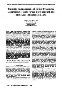
(1). This assumption may be defendable for machines on which the field voltage is accessible or for the next generation of synchronous machines with embedded smart sensors. But in cases signal is not available or measurable, the new exwhere the tended version of EKF known as the EKF-UI will be employed. III. EXTENDED KALMAN FILTER (EKF) METHOD A. EKF Algorithm Description To derive the discrete-time EKF algorithm, we start from the basic definition of time derivation of a variable : Fig. 2. Overview of the dynamic state estimator for a synchronous machine.
(9) is the time step, and indicate the time at and , respectively. Replacing (8) in (9), we easily obtain (10) and (11) below:
where (7), shown at the bottom of the page, in a form suitable for state estimation purposes, with the electrical output power as the single measurable system output, where all the parameters and quantities other than state variables are (or assumed to be) known and measurable. We can therefore represent (7) in a global structure as (8): (8) where is the state variable vector defined in (1), the process (state) noise, the measurement noise, the system function, the output function, and the measurable output. After replacing the quantities , , and with the (5) and (6), which include the terminal voltage , it appears that the vector in (1) now needs to be modified in order to add as third input as (7). Therefore, will have in (8) the vector defined as . In the nonlinear state space model (7), the terminal bus signals , , and are accessible from a PMU device which is assumed to be installed at the generator terminal bus. The PMU is a power system device that samples input voltage and current waveforms using a common synchronizing signal from the GPS and calculates the phasors (magnitude and angle) using the discrete Fourier transform (DFT) [17]. The overall plan of the estimation process is illustrated in Fig. 2. The dotted line of shows that one of the approaches in this paper, the EKF-UI state estimator, does not need the signal which is estimated with the states. The classic EKF-based state estimator will first be developed for the case where the signal is measurable and used as the second exogenous input in
(10) (11) If rewritten properly, (11) gives us the discrete-time system equations presented in (12): (12) where is the system state vector, is the known input vector is either the process (random state) noise or of the system, represents inaccuracies in the system model, is the noisy observation or measured variable (output) vector, and is the measurement noise. It is assumed that measurements are made at by the PMUs, at discrete sampling time instants . The noises sequences and are supposed to be white, Gaussian, and independent of each other: (13) (14) (15) (16) Equations (13) and (14) imply that and have a zero mean, with covariance matrices and , respectively. Equa-
(7)
GHAHREMANI AND KAMWA: DYNAMIC STATE ESTIMATION IN POWER SYSTEM
2559
tion (15) implies that the values of (respectively, ), at different times instants, are not correlated while equation (16) shows that the process (state) and measurement (observation) noises are not cross-correlated [18]. Starting from these initial considerations, the discrete-time EKF algorithm for the state estimation process consists of two steps [18]: Step I) Initialization of the filter at : (17) where indicates the expected value and the in superscript denotes that the estimate is an a posteriori estimate. Step II) For perform the following: a) Compute the following partial-derivation matrices: (18) b) Perform the time update of the state estimate and estimation-error co-variance as follows:
(19) c) Compute the following partial-derivative matrices: (20) d) Perform the measurement update of the state estimate and estimation-error covariance as follows: Fig. 3. EKF state estimation results with noise. (a) Estimated states. (b) Estimated output.
(21) B. EKF Method Simulation Results The discrete-time EKF algorithm has been implemented in Matlab/Simulink using the embedded function programming feature of Simulink. The simulation of the generator nonlinear model is performed while including saturation assuming a twofactor d-q saturation model [1], [2], with the parameters presented in Table I in the Appendix. On the other hand, the EKFbased estimation of the dynamic states is carried out in parallel with the simulation, in a single run without any assumption about saturation of the underlying generator. In the embedded , , and and the Matlab function block, the signals system observation signal (as ) are used as inputs for the EKF. The EKF block has access to the values of these signals ( , , , and ) and known machine parameters at each iteration. The embedded block then generates the state estimate based on its inside algorithm which is described in the previous section, while using the time step set through the Simulink configuration panel . The initial values for states and state covariance matrix are and . Also, the process and measurement noise covariance matrices are set as and
. The size of vector arises from the fact that there are four states. For simulation near real system conditions, white-noise sequences with covariance and were added to the state process and output measurement, respectively. Under these conditions, the EKF states estimates are presented in Fig. 3(a). The estimated output signal compared with the real output signal is shown in Fig. 3(b). To save space, we will present just the results in the presence of noise. It is obvious that accurate and nearly perfect state and output estimates results were obtained for the system without noise. IV. EXTENDED KALMAN FILTER WITH UNKNOWN INPUTS (EKF-UI) METHOD A. EKF-UI Method Background The EKF method of the previous section requires that both the deterministic inputs in the model and the measurement equations be known, which sometimes may not be the case in reality. The presence of unknown inputs could severely restrict the performance of classical nonlinear filters since a high bias will be introduced into the state estimation due to uncertainties from the unknown inputs. On the other hand, it is not always appropriate
2560
IEEE TRANSACTIONS ON POWER SYSTEMS, VOL. 26, NO. 4, NOVEMBER 2011
to treat unknown inputs as random noise to fit those traditional nonlinear filter approaches because 1) the unknown inputs could be signals with an arbitrary type and magnitude so it is not acceptable to assume them to be stationary and zero-mean random noise; and 2) some unknown inputs need to be estimated for process control and optimization purposes. In this regard, joint estimation of the states and unknown inputs for nonlinear stochastic systems becomes a meaningful task [19], which is often addressed as a constrained optimization problem [20], [21] where the state unbiasedness is the constraint and a joint global optimization of states and unknown inputs cannot be guaranteed [20]. To avoid the shortcomings of those approaches, an EKF-UI [22] was proposed in the field of civil engineering for earthquake damage estimation studies. Its major novelty is that the unknown inputs are regarded as part of the states instead of disturbances (see [20] and [21]). As a result, the EKF-UI approach can be directly derived from the unconstrained objective function of the traditional EKF (weighted least-squares objective function) and thus becomes a more general version of EKF. Since no prior information about unknown inputs is required, the proposed EKF-UI is quite suitable for the state estimation of a nonlinear system in the presence of unknown inputs. Therefore, it could be employed in state estiinput mation of a synchronous machine with the unknown signal.
where (25) (26)
(27)
(28) (29) The estimates and can be determined by minimizing the objective function of the summed square error as follows: between and (30) is a weighting matrix defined as the where inverse of the covariance matrix for model and measurement is a p-output error vector at noise; , and is a pk-vector [19], [22]. By minimizing with respect to the unknown extended state vector (subscript “e” denotes extended):
B. EKF-UI Algorithm Description An analytical solution for the proposed EKF-UI approach derived and presented in [22] for earthquake damage estimation studies will be modified and applied here based on the nonlinear synchronous machine system. This proposed EKF-UI technique [19] is applicable to both linear and nonlinear structures. Let the continuous-time nonlinear system (8) be represented in the discrete domain by the following (22), in which the subscripts and indicate time instants and respectively:
(31) to obtain the least-squares estimation (LSE) of at and by taking the partial derivative of with respect to and setting it equal to zero at ; we will have as (32) and in turn (33): (32)
(33) (22) where denotes an n-dimensional nonlinear system function; , a p-dimensional output function; and are the n-state vector of the system; and are s-known input vectors; is the r-unknown input vector; is the p-observation (measured) output vector; and are n-model noise (uncertainty) and p-measurement noise vectors assumed to be mutually independent Gaussian white with the same characteristic presented in (13)–(16). Based on the above system, the EKF-UI approach can be used to estimate unknown state and at given and unknown input vectors the observation denoted as and , respectively. The derivations of the system which are essential for the EKF-UI method [19], [22] are briefly explained below from (23)–(29):
(23) (24)
is a [pk] known vector and is a known matrix. After some algebra, the recursive solution for and is obtained by the following steps [19], [22]: Step 0) Initialization of the filter at where
(34)
is a gain factor for the unknown input. where Step I) Prediction (35) and are the estimation of states where . and unknown inputs at Step II) Gain Computation The computation at of the gain matrix for estimation of the states and for the estimation of unknown input is
GHAHREMANI AND KAMWA: DYNAMIC STATE ESTIMATION IN POWER SYSTEM
given by (36) and (37), as shown at the bottom of the page. , we will have In (36) for the gain matrix
2561
outputs. Similarly the active power equation, the reactive power with the state variables and equation, can be derived as (42):
(38) and is the autocovariance function of the model . noise process vector Step III) Update In this step, the estimation of state and unknown inputs at , , and is updated from the combination of the state prediction and current measurement by (39) and (40), respectively, the latter of which is at the bottom of the page: (39) in (38) is updated at The covariance matrix using (41), which is shown at the bottom of the , , and can be calculated page. , respectively [19], from (36)–(38) by replacing by [22]. Note that by checking the existence condition for in (32), it can be concluded that the major restriction of EKF-UI is that the number of output measurements (p) should be larger than the number of unknown inputs (r). Based on this and because our system has just one unknown input, we need to add a new output from possible candidates accessible from PMU measurements not yet involved . Since we have chosen to compute in the EKF-UI: and the gradients in (18), (20), and also in (27)–(29) analytically, as presented in the Appendix, using as the second output would require an appropriate and explicit equation of with respect to the states and inputs to be able to compute its gradient for matrix. By replacing (5) in (4), it appears that such an equation for with respect to the states and inputs would be highly nonlinear and time consuming for analytical gradient calculation. Therefore, the reactive power of synchronous machine has been added to the active power for a total of two system
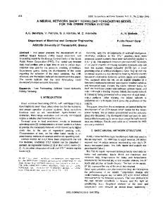
(42) Thus, with the greater number of system outputs than the number of unknown inputs , we can implement the described EKF-UI on the fourth-order synchronous generator model. C. EKF-UI Method Simulation Results The EKF-UI algorithm was developed in Simulink using the embedded function block, just as we did for the EKF method. was the only measurable output signal In the latter case, and , , and were the three input signals. But in the and are the two output measurements EKF-UI method, and the input signals and are still necessary. The input is now assumed to be inaccessible or unknown. The iniand for the gain tial values vector for states is factor matrix is . The initial values related to the unknown input are: and . Also, the mean and covariance of the state and output noise matrices are as: and . To better reflect real system conditions, white noise was added to the state with (mean, covariance) and to the measured output with (mean, covariance) . Under these assumptions, the results of the EKF-UI algorithm for online state estimation of the fourthorder nonlinear model of the synchronous generator subjected to a step on are presented in Fig. 4(a). The estimated output signals and the unknown input estimate are also shown in Fig. 4(b) and (c), respectively. The results obtained for the system without noise were even better than Fig. 4, achieving a match near to perfect between EKF-UI estimates and theoretical values.
(36)
(37)
(40)
(41)
2562
IEEE TRANSACTIONS ON POWER SYSTEMS, VOL. 26, NO. 4, NOVEMBER 2011
state estimation process will be performed assuming that is a ramp signal. The EKF-UI performance under network fault disturbances will also be analyzed. A.
Input Signal: Ramp
In the simulations of this section, all settings including the initial values, time steps, and noise characteristics are the same as in the previous section, except that we replaced the step with a ramp signal having a . The simulation results for the ramp signal are illustrated in Fig. 5. They confirm that the proposed method is capable of tracking a timevariant unknown input, while estimating the states correctly. Again to save space, we present in Fig. 5 the first and third states only. B. Fault Analysis: Middle-Line Short Circuit Fault Based on the equivalent circuit in Fig. 1, network disturbances impacts on the EKF-UI state estimator is studied by applying a short-circuit contingency at the mid-point of the . The fault analysis relied on transmission line at the fourth-order synchronous machine described in Section II. The synchronous machine model used in the fault simulation includes a two-factor saturation model with the parameters given in Table I in the Appendix. The analysis will be based on two post-disturbance scenarios: 1) stable and 2) unstable. For the first scenario, the fault is cleared after 0.1 (s) at and the system remained stable. The Simulink SMIB model settings and estimator initial values are the same as in Sections IV and V studies, except that we removed the noise in order to have clarity in the results and be able to track the performance of the state estimator at the time of fault occurrence. For this reason, we show the first 4 s after the fault only. The results in the stable case are presented in Fig. 6. To save space, a single output estimate, and two states (first and third) are presented. From these results, it is clear that the EKF-UI estimator generates the correct estimates under network fault disturbance. However, attentive verification of the fault time-period revealed that, just after the fault occurrence, the estimator produces discontinuous responses and will track the actual outputs only after fault clearing. In the second scenario, the fault was cleared after 0.3 (s) only, at , and the system therefore went into an unstable condition. Like for the stable case, the state estimator generated the estimated states with appropriate accuracy as shown in Fig. 7. Based on these two scenarios, we conclude that the EKF-UI approach is capable of estimating the dynamic state of the power system independently of the stability condition. Also when the fault simulations were repeated with the noise added of the same magnitudes as in Fig. 4, the results were satisfactory, similar to Figs. 6 and 7 in terms of accuracy. VI. DISCUSSION Fig. 4. EKF-UI state estimation results with noise. (a) Estimated states. (b) Estimated outputs. (c) Estimated unknown input and the error.
V. ROBUSTNESS CHECKING OF THE EKF-UI METHOD For checking the effectiveness and robustness of the EKF-UI method, especially under time variant unknown input, the
By comparing the initial values of the states in the EKF method and the EKF-UI method , it is noticed that the latter is more robust against a poor initial value of the rotor angle than the EKF method, for which we cannot set far from the nominal rotor angle.
GHAHREMANI AND KAMWA: DYNAMIC STATE ESTIMATION IN POWER SYSTEM
2563
Fig. 6. EKF-UI state estimation results in stable short-circuit fault. (a) Estimated states. (b) Estimated output. (c) Estimated unknown input.
= Constant
=
Fig. 5. EKF-UI state estimation results with T m and E f d . (a) Estimated states. (b) Estimated outputs. (c) Estimated unknown input.
Ramp
Noticing in Figs. 6 and 7 that some state estimates are wrong during the fault, it could make sense to block the slow-changing states at their pre-fault values during the fault, in order to reduce the discontinuity-induced errors. The simulation studies were
repeated for different sets of machine and external system parameters to verify the EKF-UI method capability with respect to different sets of parameters and to analyze the influence of changing parameters on the proposed method. As expected, we obtained acceptable results in the simulations when we had different test machines (such as salient versus round rotor) and external systems with varying reactance. Lastly we performed additional simulation studies at different operating points considering saturation factors, in order to check the accuracy of the proposed EKF-UI method while varying the synchronous machine operating point. In all these sets of simulations, we again obtained accurate estimation of the states, outputs, and unknown input.
2564
IEEE TRANSACTIONS ON POWER SYSTEMS, VOL. 26, NO. 4, NOVEMBER 2011
and , which are now available through the Based on EKF-UI method estimation results, the value of and in turn can be estimated. Then using the field current estimated as above and assuming and to be known (including eventually the impact of a saturation model), the following equations can be derived [1]:
(45) where is the synchronous reactance, is the terminal voltage, and is the field current. The equations in (45) can be used to estimate one part of capability curve which is known as field current heating limit [1]. VII. CONCLUSION In this paper, two different approaches were presented for dynamic state estimation of a power system including the synchronous generator rotor angle and rotor speed. The first approach was the traditional nonlinear state estimator, the EKF method, which includes linearization steps in its algorithm. Simulation results of the EKF estimator showed appropriate accuracy in estimating the dynamic states of a saturated fourth-order generator connected to an infinite bus, under noisy processes and measurements. However, the EKF method requires that all input data be measured or available, which may not be the case in some configurations (e.g., with brushless exciters) where the is not easily measured from the power plant field voltage control room. The EKF-UI was consequently proposed for addressing this issue. We implemented it to simultaneously estimate the states of the system and the unknown input voltage . The robustness and effectiveness of the proposed EKF-UI approach was checked by successfully applying it to various kinds of field voltage and mechanical torque inputs, ranging from step to ramp signals. The developed EKF-based estimators were effective as well under network fault conditions with process and measurement noise included.
APPENDIX Fig. 7. EKF-UI state estimation results in unstable short-circuit fault. (a) Estimated states. (b) Estimated output. (c) Estimated unknown input.
Another interesting result, based on the estimated states of synchronous machine, would consist to estimate the capability curve of machine. First, let us define the internal generator voltage, , as the voltage proportional to the field current :
Definitions of Variables and Constants: The main variables and constants of the system presented in (1)–(7) and their values in p.u are expressed in Table I. “No.” in the table means nominal (or initial) value. Gradient Calculation in the EKF and EKF-UI Methods: The gradients in (18), (20), and also in (27)–(29) are computed analytically. We now show the mathematical procedure of the calculations. By using (8) in (27) to compute the gradient matrix , we will have (46) and in turn (47):
(43) Then, the relation between can be expressed as
and third state of machine (46) (44)
(47)
GHAHREMANI AND KAMWA: DYNAMIC STATE ESTIMATION IN POWER SYSTEM
2565
is zero . Also, for the third while the value of state equation, the elements of the matrix with and can be calculated as (50):
TABLE I VARIABLES AND CONSTANTS DEFINITIONS
(50) and finally, for the fourth state equation, we will have
(51) and therefore, taking the first state equation from (7), the elements [ and ] can be calculated as (48):
, while the values of and are all zero. For calculating the matrix in (29), we could do the same as we did for , except that in the output matrix, we do not have the factor in the discrete form of the equations. So, we can easily calculate the gradients based on the main equations in (7) and (8). From (8), the output equation of the system is (52)
(48)
and for calculating
from (7), Similarly, using the second state equation some other elements of matrix can be calculated as (49):
(53)
Replacing gradient matrix
(49)
in (29), we will have
from (7) in (49), the first row of the can be calculated as (54):
(54)
2566
IEEE TRANSACTIONS ON POWER SYSTEMS, VOL. 26, NO. 4, NOVEMBER 2011
Similarly, we could compute the second-row elements of the matrix by substituting (42) in (52) to obtain and as follows in (55):
(55) Finally, using the state equations from (7) for calculating the in (28), the elements of the matrix can be matrix computed as follows:
[9] G. Valverde and V. Terzija, “Unscented Kalman filter for power system dynamic state estimation,” IET Gen., Transm., Distrib., vol. 5, no. 1, pp. 29–37, 2011. [10] K. R. Shih and S. J. Huang, “Application of a robust algorithm for dynamic state estimation of a power system,” IEEE Trans. Power Syst., vol. 17, no. 1, pp. 141–147, Feb. 2002. [11] J. Chang, G. N. Taranto, and J. Chow, “Dynamic state estimation in power system using gain-scheduled nonlinear observer,” in Proc. 1995 IEEE Control Application Conf, pp. 221–226. [12] L. Lin, Linawati, L. Jasa, and E. Ambikairajah, “A hybrid state estimation scheme for power system,” in Proc. 2002 IEEE Circuits and Systems Conf. (APCCAS’02), vol. 1, pp. 555–558. [13] M. Huanga, W. Li, and W. Yana, “Estimating parameters of synchronous generators using square-root unscented Kalman filter,” Int. J. Elect. Power Syst. Res., vol. 80, pp. 1137–1144, Sep. 2010. [14] V. Venkatasubramanian and R. G. Kavasseri, “Direct computation of generator internal dynamic states from terminal measurements,” in Proc. 37th Hawaii Int. Conf. System Sciences, 2004, pp. 1–6. [15] E. Farantatos, G. K. Stefopoulos, G. J. Cokkinides, and A. P. Meliopoulos, “PMU-based dynamic state estimation electric power systems,” in Proc. 2009 Power & Energy Society Meeting (PES2009), pp. 1–8. [16] S. Meliopoulos, G. Cokkinides, R. Huang, E. Farantatos, S. Choi, and Y. Lee, “Wide area dynamic monitoring and stability controls,” in Proc. 2010 Bulk Power System Dynamic and Control, Brazil, Aug. 1–6, 2010. [17] I. Kamwa, M. Leclerc, and D. McNabb, “Performance of demodulation-based frequency measurement algorithms used in typical PMUs,” IEEE Trans. Power Del., vol. 19, no. 2, pp. 505–514, Apr. 2004. and Nonlinear Ap[18] D. Simon, Optimal State Estimation; Kalman, proaches. Hoboken, NJ: Wiley, 2006. [19] S. Pan, H. Su, P. Li, and Y. Gu, “State estimation for batch distillation operation with a novel extended Kalman filter approach,” in Proc. 48th Conf. Decision and Control, China, 2009, pp. 1884–1889. [20] S. Gillijns and B. De Moor, “Unbiased minimum-variance input and state estimation for linear discrete-time systems,” Automatica, vol. 33, no. 4, pp. 111–116, 2007. [21] Y. Cheng, H. Ye, Y. Wang, and D. Zhou, “Unbiased minimum-variance state estimation for linear systems with unknown input,” Automatica, vol. 45, no. 2, pp. 485–491, 2009. [22] J. N. Yang, S. Pan, and H. Huang, “An adaptive extended Kalman filter for structural damage identification II: Unknown inputs,” Int. J. Structure Control Health Monitor., vol. 14, no. 13, pp. 497–521, Apr. 2007.
H
(56) vector in (56) which is related to the unknown The input estimation has just a single nonzero element. We have just one unknown input and it is in the third equation of the system. ACKNOWLEDGMENT The authors would like to thank Prof. J. N. Yang and his group, especially Dr. S. Pan, for their seminal papers [19], [22] investigating the extended Kalman filter with unknown inputs, in the fields of civil engineering (earthquake damage estimation) and chemical process engineering. Their findings showed us the path for a new approach to jointly estimate the field voltage and states of the synchronous generator. REFERENCES [1] P. Kundur, Power System Stability and Control. New York: McGraw Hill, 1994. [2] Y. N. Yu, Electric Power System Dynamic. New York: Academic, 1983. [3] M. Anjia, Y. Jiaxi, and G. Zhizhong, “PMU placement and data processing in WAMS that complement SCADA,” in Proc. 2005 IEEE/PES General Meeting, pp. 780–783. [4] Z. Huang, K. Schneider, and J. Neplocha, “Feasibility studies of applying Kalman filter techniques to power system dynamic state estimation,” in Proc. 2007 Int. Power Engineering Conf. (IPEC), pp. 376–382. [5] I. Kamwa, B. Baraboi, and R. Wamkeue, “Sensorless ANN-based speed estimation of synchronous generator: Improved performance through physically motivated pre-filters,” in Proc. 2006 IEEE Neural Network Conf. (IJCNN), pp. 1710–1718. [6] A. De Angel, P. Geurts, D. Ernst, M. Glavic, and L. Wehenkel, “Estimation of rotor angle of synchronous machines using artificial neural networks and local PMU-based quantities,” ELSEVIER Neurocomput., vol. 70, pp. 2668–2678, Oct. 2007. [7] A. S. Debs and R. E. Larson, “A dynamic estimation for tracking the state of a power system,” IEEE Trans. Power App. Syst., vol. PAS-89, pp. 1670–1678, Sep.–Oct. 1970. [8] J. K. Mandal, A. K. Sinha, and L. Roy, “Incorporating nonlinearity of measurement function in power system dynamic state estimation,” Proc. Inst. Elect. Eng., Gen., Transm., Distrib., vol. 142, no. 3, pp. 289–296, May 1995.
Esmaeil Ghahremani received the B.Sc. and M.Sc. degrees from Amirkabir University of Technology (Tehran Polytechnic), Tehran, Iran, in 2003 and 2007, respectively. He has been pursuing the Ph.D. degree under Prof. Kamwa’s supervision, studying in power systems stability area, at Laval University, Québec City, QC, Canada, since 2008. His research interests include power system stability studies, dynamic state estimation of power system, FACTS placement, and wide area control of power system.
Innocent Kamwa (S’83–M’88–SM’98–F’05) received the Ph.D. degree in electrical engineering from Laval University, Québec City, QC, Canada, in 1988. Since then, he has been with the Hydro-Québec Research Institute (IREQ), Power System Analysis, Operation and Control, Varennes, QC, where he is currently a Principal Researcher in bulk system dynamic performance. He has been an Associate Professor of electrical engineering at Laval University since 1990. Dr. Kamwa has been active for the last 13 years on the IEEE Electric Machinery Committee, where he is presently the Standards Coordinator. A member of CIGRÉ and a registered professional engineer, he is a recipient of the 1998, 2003, and 2009 IEEE Power Engineering Society Prize Paper Awards and is currently serving on the Adcom of the IEEE System Dynamic Performance Committee.