SysCon 2008 – IEEE International Systems Conference Montreal, Canada, April 7–10, 2008
Applying Object Oriented Systems Engineering to Complex Systems Robert Cloutier1, Regina Griego2 1
School of Systems and Enterprises, Stevens Institute of Technology, Hoboken, NJ 07030,
[email protected] 2 Sandia National Laboratories, Albuquerque, NM,
[email protected] . Abstract – Analyzing systems using functional analysis has been the mainstream for Systems Engineering for five decades. With the advent of object oriented software methods and the Object Management Group’s (OMG) Unified Modeling Language™ (UML), a number of Systems Engineers working on software intensive systems began to apply Use Cases and Object Oriented Analysis and Design (OOAD) methods to large scale, complex systems. While the use of these OO methods is still controversial within the systems engineering community, many systems engineers that apply OO methods effectively have used functional analysis and understand the strengths of both methods. One challenge systems engineer’s face when applying OO methods to the early phases of engineering is that most experienced users of UML define and design the solution, not to develop the concept. Therefore, published examples of UML/SysML usage tend to be at the implementation level instead at the much higher abstract level of problem definition and concept development. However, defining the concept and developing the initial semantics in a tool other than PowerPoint or Visio can set the tone for the entire project and drive the success of the entire engineering effort. Additionally, UML/SysML offers an extended and connected set of diagrams that allow one to better explore the operational scenarios and system design, and their related semantics. FireSAT is a well known fictitious system of systems space mission to provide a space based approach to wildfire detection, monitor and control. This paper will explore the use of OOAD methods to FireSAT for problem definition, concept development, and system architecture development. Using the OMG’s recently adopted System Modeling Language™ (SysML) and more traditional Systems engineering modeling techniques, this paper will compare and contrast some of the differences between OO and functional methods, showing diagrams from each approach.
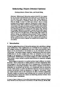
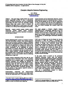
2) Provide continuous monitoring of high priority and potentially dangerous wildfires 3) Reduce the economic impact of wildfires 4) Reduce the risk to firefighting personnel 5) Develop an integrated ground, air and space architecture to detect and monitor wildfires in the U.S. 6) Collect statistical data on the outbreak, spread, speed, and duration of wildfires 7) Detect and monitor wildfires in other countries 8) Collect other forest management data 9) Demonstrate to the public that positive action is underway to contain wildfires Beyond this, there was no discussion or justification as to how the government or contractor arrived at that need statement or definition of goals. Using their engineering processes, they decided the CONOPS (Figure 1) and System of Systems (SoS) Architecture (Figure 2) on which they based all further FireSAT design and implementation.
Keywords – OOSE, concept development, system architecture, SysML
I.
INTRODUCTION
FireSAT case study was introduced in 1998 by Larson & Wertz [1] and was intended to be an exercise for space engineering students. The FireSAT mission was based on the assumption that NASA and the US Forest Service requested a study be performed to investigate the feasibility of developing the mission concept for an on orbit fire detection system. The stated system need, as presented in the case study stated: The United States needs a more effective means to detect and monitor potentially dangerous wildfires. The FireSAT mission had the following goals identified: 1) Provide timely detection of potentially dangerous wildfires
Figure 1 - Original FireSAT CONOPS Diagram 0 FireSAT Mission Architecture System of Systems
1
2
3
4
5
Orbits & Trajectory Element
Space Element
Launch Element
Mission Operations Element
Subject Element (Wildfires)
Environment
Element
Element
Element
Element
Figure 2 - Original FireSAT System of System Architecture
The remainder of this paper will propose an object oriented approach and use of SysML to document an alternative architecture that appears to be more flexible and able to evolve as the FireSAT mission evolves. II. APPROACH When investigating the SCADA example of FireSAT it was clear that a standard Functional approach was taken. What may not have been as clear to engineers is that the approach taken started with a solution in mind and no discussions was focused on describing the problem or completing an analysis of the stakeholders and documenting the context of the problem. This oversight is common when developing systems. The intent of this paper is to systematically apply a Systems Engineering approach by first fully describing the problem using a rigorous approach and SysML. The steps in the process are: 1) State the problem 2) Identify and profile stakeholders 3) Analyze stakeholder functional viewpoint 4) Model stakeholder interaction 5) Determine goals of the stakeholders or stakeholder classes 6) Analyze goals and create a Use Case Architecture based on goals 7) Realize the as-is and to-be Use Cases with Activity Diagrams 8) Model structures from nouns identified in behavioral model The FireSAT case study, as written by Larson and Wertz [1], provides little discussion in explicitly describing the problem being solved. Since this is necessary for the methodology to be discussed in this paper, a problem statement was created, and validated with Larson. The FireSAT problem statement is shown in Table 1. Table 1 - FireSAT Problem Statement The problem of…
affects… the impact of which is… a successful solution would be…
Currently fires are detected using aircraft and personal causing lengthy detection & reaction time, fires that go undetected until very dangerous. Limited range and span of monitoring to detect fires before they become unmanageable. Recreation and commerce stakeholders, firefighters, national fire response stakeholders. Cost of fighting fires, evacuations, land management, and environmental stewardship. Loss of property and cost to insurance companies An effective means to detect and monitor potentially dangerous wildfires.
Writing a problem statement is the starting point to identifying the people and/or systems that are affected by the system under consideration. Due to the nature of the FireSAT example, use of a Satellite to detect fires was the pre-supposed solution to the problem. Consideration of possible solutions outside this (as should be performed during alternatives
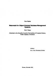
analysis) is beyond the scope of this paper. The example provided a mission for the system, but that is already in the solution space. Systems Engineers recognize today that once a concept for a solution is articulated, 70% of the cost of a solution is committed [2]. The process that will be followed for this paper is shown in Figure 3. We will refer to this as an
Figure 3 - Problem Solution Process
object oriented systems engineering (OOSE) process from this point forward since it is very similar to the process followed by software engineers performing object oriented analysis and design (OOAD). III.
ANALYZING STAKEHOLDERS
Once the problem statement has been articulated and a start to identifying stakeholders has begun, we can iterate the problem with the stakeholders. A more systematic approach to identifying stakeholders allows for a structured and complete elicitation of input and analysis of the problem and needs. The intent in elicitation is to achieve as complete an understanding of the problem and needs as possible [3]. Many systems fail as a result of missing an important stakeholder. Many techniques can be used to uncover the stakeholders for a particular context. The following provides questions that should be explored during elicitation: • What is the problem context, if it is a system or set of systems you are replacing, what actually comes in contact with the system? • Who would be involved in a project to provide a solution and who is involved in the products lifecycle? • What are the operational scenarios? • What is the story for an operational solution? • Who is going to pay for the solution, and who is paying for the existing situation? • What are the regulations and policies that apply in the current context and that might apply to a solution? As the authors worked through the FireSAT model for this paper, these questions were addressed systematically, developing a list of stakeholders. Success criteria are
identified, that is those conditions that enable each stakeholder to declare success. The major stakeholders identified in the exercise, and their success criteria include: • Forest Service o Early detection of fires before they become wildfires o Reduce costs to control wildfires based on budgets o More budget to allocate to environmental stewardship o Improve public perception of Forrest Service o Improve public safety due to wildfires o Firefighters at less risk o Having adequate firefighters to fight wildfires o Improve information to characterize and predict wildfire behavior • Firefighters o Effective evacuation of incidental personal (pubic & media) o Improved command and control in positioning of firefighters o More manageable fires that put me and team at less risk and fatigue • Residents o Early detection of fires resulting in less risk to property and life and reduce need for evacuation. o Better information on fires and potential wildfires as well emergency response o Communication to loved ones on situation awareness • Insurance Companies o Reduce claims due to wildfires o Remain competitive and maximize profits When systematic and complete analysis is performed, many stakeholders may be identified. A large part of Systems Engineering is finding effective ways of managing complexity with acceptable risk. For the FireSAT problem, the authors analyzed the set of stakeholders for the “function” they provided in the context. This allows one to group or identify classes of stakeholders. Once a functional partitioning is made, a higher order understanding of the stakeholder interaction can be analyzed. In Tables 2 and 3 there is first a list of the FireSAT stakeholders by function then an N2 diagram showing the interaction of the functional stakeholders. The translation from the functional analysis of the stakeholders and the N2 diagram to a structural view of stakeholders using SysML is shown in Figure 4. The combination of a well-known tool in Systems Engineering and the Class or Block diagram in the UML/SysML provides complimentary ways of expressing the analysis of the stakeholders. As stakeholders and/or actor classes of stakeholders are identified, there is the opportunity to interview the set that appear to be most important and apply a technique of eliciting first a profile for the stakeholder or stakeholder class. Stakeholder profiles are a way to identify classes and provide
an aggregate view of stakeholder concerns. Table 4 is a stakeholder profile for the firefighter stakeholder. bdd Use Case Model [Stakeholder Relationships]
+Responder Nationa l Guard +Supplier
Land mass and env ironment
+Protects
+Supplier Responder +Protects
Monitori ng Information Source +Supplier
+Director
+Client
Firefi ghter
+Server
NOAA
Serv ic e Owne r and Resource Manager +Regulated by +Customer
Media Forest Serv ice
Wildlife
+Client +Client BLM Serv ice Beneficiary
People liv ing in Forests
+Client +Regulator +Regulated by +Regulator
NASA Serv ice Support
Regulator
Taxpayers
State Gov ernments
Other Gov ernments Contra ctors
Insurance companies
Commercial S pace Agencies Ground Station operation personnel
FCC Congress
Figure 4 - Structural View of Stakeholders Table 2 - Stakeholder Functions Existing Fire Detection Systems Land and Environment Media NOAA (National Oceanographic and Atmospheric Agency) FCC Congress FEMA Firefighter National Guard Insurance Companies Mortgage/Realtor Companies Other governments Residents State Governments Tax Payers Wildlife Bureau of Land Mgmt Forest Service Commercial Space Organizations Contractors for Satellite and Enabling Systems Ground Station operators, analysts, management NASA
Collaborating Systems Monitoring Information Source Monitoring Information Source Monitoring Information Source Regulator Regulator, Funding Source Responder Responder Responder Service Beneficiary Service Beneficiary Service Beneficiary Service Beneficiary Service Beneficiary Service Beneficiary Service Beneficiary Service Owner & Resource Manager Service Owner / Resource Manager Service Support Service Support Service Support Service Support
Table 3 - Stakeholder N2 Diagram Monitoring Information Source
Regulator
Responder
Monitoring Information Source Regulator Responder Service Beneficiary Service Owner & Resource Manager Service Support
Service Beneficiary
Supplier
Service Owner Service Support & Resource Manager Supplier Supplier Regulate
Responds
Protects
Client
Client Regulated by
Client
Regulated by
Customer Director
Regulate
Responder Client
Server
Client Supplier
Table 4 - Sample Stakeholder Profile Representative Description Type Responsibilities
Success Criteria Involvement
Who is the stakeholder representative to the project, what is their name(s)? Firefighter Expert at fire assessment and response, not very knowledgeable in information systems or computers. • Respond to a fire in a timely fashion • Garner resources to execute a proper response to a fire • Notify interested and concerned parties • Protect people, property, and environment • Train and plan for fire fighting scenarios Respond to fires and extinguish them with a minimal loss. The stakeholder is Involved in the project as a consultant. Figure 5- Firefighter Stakeholder Goals and Sub-goals
Deliverables
Concept definition documentation related to command and control during a fire fighting scenario.
Comments / Issues
IV.
Integration of resources and communication during real-time fighting of fire is a big issue. Accurate understanding of fire situation.
GOALS TO USE CASES
Up to this point in the FireSAT analysis, the systems engineer is still analyzing the problem space. As part of this analysis, use cases are identified to bring focus to the potential solution. Use cases are used to capture the operational scenarios obtained during elicitation, and represent the viewpoint or goals of the stakeholders. In Figure 5 the Firefighter goals and sub-goals are illustrated. Notice that the goals and subgoals go a step beyond identifying success criteria, which is a step beyond identifying an overall problem. The stepwise and iterative evolution to understanding the entire problem with the goal of creating a domain model that translates into a system model, is the aim of this approach. The likelihood of applying a successful solution is a function of having a good aggregate understanding of the problem, which is a process, and it is a process where we can apply systematic modeling.
As the use cases for each operational scenario, and the stakeholder goals and sub-goals are modeled, the overall goal of the system will become clear. Figure 6 shows the goal and subgoals of the Service Owner and Resource Manager - an abstracted actor that represents the Forest Service or BLM (Bureau of Land Management).
Figure 6- Service Owner and Resource Manager
At this point, one must be careful to not jump to the conclusion that one of the primary use cases of the FireSAT system is to extinguish the fire, even though it is one of the firefighter’s goal/sub-goals. While it has been determined that the firefighter is a stakeholder, it is not clear whether the firefighter is part of the FireSAT system, or just an actor. The FireSAT system boundary is a logical representation of the boundary between the users/stakeholders and the system under consideration. Once all of the operational scenarios and goal/sub-goals are identified, analysis of what is inside the system boundary of the FireSAT system, and what is outside the system, one can identify the major use cases of the system. Figure 7 represents the result of that analysis.
Figure 9 represents that logical grouping of capability. This might be considered an analogous diagram to that found in the original FireSAT case study (Figure 2) in that it is still a logical architecture. uc Command and Control Fire Response [Command and Control Fire Response]
Wildfire (from Actors)
Firefi ghter
Wildlife
(from Actors) Forest Serv ice
uc Use Case Model [Use Case Model]
(from Actors)
(from Actors) Command a nd Contr ol Fire Respose
FireSAT System Boundary
(from Use Case Model) Nationa l Guard Monitor landma ss for fires
(from Actors) Monitori ng Infor mation Source (from Actors)
Command and Control Fire Respose
Monitor /charac terize Activ e Fires
Figure 7 - FireSAT Primary Use Cases
These use cases are consistent with the goals described in the introduction by NASA and the Forest Service. They describe what the system should accomplish without describing how to accomplish the use case. The Command and Control (C2) Fire Response use case and the participating actors are shown in Figure 8. This is a good point to introduce the application of architecture patterns. Several models can be followed when architecting a C2 system. Some of the more common models include: • Plan, Detect, Control, Act • MAPE – Manage, Assess, Plan, Engage • OODA – Observe, Orient, Decide, Act • F2T2EA - Find, Fix, Track, Target, Engage, Assess Each of these models is favored by different groups, but each will work for a given C2 architecture. Moreover, each can be modeled as a pattern, based on previous successful system implementations. Cloutier & Verma [4] demonstrated, a generic C2 pattern can be adapted at this point of the process, modifying the pattern as necessary for the FireSAT mission. As the use cases are broken into smaller use cases, those use cases can be grouped into logical blocks of capability.
Ground S ystem operation personnel (from Actors)
Figure 8 - Command and Control Fire Response
Notice that the original FireSAT had both an Orbits & Trajectory element as well as a Launch element. While those are important and necessary elements, they are secondary to the main purpose of the system – to detect and monitor forest fires. The initial need statement stated, “The United States needs a more effective means to detect and monitor potentially dangerous wildfires”. Nothing in this need statement or in the stated goals was the space-based system mentioned. This architecture allows the system (or SoS) architect to continue to perform trade studies to determine an optimal approach to satisfy the need statement. While that FireSAT case study was intended to address a space systems engineering problem, at this point in this analysis, it has not been determined that a space based solution is the best solution, or a cost effective solution. Further analysis and trade studies would be necessary to make that determination. It may be that the mission may be addressed simply with a combination of existing systems with the addition of a number of high flying, long station time unmanned air vehicles. If in fact, the analysis points to a space based system, then the launch vehicle may be added to the Fire Monitoring Collaborating System block of Figure 9 since the launch vehicle interfaces with the satellite until it reaches final orbit. Orbit and trajectory functionality may be placed in the Fire Detection System – that being the satellite. The next step in this process would be for the systems engineer to begin to create activity diagrams for each of the use cases, modeling the tasks that must be performed to accomplish each use case. Those tasks are then allocated to the appropriate actors based on information gathered during the stakeholder interactions. If specific reports or messages
are exchanged between tasks, those too can be captured on these activity diagrams. It is important to keep this information at a high level at this point, and not get too detailed while understanding and modeling the system or SoS architecture. If it is necessary, sequence diagrams and state diagrams can also be used to help improve understanding during this work.
V. CONCLUSIONS This paper presented an alternate approach to arriving at a logical architecture for a complex system or SoS using an OOSE approach to elicit and capture the goals of system stakeholders through stakeholder interactions. Those goals are then translated into use cases and activity diagrams. Those use cases and activity diagrams are then analyzed to produce a logical architecture. System requirements are also captured and documented along the way. The more interesting aspect, that requires further investigation, is the differences in the structure of the logical architecture created from a functional or structured approach and the object-oriented approach. That is does a functional approach allow full modeling of the problem domain? Does a functional approach converge naturally too quickly on a solution or is it just the historic application of functional analysis that made it so for the FireSAT example? REFERENCES [1] Larson, Wiley and James Wertz, Space Mission Analysis and Design, 3rd ed., El Segundo, CA: Microcosm Press & Kluwer Academic Publishers, 1999. [2] Defense Systems Management College , Sept 1993 [3] Carson, R., et al., Requirements Completeness, 2004 INCOSE Symposium [4] Cloutier & Verma, Applying the Concept of Patterns to Systems Architecture, Systems Engineering Journal, Vol. 10, No. 2, 2007, Wiley Periodicals
Figure 9 - FireSAT Logical Architecture Derived Using OOAD
It is important to note that while the systems engineer is capturing and modeling the goals, subgoals, use cases and activity diagrams, system requirements – both functional and non-behavioral will begin to emerge. As these requirements are identified, they should be captured in the requirements management approach being used by the project. This might be through a dedicated requirements management tool such as DOORS, or in SysML requirements diagrams. However, what is important is that those captured requirements are linked to elements of the SysML model so that system capability and specific functionality can be traced back to the requirements for V&V. The added benefit of linking the requirements to the system models is that if something must change – either a requirement or an element, the systems engineer has the necessary links to perform an impact analysis of the proposed change. Finally, once the systems engineer completes the use case analysis with activity diagrams, the process repeats itself. Each of the activities on the activity diagrams become the use cases for the next step. Again, the actors must be discovered, their goals and subgoals understood, the use cases modeled, etc.