Hans-Peter Seidel4 ..... al. with some ideas from ray tracing NURBS by Martin et al. [15]: ... start values for the Newton-Iteration, we follow Martin at al. and.
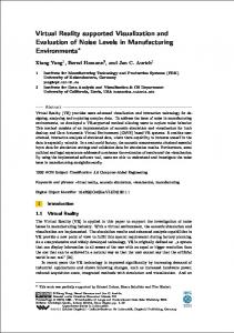
Applying Ray Tracing for Virtual Reality and Industrial Design Ingo Wald1,3 Andreas Dietrich2 Carsten Benthin3 Alexander Efremov4 Tim Dahmen3 4 5 4 Johannes G¨ unther Vlastimil Havran Hans-Peter Seidel Philipp Slusallek2 1 SCI Institute University of Utah
2 Computer
Graphics Group Saarland University
3 inTrace GmbH Saarbr¨ ucken, Germany
4 MPI Informatik Saarbr¨ ucken, Germany
5 Czech
Technical University Prague, Czech Republic
Figure 1: Several example screenshots from the presented framework, demonstrated on a complex Mercedes C-Class model: (a) The model consists of 320,000 B´ ezier patches and thousands of trimming curves that are directly and interactively ray traced without triangulation. (b) The model with ray traced shaders, e.g. glass and car paint, put into a surrounding scene made up of 200,000 triangles and a captured high dynamic range environment map. Note the accurate reflections, the refraction through the glass, and the smooth shadows from environment lighting. (c) The realistic interior appearance is achieved via a shader supporting bidirectional texture functions of measured samples from the corresponding real-world materials. (d) All these effects work together seamlessly, as can be seen on this view through the side window. At slightly reduced quality during interaction, these views can be rendered at 20, 14, 1.5, and 4.8 frames per second, respectively (640 × 480 pixels).
A BSTRACT Computer aided design (CAD) and virtual reality (VR) are becoming increasingly important tools for industrial design applications. Unfortunately, there is a huge and growing gap between what data CAD engineers are working on, what rendering quality is needed by designers and executives to faithfully judge a design variant, and what rendering capabilities are offered by commonly available VR frameworks. In particular, existing VR systems cannot currently cope with the accuracy demanded by CAD engineers, nor can they deliver the photo-realistic rendering quality and reliability required by designers and decision makers. In this paper, we describe a ray tracing based virtual reality framework that closes these gaps. In particular, the proposed system supports direct ray tracing of trimmed freeform surfaces even for complex models of thousands of patches, allows for accurately simulating reflections and refraction for glass and car paint effects, offers support for direct integration of measured materials via bidirectional texture functions, and even allows for soft environmental lighting from high dynamic range environment maps. All of these effects can be delivered interactively, and are demonstrated on a real-world industrial model, a complete Mercedes C-Class car. CR Categories: I.3.7 [Computer Graphics]: Ray tracing— [I.3.2]: Computer Graphics—Distributed/network graphics I.6.3 [Simulation and Modeling]: Applications Keywords: ray tracing, virtual reality, photo-realistic rendering 1
I NTRODUCTION
Computer aided design (CAD) and virtual reality (VR) are becoming increasingly important tools for industrial design applications. In particular large high-end engineering projects such as cars or airplanes are already engineered almost entirely digital, as the cost for
building physical mockups of such objects is prohibitively high. In practice visualization of such a digital design is not as straightforward as it might first seem, as there are several problems and complication arising from conflicting demands of the different groups involved in such a project, namely CAD engineers, designers, VR specialists, and company executives. CAD engineers work on the raw geometric data of the model, usually using freeform data such as NURBS surfaces [19]. The main objective of a CAD engineer is to model the individual geometric components of the car, and to perform evaluations like stress analysis, crash tests, or assembly simulation. For that reasons, CAD engineers are mostly interested in the highest possible geometric accuracy, as e.g. an assembly simulation can easily produce wrong results when working on approximated data.Photo-realistic rendering quality is usually not an objective for CAD designers – in fact, most of their tools do not even support reasonable material properties or even texture coordinates. Designers are in contrast to CAD engineers usually interested in producing photo-realistic results. As designers are responsible for the eventual look of the car, they strongly depend on the ability to predict how the model will look in reality. For this reason, designers usually prefer the highest rendering quality possible, and are particularly interested in realistic surface appearance, physically-correct lighting effects like shadows, accurate reflection and refraction, and if possible even global illumination. Decision makers use visualizations supplied by the designers or VR specialists to evaluate and judge different variants of a model. As a decision for or against a certain variant may have significant financial consequences, decision makers require that what they see in VR is faithful to reality, and is as accurate as possible. Additionally, they are often neither computer specialists nor graphics experts, and thus have to take their decisions solely based on what they are being shown by the VR specialists. VR Specialists have the task of taking the data prepared by CAD engineers and designers, and generating an interactive visualization. Unfortunately, the above-mentioned goals, high accuracy, high realism, and real-time performance, are in conflict to each
other: In order to satisfy interactivity constraints, virtually all of todays VR systems are built on triangle rasterization. With that however, rendering complete models at full geometric accuracy is not possible, as freeform surfaces cannot be rendered directly, and the amount of triangles generated by a high-quality tessellation is in the order of tens of millions of triangles. Thus, VR specialists usually deliver their presentation on specially prepared VR models of the real data. In the best case, this only involves a lot of various tools and manual effort for converting the model, tesselating, simplifying, removing invisible parts, and for fixing polygon orientations, degeneracies, and surface cracks, etc. In the worst case, this leads to costly remodeling a completely new, simpler version of the original CAD model. Apart from lack of geometric accuracy, existing VR tools fail to deliver the visual realism required by designers and decision makers. Whereas designers often make use of offline rendering processes, VR presentations have to deliver real-time frame rates, and thus often rely on approximations, manual model tuning, and “hand-painting” special textures to create reasonably nice images. This “model preparation” step as well involves many different tools, complex workflows, and a lot of manual effort. As a result such model preparation is usually measured in “person weeks”. 1.1
Limitations and Demands of Industrial VR
This process of working on specially prepared VR models is currently state-of-the-art in industry, but has several important drawbacks: First, preparation of special VR models takes time, so changes to the original data may take several days or weeks before they can be shown again in a VR presentation. This often leads to decision makers looking at outdated model variants. Apart from this, the personnel cost for the same tedious model preparation has to be spent anew for each iteration cycle. Second, the qualitative limitations of existing, rasterization-based VR systems usually fail to deliver the realistic appearance that designers and decision makers depend on, either leading to potentially wrong decisions, or the construction of costly physical mockups. 1.2
Contribution
This paper describes how current state-of-the-art interactive ray tracing techniques can be employed to form a virtual reality framework that starts to close the gap between engineers, designers, and virtual reality. In particular, the proposed system supports direct ray tracing of trimmed freeform surfaces even for complex models of thousands of trimmed patches, allows for accurately simulating reflection and refraction for glass or car paint effects, soft environmental lighting from high dynamic range environment maps, and even offers support for direct integration of measured materials via bidirectional texture functions (BTFs). All of these effects can be rendered interactively, and will be demonstrated on a real-world industrial dataset, a complete Mercedes C-Class model (Figure 1). 1.3
Outline
In the following, these individual components will be discussed and assembled step by step: Section 2 briefly sketches the freeform ray tracing module used for rendering the base geometry. Section 3 discusses the glass and car paint shaders applied for generating a realistic outside appearance, while Section 4 describes how smooth shadows from environmental lighting are generated. Section 5 then discusses how a high-quality car interior can be achieved by using ray traced BTFs, followed by some notes on our hardware setup and overall system performance in Section 6. Finally, in Section 7 we conclude with a discussion of some limitations and potential extensions of our approach.
2
F REEFORM R AY T RACING OF R EAL -W ORLD DATASETS
Before we can look into realistic surface and lighting simulation, we first have to be able to directly render the original model at all. In practice, this usually means having to support non-uniform rational B-spline (NURBS) surfaces [10], as these – due to their geometric properties and compact representation – are the de-facto standard used in CAD engineering. In the last two decades researchers have proposed several approaches for ray tracing NURBS surfaces [23, 18, 15, 28], but due to the high cost of evaluating the NURBS equations this is usually too slow for interactive performance. More recently Benthin et al. [4] have demonstrated ray tracing of bicubic B´ezier patches that allowed for interactive frame rates even on a single CPU. We build on a significantly modified variant of that framework (see Section 2.2).
2.1
NURBS to Bicubic B´ezier Surface Conversion
Since we only support bicubic B´ezier patches, we first have to convert the original NURBS surface to an arbitrary-degree, rational B´ezier representation, which can be done without any loss of accuracy [19]. This is achieved by increasing the multiplicity of each knot in the knot vectors of both parameter directions to the order of the NURBS surface in the corresponding parameter direction [19, 8]. Our model contains only non-rational surfaces, so no special handling of the rational part was necessary. As we currently only support non-rational B´ezier patches of degree 3 × 3, the degree of each B´ezier patch must then be either reduced or elevated, depending on the initial degree of the patch. This degree reduction of course may lead to a certain loss of accuracy, which must be handled by a user-specified tolerance threshold: If the degree of a B´ezier patch cannot be reduced without preserving the patch geometry below the tolerance threshold, the initial B´ezier patch must be subdivided in the direction where the B´ezier reduction step failed. This degree reduction is then applied recursively to each of the obtained sub-patches. The same strategy can also be used for converting the contour trimming curves, which are given by 2D NURBS curves in the surface’s parameter domain. In our example of the Mercedes C-Class model, the original data consists of a total of 69,067 NURBS surfaces with 392,491 2D NURBS curves that form 73,749 trimming contours. Converting first yields 308,095 B´ezier patches of arbitrary degree, which after degree reduction with error threshold yields 319,340 bicubic B´ezier patches (illustrated in Figure 2). The resulting number of trimming curves in the model is 1.46 millions, i.e., an average of 5 trimming curves per patch. Obviously, approximating NURBS surfaces by bicubic B´ezier patches also involves a certain loss of accuracy, and thus seems to conflict with the goal of working on the original CAD data. Nevertheless, typical NURBS ray tracing algorithms [23, 15, 18] are approximative in nature as well. Moreover, we already achieve significantly a higher accuracy in contrast to surface triangulation. In particular, smooth B´ezier patches allow for zooming onto the surface without eventually seeing the triangular discretization at the silhouettes. Additionally, as the trimming curves are fully integrated into the rendering process, there is no need to cope with all the problems that usually arise from finding suitable triangulations along the trimming contours. Note that the main strength of that approach is its full automaticity: Whereas triangulation often require manual user intervention, i.e. for tuning parameters and fixing cracks, degeneracies etc. in the triangulated surface, the described method can be realized as a fully automatic batch process that requires no user intervention at all.
Once a hitpoint on an B´ezier patch is found, the trimming curves need to be evaluated. As in the given model some patches have up to several hundred trimming curve segments, an additional hierarchy was required for determining these segments as well, which is realized by yet another 2D kd-tree. Of course, we follow Martin et al., and determine completely trimmed patches before building the 3D kd-tree. Also, when building the kd-tree we are taking care to consider the trimming curves when computing the bounding box of the sub-patch, which minimizes the number of sub-patch intersections that later get trimmed anyway. Even with all these optimizations, ray tracing the C-Class model is still quite demanding, due the huge geometric complexity and the large number of trimming curves. Nevertheless, interactive performance can be achieved: On one dual 2.43 GHz AMD Opteron PC, the systems runs with 0.86 respectively 3.01 frames per second for the interior respectively exterior view shown in Figure 2. Note that the interior view in is one of the most costly views due to the huge number of patches on the steering wheel, radio, and air vents. Figure 2: The Mercedes C-Class model used in all experiments consists of 69,067 trimmed NURBS patches with 392,491 2D NURBS trimming curves, which are represented using 319,340 trimmed bicubic B´ ezier patches along with 1.4 million B´ ezier trimming curves. Left: Resulting model. Right: Color-coded B´ ezier patches showing the geometric complexity. Note that the colored regions do not represent a tesselation, but a smooth B´ ezier patch each.
2.2
3
R EALISTIC S URFACE A PPEARANCE
With the ability to accurately render the original CAD geometry, we next focus on realistic material descriptions. Because ray tracing accurately simulates the physics of light transport, and automatically accounts for global effects like reflection etc., we can fully concentrate on local material descriptions, which are realized via individual surface shader plug-ins.
Efficiently Ray Tracing of Freeform Models
Once a B´ezier representation is generated, that representation is fed into the B´ezier ray tracing plug-in. Though this framework builds on earlier work on Benthin et al. [4], the original framework eventually turned out to be quite problematic for a real-world dataset such as the C-Class model. This is mainly due to the excessive number of trimming curves, multiple patches overlapping and intersecting themselves, and untrimmed patches being very large in relation to their trimmed counterparts. For example, the high accuracy requirements resulted in a high patch refinement level that got quite costly. Furthermore, most of the traversal steps were performed on the patch level, which – as overlapping patches have to be intersected one after another – resulted in a huge amount of traversal steps. This is particularly problematic if these costly traversals then result in a hitpoint outside the trimming domain. The the original system already supported trimming curves, but was optimized for only one or two trimming curves per patch, and could not cope with the huge amount of trimming curves in the C-Class model. As a result, the existing system had to be completely reengineered. It now combines the original approach of Benthin et al. with some ideas from ray tracing NURBS by Martin et al. [15]: Instead of performing a fixed number of de Casteljau subdivisions during traversal as done in [4], we now also use Newton-Iteration for computing the ray-patch intersections. In order to obtain good start values for the Newton-Iteration, we follow Martin at al. and subdivide the B´ezier patches into multiple sub-patches before rendering that are then organized in an additional index structure. Generating sub-patches for the original 319,340 B´ezier patches yields 1.2 million bicubic sub-patches, whose accuracy clearly exceeds the roughly 1 million triangles in a triangulated counterpart of the model. Instead of using a bounding volume hierarchy for these subpatches we use kd-trees, which allows for reusing the fast ray traversal algorithms as proposed by Wald et al. [24]. In particular for regions where multiple patches overlap, we now no longer have to traverse each of these patches separately, but rather perform a single traversal in the 3D kd-tree, and for each encountered sub-patch only have to perform the final Newton-Iteration.
3.1
Car Paint
As most of a car’s outside is made up of car paint, a realistic appearance of this material is very important. Car paint exhibits a wide range of optical effects, including as diverse ingredients as pearlescence and sparkling effects [9]. However, not all of these effects are equally important. One of the most obvious characteristics of car paint is its high specularity, which usually results in the car reflecting the surrounding environment. In typical VR systems, this effect is usually achieved by a highly specular Phong or ClearCoat [21] shader with an appropriately chosen reflection map. Unfortunately, reflection maps usually result in significant artifacts, due to their “infinite distance” assumption that is violated by nearby geometry. This is particularly the case for highly curved regions such as at the fenders or door handles. Additionally, the infinite distance assumption makes reflection maps notoriously hard to use for the interior, where special reflection maps have to be computed for each object supposed to be reflective. Furthermore, reflection maps do not allow for self-reflection, which is e.g. problematic for the hood, which when standing in front of a car usually reflects the roof and windscreen (as can be seen in Figure 3). Plausible reflections must also account for nearby objects such as the street or other cars. Thus, reflection maps need to be carefully constructed anew for each environment, and often have to be manually post-processed to look acceptable. When building on a ray tracer, these limitations can be easily avoided by exact computation of real, accurate reflections. In order to improve realism, we usually surround the car by fully modeled environments. We still use an environment map for very distant geometry such as the sky, but due to a ray tracer’s good scalability in geometric complexity one can represent a large part of the surroundings by real geometry. Its easily possible to switch between different environments during runtime, while all reflections will be fully accurate and correct, without any manual effort. The reflectivity of car paint varies depending on the angle at which the surface is seen, which cannot be captured with a standard Phong BRDF model. For this reason, its better to use a shader based on a slightly more accurate variant of the ClearCoat model,
most importantly termination of low-contributing light paths – are supported in our current framework as well. The impact of a realistic glass simulation can be seen in Figure 4, which compares the rendering quality of a ray traced glass shader with the quality achieved by a semi-transparent plane as used in standard industrial VR systems. Unfortunately, we could not demonstrate this effect for the car lights as well, because geometric data for the lamps was not available for this model. Figure 3: As most of a car’s outside body is covered with car paint, a realistic simulation of its optical properties is quite important. Left: Car with a typical Phong shader, illuminated by the HDR environment map. Right: With a ClearCoat shader that simulates Fresnel effects in the car paint and computes the resulting reflections. Note the accurate reflections (as opposed to a reflection map), as well as the varying reflectivity depending on the viewing angle.
which essentially simulates a small layer of glass (the transparent coating) on an otherwise Phong-style material. The angular dependent reflectivity then is a result of the Fresnel factors for the coating. Of course, this relatively simple model for car paint is still not perfect. For example, it supports neither glossy reflections nor pearlescence or sparkles. However, in practice the current set of effects has shown to be sufficient, while the computation can be done very fast. The difference between such a model and a Phong shader can be seen in Figure 3. Note that though these effects seem very subtle (in particular for still images and when printed on paper), there is explicit industrial demand for these features. 3.2
Glass
Of even higher importance for design reviews, in particular for cars, is Glass. Many other materials can – at least after enough manual tuning and hand-painting of textures – still be reasonably well represented by appropriately textured Phong models, or specially designed fragment shaders on rasterization hardware. For glass however, this is not the case. This because glass is “recursive” in nature, as the color seen by an incoming ray hardly depends on the hit object at all, but almost entirely on what is seen in the reflected and refracted directions. Thus, accurately rendering realistic glass with anything other but recursive ray tracing is next to impossible. Therefore, in typical VR systems glass is usually modeled by a simple semi-transparent plane, with a slight gray-blue tint to make the glassy object visible at all. This simplistic model is still state-of-the-art in most of todays industrial grade VR systems, but is almost useless for reliable design decisions. For glass, even very subtle effects, such as its slight reflectivity, can have a critical influence. For example, reflections of bright parts in the windshield or side windows can result in significant security issues (e.g., glare, occlusion, or distraction). Accurately simulating such effects, in particular during interaction, where different configurations can be evaluated from different views, are extremely important for designers. In practice this is especially important for the head and rear lights, due to the complex optical light paths inside these objects. For a ray tracer on the other hand, glass is a pretty straightforward material to compute. Its physical behavior is well understood, and essentially only at most two new rays (for reflection and refraction, given that dispersion is not accounted for) have to be shot. For this reason, Glass simulation was one of the first industrial applications for real-time ray tracing [2]. Essentially, we use exactly the same concepts, except for a few minor optimizations. All the effects described in [2] – reflection, refraction, Fresnel terms, and
4
S MOOTH S HADOWS AND RONMENTAL L IGHTING
H IGH DYNAMIC R ANGE E NVI -
Apart from materials, a realistic appearance of a car also depends strongly on the incident illumination. For datasets such as cars the most natural source of illumination is its surrounding environment. For a clear, sunny sky, illumination can be simulated by just placing a single directional light source into the respective sun direction. However, in reality environmental illumination usually is much more complex, resulting in smooth shadows and other effects. Because soft shadows are costly to compute, typical VR systems either use sharp shadows only (if at all), or confine themselves to a handmade shadow texture placed below the car. Both methods involve manual effort, have to be re-done for every change of the environment, often create inconsistencies between the shadows shown and the shadows as expected by the given environment, and generally fail to produce a physically-correct appearance. 4.1
Discretizing Environmental Lighting
Environmental lighting can be efficiently realized based on high dynamic range environment maps in the spirit of [14, 1]. This ideally should work fully automatic, and without any user invention except for specifying the environment map to be used. The respective light shader (a plug-in that controls light source behavior, similar to a surface shader) will access the same HDR environment map that is also used to determine the resulting color for rays that do not hit any geometry. Thus, the shadows always stay consistent with the chosen environment.
Figure 4: Realistic simulation of glass effects has a strong impact on the level of realism of a rendered image. Left: Rendering glass materials as semi-transparent surfaces as usually done in rasterizationbased VR systems. Right: With a physically-correct, ray traced glass shader. Top: View from drivers seat (effect slightly emphasized to reproduce on paper). Note the reflection of the car interior over the left rear-view mirror. Bottom: View from the outside.
Figure 5: Smooth environmental lighting: Left: Using 3 samples only, producing sharp shadows. Center: With interleaved sampling and discontinuity buffering at roughly frames/s. Right: After accumulation of more samples. Also note the shadows in the background.
Unfortunately, producing smooth environmental lighting by randomly sampling an environment map often produces Monte Carlo noise [1]. As a result this becomes quite costly due to the large number of samples required to reduce the noise. An alternative is to discretize the illumination from the environment by placing “virtual” directional as shown in [1, 14] that are then used to illuminate the scene (see Figure 5. In order to support progressive image enhancement (see next section), for each loaded environment map we generate N such samples in a progressive way, i.e., one can always take the first k of these N samples, and by simply scaling their power by Nk , can use these k samples to get a coarser but nonetheless consistent representation of the environmental illumination. 4.2
Interleaved Sampling and Discontinuity Buffering
For reasonable quality of the environmental lighting, at least 20 to 40 samples (i.e. directional lights) would have to be computed, and high-quality images would require even more samples. Unfortunately, due to the high cost of tracing the corresponding shadow rays, even using only 20 samples per pixel is not affordable during interaction. To maintain interactive performance, we use interleaved sampling and discontinuity buffering as originally proposed for the Instant Global Illumination method [26, 3]. In that approach, not every pixel computes every shadow sample, but every other pixel in a 3 × 3 or 5 × 5 pattern uses a different set of directional lights, whose contributions are then combined in images space in an a-posteriori filtering step. As this filtering step only filters the irradiance (and not the final pixel colors), and additionally restricts filtering to pixels whose respective surface points pass certain continuity criteria, blurring over material or geometric discontinuities is minimized. Note that this technique was also already used in [14]. Using this method, the effective number of samples used per pixel after filtering is 9 respectively 25 times the number of samples for each individual pixel, achieving almost the same quality as when actually using that many samples per pixel. Thus, a reasonably good quality can be achieved even during interaction, where only a few (2–5) shadow rays are affordable per pixel. The difference can be seen in Figure 5. As soon as camera motion stops, we progressively improve image quality by computing successive images of the same viewpoint with new random samples, and accumulate the resulting images (see Figure 5). In summary, with only 2–5 samples we achieve reasonably smooth shadows and environmental lighting even during interaction, and high-quality shadows after accumulating only a few frames . In practice, this has shown to not to be that problematic, as the coarser shadow quality without accumulation is less perceptible during interaction. Note that the shadows not only comprise the
shadows of the car cast onto the floor, but also include the shadows the environment and the car cast onto themselves. 5
S UPPORT FOR M EASURED R EAL -W ORLD M ATERIALS USING B IDIRECTIONAL T EXTURE F UNCTIONS
While the outside appearance can be reasonably well handled with the techniques described above, the car’s interior is more complex, including materials such as cloth, (structured) plastic, carpet, metal, leather, and wood. Most automotive companies have extremely high quality requirements for realistically rendering “their” materials, which cannot be satisfied using a common Phong reflection model with textures. Even bump mapping (i.e. simply perturbing surface normals) can only insufficiently capture the intricate lighting effects happening at the microstructure level of these materials. As a consequence, there is a huge demand to acquire the surface characteristics of samples of real materials, and to use those during rendering. 5.1
Bidirectional Texture Functions
Even if more complex BRDF functions are used instead of a simple Phong model this typically assumes a homogeneous surface, and cannot capture the complex surface patterns of the materials we are most interested in. Dana et al. [6] have proposed to sample the texture of the material for many different light- and viewing-directions, yielding so-called bidirectional texture functions (BTFs). This approach has later been refined by M¨uller et al., who proposed to compress BTFs using clustered principle component analysis (PCA) [16, 17]. They also described an automatic BTF acquisition setup. For the given Mercedes C-Class model, all of the surfaces had already been scanned by Bonn University in the course of the RealReflect project [20]. The resulting BTF data has been made available to us, courtesy of DaimlerChrysler AG. These BTFs are originally provided as 256 × 256 pixel textures for every combination of the 81 × 81 samples of the possible viewing and incident lighting directions. Due to the HDR acquisition process, each of these 256 × 256 × 81 × 81 samples contains an RGB float triple. This huge amount of data (12 GByte per material) is compressed using clustered PCA with 32 clusters and 8 components per cluster. In addition to a reference to one of the PCA clusters, each of the 256 × 256 texels contain the 8 float weights for reconstructing the PCA, while each of the 32 clusters contains eight 81 × 81dimensional base components, resulting in only roughly 24 MByte per material. During rendering, the BTF data for each (u, v, ωi , ωo ) sample (surface parameters, incident and outgoing light direction) is then decompressed on the fly from that PCA data.
5.2
Smooth Reconstruction using Quadrilinear Interpolation
Unfortunately, the dataset contains only values for 81 × 81 discrete (ωi , ωo ) pairs. Thus, for any two given view and light direction vectors, some value has to be reconstructed from these spares samples. With only 81 samples on the hemisphere, simply taking the nearest available sample results in severe discretization artifacts. To obtain visually pleasing results, it is therefore necessary to smoothly interpolate the data from multiple adjacent sample directions. The BTFs are sampled on a hemisphere, where the elevation angle θ is discretized into 15 degree steps, at θ = 0, 15, 30, 45, 60, 75 degrees. The BTF does not actually represent a discretized BRDF fr (x, ωi , ωo ), but rather its cosine-weighted counterpart fr (x, ωi , ωo ) cos θi . Thus, for the θ = 90 ring all samples are zero, and need not to be stored. The azimuth angle φ discretization on each such θ ring is chosen proportional to sin(θ ), ranging from 24 15-degree steps for θ = 75, to a single sample at the pole . This highly irregular sampling complicates interpolation (see Figure 6). We experimented with both a triangulating of the sample points, and with weighted distance interpolation, but have finally chosen to first linearly interpolate on each of the two nearest θ rings, and then to interpolate the result in θ direction, yielding a smooth reconstruction. Unfortunately, this bilinear interpolation is very expensive: First, determining the correct sample indices and weights is costly, since many special cases have to be considered for each lookup (e.g., the missing samples for θ > 75). Second, extracting a sample from the BTF dataset requires a costly PCA-decompression for each sample (i.e., accumulation of several terms addressed through many indirections). Third, we have to smoothly interpolate for both in- and outgoing direction, and thus have to perform a quadrilinear interpolation, which means we have to perform these PCA lookups 16 times for each pair of directions, and have to filter the resulting 16 values. Finally, as the incident direction ωi varies for each light source, this procedure has to be performed anew for every light source. As a result, BTF evaluation is extremely demanding, and the weighting of the light samples is often more expensive than shooting the shadow ray itself. 5.3
Interior Lighting
As discussed in the previous section, we use environmental lighting to produce a realistic outside appearance. For the interior of the car, one would actually have to compute a full global illumination solution. In principle, it would be possible to use an interactive global illumination algorithm as proposed in [26, 3]. These methods however are specially optimized for mostly-diffuse scenes, and do not easily work for as complex shaders as glass or BTFs. Furthermore, the complex lighting in the car interior would require too θ=0 θ=15 θ=30 θ=45 θ=60 φ=0
φ=180
Figure 7: Comparison of using BTFs vs. the usual textured Phong surfaces by a view into the car’s cockpit. Left: Textured Phong. Right: Using measured BTFs. Top: Entire cockpit. Bottom: Zoom onto the wood and leather.
many virtual light sources for achieving reasonable quality, which would probably not allow for interactive performance anymore. Precomputing global illumination using a Radiosity method [5] is not helpful either, as Radiosity is a directionally independent quantity, and is thus useless for illuminating BTFs. Precomputed Radiance Transfer methods [22, 13, 7] might be a reasonably alternative, but have never been applied to such models, yet. We therefore do not compute global illumination in the car interior, but only the direct environmental illumination, plus a manually placed point light that approximates indirect lighting. In practice, most of the illumination patterns (such as shadows) are due to direct illumination, anyway, so the level of realism is still sufficiently high, even without supporting indirect illumination so far. Nevertheless, in order to remove this final limitation in physical correctness, we are looking into precomputing global illumination in a directionally dependent way. Preliminary results are available and look promising, but are not yet available for practical use, and will not be discussed in this paper. 5.4
BTF Quality
While the high computational costs of BTFs is obviously a strong disadvantage, the increased level of realism makes more than up for that. Figure 7 shows a comparison of the measured BTF material versus a textured Phong material. Note that the textures on the Phong model have already been provided with the original model. These are photographs from the original materials, and have been optimized to produce a better image quality. Even in comparison to this already high quality, BTFs further increase the quality, in particular for cloth, wood, and leather ( Figure 7). Although this effect can hardly be seen in still images, it becomes clearly apparent during interaction, when the viewing and/or lighting directions change. To our knowledge, this is the first time that BTFs have been ray traced or used in virtual reality applications at all.
φ=360
6 Figure 6: Quadrilinear interpolation for reconstructing a smooth representation from the sampled BTF using successive linear interpolation in each dimension. This example shows a two-dimensional example, while the BTF interpolation across two surface parameter directions is four-dimensional.
F INAL I NTEGRATION AND OVERALL R ESULTS
In the preceding sections, we have discussed all the individual components of our framework, starting with directly ray tracing the complex, trimmed freeform geometry of the car, over various surface shaders (including glass and car paint), an efficient method for
computing environmental illumination, and support for measured materials using bidirectional texture functions. Using a ray tracing based framework, combining all these individual effects works mostly automatic: For example, a view of the inside will not only show the BTFs directly, moreover such surfaces will be correctly reflected in the mirrors or off the glass. Similarly, the environment – which is to a large degree modeled by real geometry – correctly casts smooth shadows like the car as well, and is correctly visible through the glass shaders, and is also correctly reflected in the car paint, on the mirrors, etc. Some examples of the final rendering quality can be seen in Figure 8 and on the color page at the end of the paper (Figures 9–12). Note that although these images look like offline renderings, they can be computed at interactive rates. Our implementation is realized via shaders and plug-ins for the OpenRT engine [24], all the features of an existing OpenRT-based VR application are available for our framework as well. For example, the user can define lighting, geometry, and shading scenarios, can specify and interactively edit cutting planes, surface shaders, and light sources, can switch variants and move objects, etc. 6.1
Hardware Setup
As already discussed in the previous sections, the targeted level of accuracy and quality does not come for free: For a model as complex as the Mercedes C-Class, the freeform ray tracing incurs a high computational cost (see Section 2). The complex shaders further add to this cost. Furthermore, due to the complexity of the employed shaders we cannot use fast packet-traversal code described in [27], and rather have to use slower single-ray traversal code. Finally, the extensive use of secondary rays for computing shadows, reflection, refraction, etc. additionally affects performance. In order to achieve interactive performance, we used the parallelization capabilities of the OpenRT engine, and ran the system on multiple PCs. As a dedicated ray tracing cluster unfortunately was not available, we used the commodity PCs in our lab for our experiments. More precisely, we used a mix of 4 dual Intel Xeon (3 GHz) machines, 1 quad AMD Opteron (2.4 GHz), and 9 various dualOpteron machines ranging from 1.8 to 2.4 GHz (30 CPUs in total). All machines were connected via multiple switches, some via 100 MBit Fast Ethernet, others via Gigabit Ethernet. Neither the machines nor the network were available for the ray tracer exclusively, and were used by other applications as well. 6.2
Rendering Performance
On average we achieve interactive performance of 1.5 up to more than 20 frames per second at a screen resolution of 640×480 pixels, depending on viewpoint and complexity of features seen. The views in Figure 8 can be rendered at 1.5 and more than 10 frames per second, respectively, and even the accumulated images are gained after only a few frames of progressive rendering . Note that the interior view is one of the most expensive viewing situations in the entire car. Though it could not be tested, it can be expected that a dedicated ray tracing cluster, with a better network and available for exclusive use by the ray tracing application, would yield even better results. Although the compute power employed for these experiments may at first seem quite considerable, for industrial standards it is actually not significant. For example, a dedicated ray tracing cluster of 50 dual-Opteron nodes has recently been set up at a major German car manufacturer, where it is used to drive a 3200 × 1200 pixel PowerWall for ray tracing based design reviews. We estimate the compute power of such a setup to be sufficient for running our complete framework also in fullscreen mode.
Figure 8: The final system. Top: Driver’s view of the interior. Bottom: Outside view. Note the smooth shadows, the correct reflections in the car’s paint, the subtle glass effects in the windshield, as well as the detailed interior. These views can be ray traced at 1.5 (top row), and more than 10 frames per second (bottom row) at 640 × 480 pixels, respectively. Left: During camera motion. Right: After accumulating several frames.
7
S UMMARY AND C ONCLUSION
In this paper, we have described a novel VR framework that is entirely based on real-time ray tracing, and that particularly targets a very high level of visual realism. The presented system offers direct ray tracing of freeform surfaces, high-quality rendering of car paint and glass materials, smooth shadows from high dynamic range environment maps, and support for measured materials using bidirectional texture functions. 7.1
Comparison to Existing VR Solutions
In comparison to existing rasterization-based VR solutions, the proposed methods offer a number of advantages. Directly ray tracing a freeform model allows for significantly improved geometric accuracy of millions smooth B´ezier sub-patches. Apart from this pure geometric complexity, directly ray tracing trimmed B´ezier patches removes the need for generating a complex triangulation of the model, which significantly simplifies the VR workflow. Using ray traced surface shaders for glass and car paint delivers accurate and reliable images, and for the first time allows for predictive rendering even during interactive design reviews. Similarly, smooth environmental illumination greatly exceeds the realism previously available in VR applications. All of these features have so far only been possible during offline rendering, and are usually not available in industrial VR systems at all. Some of these features are already being worked on also for rasterization hardware (see e.g. [16, 12]), but few of such research results are actually used in industry. Finally, we believe our system to be the only one to support all of these effects at the same time and in a fully integrated way. 7.2
Shortcomings and Limitations
Even though the presented system qualitatively exceeds existing VR solutions, there are also several open issues. First of all, due to the high computational cost of the freeform geometry, complex surface shaders, and illumination effects, we
are currently restricted to relatively low resolutions (640 × 480 pixels) and frame rates (less than 10 fps), while already requiring a considerable amount of aggregate compute power. On the other hand, hardware cost is often one of the lesser problems for industrial applications, and much larger clusters than the one used in our experiments have already been installed for similar purposes. On such a hardware platform, it should even be possible to reach fullscreen resolutions at interactive frame rates. Even so, the compute power required for driving a fully interactive VR setup (including high-resolution output devices) is still significant, and considerably higher than that for typical rasterization-based VR systems. On the quality side, there is lot of room for improvements: For example, the simple logarithmic tone mapping used in our system works well in practice, but is far from state-of-the-art in offline rendering technology, where much better tone mapping algorithms are being used. Although such tone mapping techniques are well-known, in particular the global operators are difficult to implement in a distributed rendering environment. Similarly, the car paint shader we used is a rather trivial shader. Much better car paint models – often generated via acquisition of real car paint BRDFs – are well known. While the quality far exceeds typical VR setups, we do not offer all the rendering effects that high-end offline renderers provide. Not supporting global illumination, in particular in the interior of the car, is a severe limitation. Offline rendering packages typically feature global illumination effects, and thus generate far more accurate and photo-realistic images than we do. Developments into these areas are already under way. A prototypical implementation of a precomputation-based technique for rendering the given model with full global illumination (including caustics, highlights, glossiness, BTFs, illumination through the windshield etc.) is already available [25]. Right now, however, this method is not yet fully integrated into the given system.. Similarly, in a related project G¨unther et al. [11] have shown that a much higher realism for car paint can be realized with specially designed shaders that are based on acquisition, digitalization, and fitting of real-world car paint samples. In summary, we reach neither the quality standards of high-end offline renderers, nor the interactivity of standard VR applications. We do, however, offer significantly more realistic images than existing VR applications that are at least close to offline renderings – and still at interactive rates. ACKNOWLEDGMENTS This paper would not have been possible without the gracious support of DaimlerChrysler AG, who provided the C-Class Model in both triangulated and NURBS versions, and who have granted permission to use the measured BTF data. We would also like to thank the RealReflect project, in particular the Computer Graphics Group at Bonn University, for providing the BTF data and help in numerous ways. Finally, we have to thank the system administration groups of the Max-Planck-Institute for Computer Science Saarbr¨ucken and Saarland University for providing the required compute power. R EFERENCES [1] Sameer Agarwal, Ravi Ramamoorthi, Serge Belongie, and Henrik Wann Jensen. Structured Importance Sampling of Environment Maps. Computer Graphics (Proceedings of ACM SIGGRAPH), 22(3):605–612, 2003. [2] Carsten Benthin, Ingo Wald, Tim Dahmen, and Philipp Slusallek. Interactive Headlight Simulation – A Case Study of Distributed Interactive Ray Tracing. In Proceedings of the 4th Eurographics Workshop on Parallel Graphics and Visualization (PGV), pages 81–88, 2002.
[3] Carsten Benthin, Ingo Wald, and Philipp Slusallek. A Scalable Approach to Interactive Global Illumination. Computer Graphics Forum (Proceedings of Eurographics), 22(3):621–630, 2003. [4] Carsten Benthin, Ingo Wald, and Philipp Slusallek. Interactive Ray Tracing of Free-Form Surfaces. In Proceedings of Afrigraph, pages 99–106, November 2004. [5] Michael F. Cohen and John R. Wallace. Radiosity and Realistic Image Synthesis. Morgan Kaufmann Publishers, 1993. [6] Kristin J. Dana, Bram van Ginneken, Shree K. Nayar, and Jan J. Konderink. Reflectance and Texture of Real-World Surfaces. ACM Transactions on Graphics, 18(1):1–34, 1999. [7] Kirill Dmitriev, Thomas Annen, Grzegorz Krawczyk, Karol Myszkowski, and Hans-Peter Seidel. A CAVE System for Interactive Modeling of Global Illumination in Car Interior. In ACM Symposium on Virtual Reality Software and Technology, pages 137–145, 2004. [8] Alexander Efremov. Efficient Ray Tracing of Trimmed NURBS Surfaces. Master’s thesis, Computer Science Department, University of Saarland, 2005. [9] Sergey Ershov, Konstantin Kolchin, and Karol Myszkowski. Rendering Pearlescent Appearance Based on Paint-Composition Modeling. In Computer Graphics Forum, Proceedings of Eurographics 2001, pages 227–238, 2001. [10] A. R. Forrest. The Twisted Cubic Curve: A Computer-Aided Geometric Design Approach. Computer Aided Design, 12(4):165–172, 1980. [11] Johannes G¨unther, Tongbo Chen, Michael Goesele, Ingo Wald, and Hans-Peter Seidel. Efficient Acquisition and Realistic Rendering of Car Paint. In G¨unther Greiner, Joachim Hornegger, Heinrich Niemann, and Marc Stamminger, editors, Proceedings of 10th International Fall Workshop - Vision, Modeling, and Visualization (VMV) 2005, pages 487–494, Erlangen, Germany, November 2005. Akademische Verlagsgesellschaft Aka. ´ Bal´azs, and R. Klein. Real-time out-of-core trimmed [12] M. Guthe, A. NURBS rendering and editing. In Vision, Modeling and Visualisation 2004, pages 323–330, November 2004. [13] Jan Kautz, Peter-Pike Sloan, and John Snyder. Fast, Arbitrary BRDF Shading for Low-Frequency Lighting Using Spherical Harmonics. In Rendering Techniques 2002, pages 301–308, 2002. (Proceedings of the 13th Eurographics Workshop on Rendering). [14] Thomas Kollig and Alexander Keller. Efficient Illumination by High Dynamic Range Images. In EGRW ’03: Proceedings of the 14th Eurographics workshop on Rendering, pages 45–50. Eurographics Association, 2003. [15] W. Martin, E. Cohen, R. Fish, and P. Shirley. Practical Ray Tracing of Trimmed NURBS Surfaces. Journal of Graphics Tools, 5:27–52, 2000. [16] G. M¨uller, J. Meseth, and R. Klein. Compression and Real-Time Rendering of Measured BTFs using Local PCA. In Vision, Modeling and Visualisation 2003, pages 271–280, November 2003. [17] Gero M¨uller, Jan Meseth, Mirko Sattler, Ralf Sarlette, and Reinhard Klein. Acquisition, Synthesis and Rendering of Bidirectional Texture Functions. In Eurographics 2004, State of the Art Reports, pages 69– 94, 2004. [18] Steven Parker, William Martin, Peter-Pike Sloan, Peter Shirley, Brian Smits, and Charles Hansen. Interactive Ray Tracing. In Proceedings of Interactive 3D Graphics, pages 119–126, 1999. [19] Les Piegl and Wayne Tiller. The NURBS book, 2nd edition. SpringerVerlag, Inc., 1997. [20] RealReflect. The Real Reflect Project. http://www.realreflect.org. [21] Silicon Graphics, Inc. ClearCoat360. http://www.sgi.com/products/software/clearcoat, 1998. [22] Peter-Pike Sloan, Jan Kautz, and John Snyder. Precomputed Radiance Transfer for Real-Time Rendering in Dynamic, Low-Frequency Lighting Environments. In ACM Transactions on Graphics (Proceedings of ACM SIGGRAPH), pages 527–536, 2002. [23] M. Sweeney and R. Bartels. Ray Tracing Free-Form B-Spline Surfaces. IEEE Computer Graphics and Applications, 6(3):41–49, 1986. [24] Ingo Wald. Realtime Ray Tracing and Interactive Global Illumination. PhD thesis, Computer Graphics Group, Saarland University, 2004. [25] Ingo Wald. High-Quality Global Illumination Walkthroughs us-
ing Discretized Incident Radiance Maps. Technical Report UUSCI2005-010, SCI Institute, University of Utah, 2005. available at http://www.sci.utah.edu/∼ wald. [26] Ingo Wald, Thomas Kollig, Carsten Benthin, Alexander Keller, and Philipp Slusallek. Interactive Global Illumination using Fast Ray Tracing. In Paul Debevec and Simon Gibson, editors, Rendering Techniques 2002, pages 15–24, Pisa, Italy, June 2002. Eurographics Association, Eurographics. (Proceedings of the 13th Eurographics Workshop on Rendering). [27] Ingo Wald, Philipp Slusallek, Carsten Benthin, and Markus Wagner. Interactive Rendering with Coherent Ray Tracing. Computer Graphics Forum, 20(3):153–164, 2001. (Proceedings of Eurographics). [28] S. Wang, Z. Shih, and R. Chang. An Efficient and Stable Ray Tracing Algorithm for Parametric Surfaces. 18th Journal of Information Science and Engineering, pages 541–561, 2001.
Examples
Figure 9: Progressively turning on the rendering features. (a) Freeform model, in plain gray Phong. (b) After adding an environment and assigning the car paint shader, but still with hard shadows and without glass shaders. (c) After adding glass and computing environmental illumination, after accumulation.
Figure 10: Interior of the car modeled via bidirectional texture functions (BTFs). (a) Entire cockpit (without external lighting). (b) Zoom onto some wood and leather materials. (c) In comparison, the view with textured Phong materials. The distortions in both variants result from distorted texture coordinates supplied with the model.
Figure 11: Exterior views of the car. Note the smooth shadows and accurate reflections. (a) Distant view. (b) Closeup, during user interaction. (c) After accumulating several frames.
Figure 12: (a) Reflections of the interior in the windshield and side windows, when evaluating effects like glare, occlusion, or distraction (effects artificially emphasized to reproduce on paper). (b) Zoom onto the mirror, during interaction. (c) After accumulating several frames.