*Manuscript (WORD 2003) for PDF building (see comments) Click here to view linked References
1 2 3 4 5 6 7 8 9 10 11 12 13 14 15 16 17 18 19 20 21 22 23 24 25 26 27 28 29 30 31 32 33 34 35 36 37 38 39 40 41 42 43 44 45 46 47 48 49 50 51 52 53 54 55 56 57 58 59 60 61 62 63 64 65
Augmented and Virtual Reality techniques for footwear Jimeno-Morenilla, Antonio1; Sanchez-Romero1, Jose Luis; Salas-Perez, Faustino2 1
2
Computer Technology and Computation Department, University of Alicante (Spain) CAD/CAM Department of Spanish Footwear Research Institute (INESCOP), (Spain) Corresponding author: Antonio Jimeno-Morenilla, email:
[email protected]
Abstract
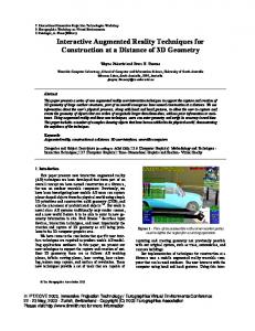
The use of 3D imaging techniques has been early adopted in the footwear industry. In particular, 3D imaging could be used to aid commerce and improve the quality and sales of shoes. Footwear customization is an added value aimed not only to improve product quality, but also consumer comfort. Moreover, customisation implies a new business model that avoids the competition of mass production coming from new manufacturers settled mainly in Asian countries. However, footwear customisation implies a significant effort at different levels. In manufacturing, rapid and virtual prototyping is required; indeed the prototype is intended to become the final product. The whole design procedure must be validated using exclusively virtual techniques to ensure the feasibility of this process, since physical prototypes should be avoided. With regard to commerce, it would be desirable for the consumer to choose any model of shoes from a large 3D database and be able to try them on looking at a magic mirror. This would probably reduce costs and increase sales, since shops would not require storing every shoe model and the process of trying several models on would be easier and faster for the consumer. In this paper, new advances in 3D techniques coming from experience in cinema, TV and games are successfully applied to footwear. Firstly, the characteristics of a high-quality stereoscopic vision system for footwear are presented. Secondly, a system for the interaction with virtual footwear models based on 3D gloves is detailed. Finally, an augmented reality system (magic mirror) is presented, which is implemented with low-cost computational elements that allow a hypothetical customer to check in real time the goodness of a given virtual footwear model from an aesthetical point of view.
Keywords
Augmented reality in footwear sector; stereoscopic vision for design and display of footwear; 3D gloves for footwear design.
1. Introduction
New technologies for achieving competitive advantages The search for competitive advantages has been a constant feature of the footwear industry, which has become more intensive in recent years in view of the emergence of new competitors from different places in the world. The reduction in manufacturing costs is no longer the key for this search; instead, the objective currently pursued is related to an increase in the quality of the final product and the customisation or small-scale ad-hoc manufacturing. Customisation can be achieved either by obtaining a
1
1 2 3 4 5 6 7 8 9 10 11 12 13 14 15 16 17 18 19 20 21 22 23 24 25 26 27 28 29 30 31 32 33 34 35 36 37 38 39 40 41 42 43 44 45 46 47 48 49 50 51 52 53 54 55 56 57 58 59 60 61 62 63 64 65
shoe adapted to the anatomical features of a user’s foot [Olivato et al., 2007] [Xiong et al., 2010] [Zhang et al., 2011] [Wang et al., 2011] [Nishiwaki, 2011], or by adapting it aesthetically to the customer’s liking [Luh et al., 2012] [Fatur and Dolinsek, 2009]. New technologies have become the essential tools to achieve these objectives. Realistic 2D vision is a well-consolidated standard in the industry, and for some years now research has been focusing on the use of stereoscopic vision at different production stages, including displaying the finished product to the consumer. Virtual and Augmented Reality in designing and manufacturing processes The term virtual reality is defined as a set of technologies that allow a user to interact with a computer simulated environment, whether the environment is a simulation of the real world or an imaginary world [Khan et al., 2011]. Normally, it is possible to experiment with this virtual environment using a conventional monitor or other devices compatible with stereoscopic vision. Furthermore, [Azuma et al, 2001] described augmented reality as a phase between absolute reality and absolute virtuality, which has the following properties: a) it combines real and virtual or augmented objects; b) it runs interactively and in real time; and c) it aligns real and augmented objects with each other. The three-dimensional representation of the product provides a higher degree of realism. This factor has been implemented at different stages of production processes in order to improve productivity and product quality. For instance, at the product creation stage, the concurrent design review by different engineers can be more efficient if virtual reality and augmented reality tools are used, as stated by [Sidharta, 2006]. This paper also set out an augmented reality environment shared by several designers with tangible user interfaces (TUI) integrating digital information with physical objects and environments. Users wearing HMD or head-mounted-displays can capture the real physical world and the system can augment it using virtual objects. Since virtual objects are coupled to physical objects, these must be tracked using a set of markers attached to them, which are tracked and interpreted by the ARToolkit library. Virtual objects can be rotated, translated, assembled or disassembled by means of voice commands. The visualization of the virtual world does not necessarily require a HMD or a similar device. In many cases, users do not bring with them the vision system. Instead, a monitor-based configuration displaying stereo images is used, for which the user shall wear specific glasses for stereoscopic vision. This is the case of the ARGOS (Augmented Reality through Graphic Overlays on Stereovideo) system, developed at the University of Toronto to work in environments with poor visibility [Milgram et al., 1995] [Dracsic et al., 1993] [Khan, 2011] proposed developing a virtual manufacturing system as an application of augmented reality to improve several process stages, including quality control, human-machine interface and information flows, practicing e-commerce and possibility of implementing different production philosophies. [Oh et al., 2006] presented the Direct Modelling approach, which allows the user to intuitively select geometric entities in real time regardless of the modifications made. This was initially developed for conceptual design and architectural planning [Fiorentino, 2010]. [Fiorentino, 2002] showed the advantages derived from using a semi-immersive environment, combining stereoscopic vision with 3D inputs, addressed to conceptual and aesthetic design. [Lee et al., 2009] proposed embedding augmented reality into the rapid prototype of a digital product, and special attention was given to those aspects that are of interest for the consumer: tangibility, functionality and aesthetics. A rapid prototype of the product is created with which it is possible to interact using a simple and cheap tangible pointer instead of using more expensive hardware interfaces, all this visualized in a three-dimensional collaborative environment. Augmented reality approaches have also been proposed for automotive services [Lee and Rhee, 2008], for the design of flexible manufacturing systems [Gausemeier et al., 2002], for architectural design and urban planning [Broll et al., 2004]. Interfaces for virtual worlds
2
1 2 3 4 5 6 7 8 9 10 11 12 13 14 15 16 17 18 19 20 21 22 23 24 25 26 27 28 29 30 31 32 33 34 35 36 37 38 39 40 41 42 43 44 45 46 47 48 49 50 51 52 53 54 55 56 57 58 59 60 61 62 63 64 65
With regard to the interface that allows the interaction with the objects from the virtual world, the use of gloves stands out, both for the manipulation of objects and for commands. [Lee et al., 2010] used hand gesture and vibrotactile feedback. Using a sensorised glove, the user can grab and point at virtual objects; one of the gloves is configured as the dominant one to manipulate objects, while the other is used to choose options from the different system menus. The gloves feature microprocessors, LED, a wireless system for communicating with the main computer, and some conductive patches mounted on the finger tips and the palm. The possible actions are indicated by different finger positions with respect to the hand palm, which are detected through the connections of the conductive patches. [Buchmann et al., 2004] used an interaction system based on markers mounted on hands and fingers to track the user’s gestures, as well as haptic feedback devices. The main contribution of this work is that this approach allows users to interact with virtual objects using natural hand gestures. This system, FingARTips, employs visual tracking to detect a set of simple gestures based on the artificial vision library ARToolkit. The gloves feature markers on the thumb, index finger and the base knuckles of both fingers, with which the location and orientation of the hand in the 3D environment is accurately tracked. Gesture recognition is based on finger position relative to the scene. [Yi et al., 2009] detailed the characteristics of an augmented reality system for the design of architectural models. The generation of different objects is based on the detection of hand movements and gestures. The left hand is used to make semantic signs for each building unit within a hierarchy, while the right hand is used to sketch the geometry using a pen-marker. The movement of both hands is detected through a motion capturing system made up of MotionAnalysis© and EVaRT R4.6 in order to subsequently analyse and detect the corresponding gesture. [Thomas and Piekarski, 2002] and [Hoang et al., 2009] analysed an interaction system in an outdoor augmented reality environment, called Tinmith-Hand. Users can work in a collaborative environment for which they have a HMD and a pair of pinch gloves. Pinch gloves are used to select options from the system menus. Each option has a finger assigned to select it by making a pinch gesture with the thumb and the corresponding finger. In addition, in order to capture the spatial coordinates of the user’s hands, thumbs are provided with small markers in such a way that the virtual objects on the scene are selected according to the hand position. [Hosoya et al., 2003] proposed an interaction system in which the user could touch virtual objects rendered in a monitor using a marker mounted on his/her finger. Virtual and Augmented reality applied to footwear industry It is difficult to find well-documented research papers on virtual or augmented reality applied to the footwear industry. There is, for instance, the work of [Rupérez et al., 2010]; however, their contribution mainly focused on the analysis of the user’s foot morphology and modelling a suitable shoe taking the shoe upper and the pressure withstood in different areas of the foot as the basic criteria. [Greci et al., 2012] showed the characteristics of a haptic device simulating the internal volume of a shoe, called FootGlove. It is a sort of insole that adapts to the user’s foot through a mechatronic mechanism. This allows four essential dimensions of the last to be obtained, from which the customized shoe is designed by the customer. However, this device is not directly integrated with an augmented reality system. [Mottura et al., 2003] [Redaelli et al., 2009] detailed the characteristics of an augmented reality system applied to footwear. It is a magic mirror for in-shop footwear customisations. First of all, the user’s foot is scanned taking five basic parameters. Starting from an initial configuration, the user can co-design his/her shoes choosing certain aspects such as the type of leather, the colour, the sole, etc. The system features an LCD display acting as a mirror, a camera that captures shots in real time of the user’s feet, and a tracking system to compute in real time the position and orientation of feet. One of the drawbacks of this system is that it requires wearing special socks in order for the foot position and orientation to be detected, as well as using a special carpet on which the user shall move.
3
1 2 3 4 5 6 7 8 9 10 11 12 13 14 15 16 17 18 19 20 21 22 23 24 25 26 27 28 29 30 31 32 33 34 35 36 37 38 39 40 41 42 43 44 45 46 47 48 49 50 51 52 53 54 55 56 57 58 59 60 61 62 63 64 65
[Eisert et al., 2008] proposed a virtual mirror system for the real-time visualisation of customized sports shoes. The client can change the design and colours of a shoe model at a special terminal and add individual embroideries and decorations. There is no need for markers on the shoes. The system mainly consists of a display and a camera mounted close to the display looking down to capture the client’s feet. The camera captures and transfers the images with a resolution of 1024x768 pixels. Each shoe model consists of different sub-objects composed of triangle meshes which can be replaced to create different geometries. One of the drawbacks of this system is the lack of robustness under different lighting conditions, which requires the floor in front of the camera to be painted in a special colour to allow the use of the chroma-keying technique for segmentation. The maximum rate achieved by the visualisation system is 35 frames per second; however, there is no reference to the complexity of rendering models (number of polygons), which makes it difficult to check its efficiency. The purpose of this paper is to present some of the advances made in Augmented and Virtual Reality techniques used in the footwear sector. All the steps forward taken try to seek high performance using low-cost equipment. This paper is structured in the following sections: section 2 describes a stereoscopic vision system specializing in the visualisation of complex footwear models; section 3 presents a Virtual Reality system for footwear design using data gloves; section 4 describes an Augmented Reality system (magic mirror) aimed at complex footwear models. Finally, section 5 presents the main conclusions drawn and a list of references used.
2. High-quality stereoscopic vision system for footwear
Stereoscopy is a technique for creating or enhancing the illusion of depth using two images of the same scene but captured from different angles, just like human eyes see the world. For this reason, it is necessary to work with two images simultaneously, so the whole process that is normally carried out for a monoscopic image will double in the case of a stereoscopic image. It is then required to calculate the offset in relation to the point where the camera is allegedly located, which shall capture a certain scene for both viewpoints, the left and the right one. This offset will also imply a change in the angle of vision incidence on the scene, so this calculation is not elementary although it is well known in the field of computer vision [Southard, 1992]. Parameters for the calculation of projections For the calculation of projections, there are certain parameters to be taken into consideration (see figure 1). These can be summarised as follows:
Intraocular distance: It is the distance between the two points from which the image is captured. These points are normally determined using as the centre point the one from which the image would be captured in the monoscopic mode. It should be possible to modify this value according to the person who is seeing the image, since everyone has a different distance between the eyes. This distance is usually 65 mm, but it can range from 45 mm to 75 mm.
Projection plane: It is the plane on which the elements making up the scene are located and will be captured.
Distance to the projection centre: It is the perpendicular distance from the centre point located between the two points from which both images will be captured to the projection plane.
Parallax: It depends on the above factors and is the distance between the two projections of a point located on the projection plane. Thus changing the parallax determines the depth at which
4
1 2 3 4 5 6 7 8 9 10 11 12 13 14 15 16 17 18 19 20 21 22 23 24 25 26 27 28 29 30 31 32 33 34 35 36 37 38 39 40 41 42 43 44 45 46 47 48 49 50 51 52 53 54 55 56 57 58 59 60 61 62 63 64 65
the objects are located in relation to the projection plane. There will be no parallax for a point located on the very projection plane; there will be positive parallax for a point located behind the projection plane, and there will be negative parallax for a point located in front of the projection plane.
Far plane
Screen viewport Screen IOD/2
Near plane Frustum shift
Centre eye viewpoint
Right eye viewpoint
Half of Intraocular distance (IOD/2)
Figure 1. Diagram showing the operation of stereoscopy and its parameters 2. 1 Basic outline for drawing with quad buffering In a computer-aided monoscopic vision system, a drawing system based on double buffering (back and front buffers) is used to enhance vision performance. Such system follows the operation outline shown in the left part of table 1. Although there are other techniques to produce stereoscopic images, there is no doubt that one of the most efficient is the one that replaces double buffering with quad buffering (double buffering for each eye). Table 1. Tasks involved in monoscopic and stereoscopic vision Monoscopic drawing process with double buffering
Stereoscopic drawing process with quad buffering
Clearing the back buffer.
Clearing the left back buffer. Clearing the right back buffer
Drawing the scene to the back buffer.
Calculating the left viewpoint and drawing the scene to the left back buffer. Calculating the right viewpoint and drawing the scene to the right back buffer.
Swapping back and front buffers.
Swapping back and front buffers
Quad buffering requires graphic hardware able to support this system in order to achieve optimum performance. Therefore, stereoscopic vision systems use a similar drawing outline to that of monoscopic
5
1 2 3 4 5 6 7 8 9 10 11 12 13 14 15 16 17 18 19 20 21 22 23 24 25 26 27 28 29 30 31 32 33 34 35 36 37 38 39 40 41 42 43 44 45 46 47 48 49 50 51 52 53 54 55 56 57 58 59 60 61 62 63 64 65
systems, but the process is repeated twice and buffers are swapped once as a final step, as shown in the right part of table 1. 2.2 Experiments with CAD software for footwear A stereoscopic vision system has been developed based on the the footwear design and manufacturing software 3D+®, which is widespread on the market. This software allows the realistic visualisation of models and their modification to produce all types of footwear. For this reason, the footwear models used feature a high definition, sometimes exceeding 0.5 million polygons. Such high definition provides images with great realism but in turn implies a serious handicap for performance in that there is the risk for the image not to be viewed in real time if the required hardware is not available. In view of the high accuracy, precision and performance requirements, we opted for quad buffering with hardware support, using OpenGL® graphic library. The devices used are described below. Hardware -
PC equipped with an nVidia® Quadro 600 graphic card
We used a desktop computer with an Intel i5 processor, 4GB RAM memory and nVidia® Quadro 600 graphic card (see Figure 2) equipped with 96 graphic processors (cores) with quad buffering support. Nevertheless, any card provided with Quadbuffer technology may be valid for the use of the stereoscopic vision system. Said technology is the one provided by nVidia’s Quadro® range. In this case, we opted for one of the cheapest models of said range. With regard to the software, we used the operating system 64-bit Windows 7 Professional and the development platform CodeGear C++ RAD Studio 2007. -
3D Monitor
In order to be able to view good-quality stereoscopic images, it is necessary to have a monitor able to display two images simultaneously. There are two technologies available on the market able to produce said effect: double frequency monitors and double display monitors. The former feature better quality image but in turn require using glasses synchronised with the monitor to alternately cover the eyes (active glasses). The latter produce less definition images but require polarised glasses, which are simpler and more comfortable for the user. For this prototype, we used a double frequency LED 3D monitor developed by BENQ® with different refresh rates to be selected (60Hz, 100Hz, 110Hz and 120Hz), so it can perfectly operate either in monoscopic or in stereoscopic mode and adapt the refresh rate to ambient light conditions. This way, given that the lighting inside buildings often operates at 50 Hz, it would be advisable to select 100 Hz (multiple of 50) to avoid excessive eye strain; while for ambient light, 120 Hz would be the most adequate option. Of course, any 3D monitor can be used for stereoscopic vision. In addition, 3D projectors or TVs can be used, as long as they have connectors compatible with those of the output connectors of the graphic card used. -
nVidia® 3DVision Pack
The nVidia 3dVision pack (see figure 2) comprises a pair of active glasses and an infrared (IR) emitter. By means of a driver, the graphic card synchronises the monitor refresh rate with the IR emissions in such a way that the IR emitter sends the signals to the glasses so that they can activate the shutters. The reach of the IR signal is limited and the emitter shall be visible to the glasses. There are other more expensive alternatives operating in the same way, but they replace IR with radiofrequency for communicating, which provides further reach and allows various glasses to be simultaneously synchronised, even if they are not directly located in front of the emitter.
6
1 2 3 4 5 6 7 8 9 10 11 12 13 14 15 16 17 18 19 20 21 22 23 24 25 26 27 28 29 30 31 32 33 34 35 36 37 38 39 40 41 42 43 44 45 46 47 48 49 50 51 52 53 54 55 56 57 58 59 60 61 62 63 64 65
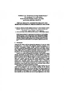
Figure 2. Hardware used: nVidia® Quadro 600 graphic card and nVidia 3DVision® pack Performance experiments A battery of experiments was carried out to check the performance of the stereoscopic vision system. For this, different footwear models with different definition were used. Figure 3 shows some of the rendered models.
Figure 3. Some of the footwear models used for the experiments. As shown in Figure 3, the models featured high precision, even reaching 600,000 polygons in the case of the ladies’ model. The visualisation performance is shown on the right side of the graph (in frames per second) for the same models. Using the quad buffering technique, it was possible to reach real time values even for the heaviest model (24 frames/s).
Figure 4. Complexity of the models and performance of the vision system. It is to be noted that in stereoscopic vision, one frame equals two monoscopic renderings, so the performance achieved was significantly good. In the case of the ladies’ model, even though it featured
7
1 2 3 4 5 6 7 8 9 10 11 12 13 14 15 16 17 18 19 20 21 22 23 24 25 26 27 28 29 30 31 32 33 34 35 36 37 38 39 40 41 42 43 44 45 46 47 48 49 50 51 52 53 54 55 56 57 58 59 60 61 62 63 64 65
twice as many polygons, the performance was not reduced by half thanks to the action of the multicore card, which increases its performance with large amounts of information. The whole system proved to provide a high-quality image and agility in the interaction with models thanks to the high fps rate achieved. Figure 5 shows some shots of the whole system in operation. The pictures show the “double image” effect caused by the superimposition of images for the left and right eye. This effect can be avoided with the use of active glasses; in fact, the right photo shows how the left eye was being covered letting the right eye see the image when the photo was taken.
Figure 5. Example of a three-dimensional model displayed in stereoscopic mode; left: detailed view of the quad buffer stereo image; right: whole system using active glasses.
3. Virtual manipulation system using 3D gloves
Virtual Reality is a technology based on the use of computers and other devices aiming to produce the appearance of reality to make users feel they are present in it. Some equipments are complemented with suits and gloves equipped with sensors specifically designed to simulate the perception of different stimuli, which intensify the feeling of reality. Despite being initially focused on videogames, its application has extended to many other fields, such as medicine and flight simulators. The virtuality concept establishes a new way of relating the use of space and time coordinates, overcoming spatial-temporal barriers and configuring an environment in which information and communication are accessible from hitherto unknown perspectives at least in terms of volume and possibilities. Virtual Reality allows the generation of interactive environments that separate the need to share the space-time dual, thus facilitating in this case new contexts for the exchange of information and communication. Currently, the use of different Virtual Reality control peripherals like gloves is increasing exponentially thanks to the videogame industry and the technological evolution that nowadays allows new control techniques to be developed. This section presents a development that incorporates into CAD/CAM footwear design systems a Virtual Reality control functionality using a sensorised glove. 3.1 Resources used Desktop computer The same PC used for the previous section was used: a i5® Intel processor with 4GB RAM, an nVidia Quadro 600 graphic card, and 64-bit Windows 7 operating system.
8
5DT Virtual reality glove
1 2 3 4 5 6 7 8 9 10 11 12 13 14 15 16 17 18 19 20 21 22 23 24 25 26 27 28 29 30 31 32 33 34 35 36 37 38 39 40 41 42 43 44 45 46 47 48 49 50 51 52 53 54 55 56 57 58 59 60 61 62 63 64 65
The Virtual Reality glove developed by the company 5DT was also used, which can be seen in Figure 6.
Figure 6. 7-sensor Virtual Reality glove developed by the company 5DT The glove used had 5 flexion sensors (one for each finger) as well as 2 rotation (pitch and roll) sensors that allow its inclination to be known. The glove offers individualised information for each of the sensors it has. Figure 7 shows the sensor monitoring interface showing the standard level of flexion of each finger as well as the inclination in both senses of the hand (pitch and roll). This information is treated by the software to produce the virtual effects shown below.
Figure 7. Right: interface to monitor the information provided by the glove; left: glove and sensor location. 3.2 Control functionality using the glove From the point of view of the CAD/CAM software, the glove was used for two different purposes. The first one consisted in simulating a movement of the design object. Currently, the industrial CAD systems carry out these movements using the mouse complemented with a key to produce different types of movements. The movements mostly used are the trackball, which makes three-dimensional rotations of the object around its centre, and the scroll, which moves the object on the three-dimensional space. The second purpose consisted in recognising certain gestures made by the hand to perform some common operation in the software: orthogonal positioning, material selection... Both functionalities are described in more detail below.
9
Virtual tracking
1 2 3 4 5 6 7 8 9 10 11 12 13 14 15 16 17 18 19 20 21 22 23 24 25 26 27 28 29 30 31 32 33 34 35 36 37 38 39 40 41 42 43 44 45 46 47 48 49 50 51 52 53 54 55 56 57 58 59 60 61 62 63 64 65
As previously stated, in this mode of operation the glove will make movements of the object that were previously done using different combinations of keys and the mouse. Given that the glove is a peripheral that is continuously informing the system of the position of the sensors, it is necessary to intuitively specify the system as to when it should activate the tracking and when to stop doing it. Here, the activation/deactivation of the tracking was carried out through the recognition of two different gestures; also a third gesture was added on the thumb to differentiate the trackball movement from the scroll movement.
(1)
(2) (3) (4) where r and p are the angular values of roll and pitch respectively,
is the inverse matrix of the
perspective transformation, c is the centre of the object to be transformed,
is a scroll matrix to c.
The gestures and their operation are the following: 1. Fist Gesture (the five fingers folded, see figure 8a). This gesture, simulating the action of picking up an object, will be used to activate sensor tracking and perform the trackball movement. Once the fist is closed, the displayed model will be able to be rotated in the active window through the use of the inclination values (pitch and roll) provided by the glove. These values are used to determine two rotation angles of the object in 3D on its centre. For this, two rotation matrices are made: MR is obtained with the roll angle value and makes a rotation on the 3D axis that projects the vertical axis of the screen (see expressions 1 and 3) and Mp with the pitch value carries out a rotation on the 3D axis that results from the projection of the horizontal axis of the screen (see expressions 2 and 3). Finally a global transformation matrix MT is made (see expression 4) that is used to modify the pile of transformations from the visualisation system. 2. Thumb Gesture (the thumb stretched out and the rest folded, see figure 8b). With the tracking function active, this gesture will be used to activate the scrolling mode. Once this gesture is done, the displayed model will be able to be moved in the active window through the use of the inclination (pitch and roll) values provided by the glove. 3. Palm Gesture (the five fingers stretched out). This gesture will be used to deactivate the tracking mode of the glove. Once the hand is completely open, the user will not be interacting with the model loaded in the application. This gesture is, therefore, the base gesture to use when one does not want the inclination information of the glove to have an effect on the transformations that the displayed model can experience in the active window (see figure 8c).
10
1 2 3 4 5 6 7 8 9 10 11 12 13 14 15 16 17 18 19 20 21 22 23 24 25 26 27 28 29 30 31 32 33 34 35 36 37 38 39 40 41 42 43 44 45 46 47 48 49 50 51 52 53 54 55 56 57 58 59 60 61 62 63 64 65
a) Start tracking & trackball
b) Scrolling
c) Stop tracking
Figure 8. Implemented virtual tracking modes
a)
b)
c)
Figure 9. Positioning gestures: a) azimuthal positioning, activated using the index finger, b) front positioning, activated using index and middle fingers, c) lateral positioning, activated using index, middle and ring fingers.
11
Virtual Positioning
1 2 3 4 5 6 7 8 9 10 11 12 13 14 15 16 17 18 19 20 21 22 23 24 25 26 27 28 29 30 31 32 33 34 35 36 37 38 39 40 41 42 43 44 45 46 47 48 49 50 51 52 53 54 55 56 57 58 59 60 61 62 63 64 65
The gestures that are shown in figure 9 have been configured to make different orthogonal views: 1. Index Gesture (index finger stretched out, the rest folded). This gesture (associated to the value of number 1) serves to establish the first of the orthogonal views in the window, showing the model on the XY plane (see figure 9a). 2. Index and middle gesture (Index and middle fingers stretched out, the rest folded). This gesture (associated to the value of number 2) serves to establish the second of the orthogonal views in the window, showing the model on the YZ plane (see figure 9b). 3. Index, Middle and Ring Gesture (index, middle and ring fingers stretched out, the rest folded). This gesture (associated to the value of number 3) serves to establish the third of the orthogonal views in the window, showing the model on the XZ plane (see figure 9c). Calibration The glove calibration is important given that each person can open and close their fingers in a different way when making gestures; therefore the glove must be recalibrated each time a new person is to use it. To calibrate, the flexion thresholds of the digital sensors must be known and also the gestures recognised by the glove must be redefined. The calibration is completed visually through an application (see figure 10a) where bars appear that show the level of amplitude of the sensor value during the process of moving the fingers from an open position, to a closed one. Once the flexion range has been defined for each finger, the opening and closing thresholds must be selected to allow the recognition of the different gestures by the glove (see figure 10b). There is an option within the application to save calibrations or upload them and thus have various calibrations available according to the user. The gestures are configured, once the finger flexion thresholds have been defined, indicating the flexion position that should be reached by each finger. b)
a)
Figure 10. Calibration of the glove: a) sensor range; b) sensor threshold for the fist gesture recognition
12
1 2 3 4 5 6 7 8 9 10 11 12 13 14 15 16 17 18 19 20 21 22 23 24 25 26 27 28 29 30 31 32 33 34 35 36 37 38 39 40 41 42 43 44 45 46 47 48 49 50 51 52 53 54 55 56 57 58 59 60 61 62 63 64 65
Figure 11. Virtual glove system for footwear design. The whole system in operation is shown in figure 11. This system can be complemented with the stereo vision technique described in the previous section to increase the user’s feeling of immersion.
4. High quality augmented reality system for footwear (magic mirror) An Augmented Reality Magic Mirror consists in a user’s capture and display, to which virtual elements are added so that the user can be seen in his/her own environment but with elements that, in reality, do not physically exist. This utility is currently beginning to be used in sectors like accessories or cosmetics. As discussed in the introduction section, there are systems developed for footwear although they basically have two drawbacks: the lack of flexibility and the slowness for high resolution images. This section details the making of an experimental prototype of a Magic Mirror specific for footwear whose main novelty lies in the dissociation of the visual capture of the user’s referential environment. 4.1 Structure of the system The prototype of the magic mirror for footwear (patent pending) developed is shown in figure 12. The main difference with other similar systems lies in the use of an IR camera to detect the object concerned, in this case the user’s foot. The advantage that this camera brings is that the segmentation of the image is much simpler and faster and, therefore, the software can detect, in real time, the location of the foot regardless of the resolution of the camera that is filming the real scene. To locate the position of the user’s foot, IR (LED type) markers of 0.5 W were used. Contrary to other augmented reality systems, the use of IR markers is much more discreet, because of their size almost invisible to the user and can be easily adapted to the foot. Also, having their own light makes them less sensitive to lighting or shadow changes of uncontrolled systems as for instance a footwear store.
13
1 2 3 4 5 6 7 8 9 10 11 12 13 14 15 16 17 18 19 20 21 22 23 24 25 26 27 28 29 30 31 32 33 34 35 36 37 38 39 40 41 42 43 44 45 46 47 48 49 50 51 52 53 54 55 56 57 58 59 60 61 62 63 64 65
a d
b
c
e
Figure 12. Structure of the Magic Mirror prototype: a) high resolution camera b) IR camera c) computer with footwear design software d) high resolution monitor e) IR LED diodes With regard to the camera that captures the scene, the only limitations are those of the associated hardware, since its quality will not affect the system’s performance. In most augmented reality systems only one camera is used; therefore, if the quality of the image is very high, the time taken by the system to segment the image and locate the foot increases considerably. Furthermore, the quality of the virtual scene (virtualised model) cannot be too high because it would also compromise the system’s response time. The components of the developed prototype are detailed below: Desktop computer The same desktop computer used in the previous sections was used: an i5 intel processor, 4GB of RAM and a nVidia Quadro 600 graphic card with 64-bit Windows 7 operating system. Scene capturing camera This camera was used exclusively to film the real scene; therefore, it did not condition the system’s performance. A Web LG Webpro2 LIC-300® camera with a resolution of 1024 x 768 pixels was used in the experiments. IR camera To locate the position of the user’s foot, the IR camera was used, which incorporated the Wiimote® remote controller from the Nintendo Wii® game console (see Figure 12). It is a low-cost device (approx. 40€) that also has software libraries that facilitate the automatic segmentation of the image, giving information on the position of IR light sources. Contrary to what happens when acting with the game console, the Wiimote is fixed and the IR emitter moves in order for the remote to act as a camera detecting the positioning and orientation of the emitter. Emitting device For this first version of the prototype, the emitting device used was comprised of 4 LED diodes of 0.5 w of power arranged on a printed circuit board (see Figure 14). Obviously, the device had to be subsequently adapted so that the emitting devices could be placed on the user’s foot without the risk of them moving or being detached when the user was moving his/her feet. Both the size of these LEDs (2
14
1 2 3 4 5 6 7 8 9 10 11 12 13 14 15 16 17 18 19 20 21 22 23 24 25 26 27 28 29 30 31 32 33 34 35 36 37 38 39 40 41 42 43 44 45 46 47 48 49 50 51 52 53 54 55 56 57 58 59 60 61 62 63 64 65
mm of diameter) and their low consumption allowed ensuring that the final device would be able to incorporate button-type batteries so that it is autonomous, discreet and easy to place on the user’s foot.
Figure 13. Wiimote® device and a view of the IR signal emitting prototype 4.2 System operation As briefly mentioned in the introduction of this section, Augmented Reality is a mixed reality that groups and links virtual elements with actual elements of the environment. For this, the virtual elements are placed and rendered on a series of base images captured from the real world. This base will require a device able to capture the images that make it up. When it comes to establishing a coherent real-virtual position relationship it is necessary to take two aspects into account: Regarding the IR camera, a stable capture configuration must be established to be able to determine the position of each LED at any time; in other words, it is to be anticipated that the LED points can be temporarily hidden in certain positions of the foot and therefore their real position in case of concealment must be estimated. Furthermore, this two-dimensional point capture information provided by the IR segmentation must be extrapolated in order to be converted into three-dimensional information that indicates what type of transformations have to be done on the virtual model so that it seems to be positioned on the image of the real foot. For this, different calculations are done that will require nonvariable characteristics both in the IR emitter and in the camera that captures them. This will be addressed in the following sections. 4.2.1 Estimating points in the event of concealment The IR LED diodes are the landmarks that the system uses to locate the user’s foot in the environment. Therefore, the identification of these 2D points in the IR camera is essential. It may occur that due to the user’s movements or environmental interferences, part of the diodes can be hidden from the infrared camera. In such case, it is necessary to estimate the position of the non-visible points so that the system has the most reliable information possible of the user’s foot location at all times. In each camera capture a correspondence of the closest points with regard to the previous capture was performed. If the number of points captured was smaller than the number of LEDs, an estimation was performed following a minimisation procedure of an error function that used the conjugate gradient method (see expressions 5-7). The error function had the parameters given in table 2. It was about deducing the movement that took place on the visible LEDs to estimate the movement made by the nonvisible ones.
15
Table 2. IR movement estimation parameters.
1 2 3 4 5 6 7 8 9 10 11 12 13 14 15 16 17 18 19 20 21 22 23 24 25 26 27 28 29 30 31 32 33 34 35 36 37 38 39 40 41 42 43 44 45 46 47 48 49 50 51 52 53 54 55 56 57 58 59 60 61 62 63 64 65
Parameter
Description
tx ty
Translation in the horizontal and vertical axes respectively
α
Rotation angle value in the capture plane with respect to the centre of the window
sx sy
Scale factors for the horizontal a vertical axes respectively
Once the values that minimise the error function in the conjugate gradient method had been found, the transformation that appears in the expression X was applied to each one of the non-visible points.. (5) (6) (7) where V represents the group of visible points in the current capture and V -1 the group of V points corresponding to the previous capture Once the function’s minimum had been found, the transformation of the expressions (5) and (6) was applied to the non-visible points. The tests carried out show that the method is suitable for possible LED concealment. 4.2.2 Calculating the 3D position and orientation Another important issue is the correspondence between the 2D points captured by the IR camera and the 3D ones visualised in the virtual environment. The problem lies in finding a geometric and perspective transformation that places the real elements detected in the virtual image so that, by superimposing both, the illusion that the virtual element is embedded in the real scene is generated. In general, the problem is analytically resolved using a system of equations in accordance with homography concepts [Simon et al., 2000]. Table 3. Parameters for the estimation of foot’s position and orientation. Parameter
Description
tx, ty, tz
Translation on the Cartesian axes
α
Rotation angle value on the v vector
vx vy vz
Components of the rotation vector
In this research and for performance reasons, an alternative solution to the analytical method was chosen, by minimising an error function, using for this the conjugate gradient method. This is a fast method where the solution is approximate. This approach was adequate for the problem, since the exact solution was not necessary as it was only intended to track in real time. Also, having the previous solution (previous frame) considerably accelerated the convergence of the method.
16
1 2 3 4 5 6 7 8 9 10 11 12 13 14 15 16 17 18 19 20 21 22 23 24 25 26 27 28 29 30 31 32 33 34 35 36 37 38 39 40 41 42 43 44 45 46 47 48 49 50 51 52 53 54 55 56 57 58 59 60 61 62 63 64 65
To establish the correspondence, there were two sets of points available. On the one hand, the 2D points captured by the IR image (hereinafter, ) and on the other hand, the 3D points placed on the virtual model ( ). Each camera capture established a correspondence between the IR points detected and their 3D equivalents associated to the virtual model. For this, the error function that appears in expression 9 was minimised. This error function had seven parameters given in table 3.
Figure 14. System in operation, at the right of the monitor the IR segmentation can be seen. The sensitivity of the photo camera allows the IR light of the device to be captured. The objective was to find the geometric transformation that made the 3D points of the virtual world place themselves on the 2D points captured (see expression 8). The process involved three transformations: a three-dimensional rotation of α radians on a free vector , called ; a generic three-dimensional translation set of points equivalent to the IR points
. The
and
transformations ensured that the
could be placed anywhere in the virtual space and with any
orientation, simulating the movement that the IR device would have in the real scene. The matrix given by the current values of the rendering system.
was
The correspondence was achieved by simulating a positioning of the 3D points that was equivalent to the 2D ones obtained using an IR camera. The minimisation of the function that appears in the expression 9 was intended to give the values of the geometric transformation that superimposed the virtual points on the real ones. The solution obtained would also be used as a starting point to obtain the solution for the following frame.
(8) (9)
17
where P represents the perspective transformation matrix of the rendering system,
1 2 3 4 5 6 7 8 9 10 11 12 13 14 15 16 17 18 19 20 21 22 23 24 25 26 27 28 29 30 31 32 33 34 35 36 37 38 39 40 41 42 43 44 45 46 47 48 49 50 51 52 53 54 55 56 57 58 59 60 61 62 63 64 65
radians rotation on the vector
and
a matrix of alfa
a translation matrix on the Cartesian axes of values tx, ty, and
tz. 4.3 System performance In order to carry out the experiments, the same parameters and models used in section 2.1 were used. The specific IR capture hardware and the camera are shown in section 4.1.
Figure 15. Complexity of the models and system performance. The whole system showed a great agility in the interaction and precision with the models thanks to the high fps rate reached. Figure 16 shows an image of the whole system in operation. As observed in figure 15, the models have great precision, the ladies’ model exceeding the 600,000 polygons. The right side of the graph shows the visualisation performance (in frames per second) for the same models. Thanks to the use of the estimation methods based on the conjugated gradient, it was possible to easily obtain real time values even for the heaviest model (30.1 frames/s).
Figure 16. System performance test 5. Conclusions
18
1 2 3 4 5 6 7 8 9 10 11 12 13 14 15 16 17 18 19 20 21 22 23 24 25 26 27 28 29 30 31 32 33 34 35 36 37 38 39 40 41 42 43 44 45 46 47 48 49 50 51 52 53 54 55 56 57 58 59 60 61 62 63 64 65
The footwear sector is a traditional sector that is quite reluctant to the use of new technologies. It is a sector dominated by Small and Medium sized companies (SMEs) that cannot afford the expensive high computational capacity equipments. In general, standard, low cost hardware is used by these companies. Here, we find CAD/CAM software operating on low cost equipment, which does however require high computational effort. As an example, it can be said that 3D models are made up of NURBS surfaces that can have hundreds of thousands of control points. In conclusion, any technique or method that is intended for introduction in this software should be efficient. This research work has presented a series of AR and VR techniques adapted to real footwear design software that has high quality and precision requirements. First of all, a stereoscopic rendering system is presented. This system gives the user the illusion of physically seeing the virtual shoe model. For a CAD designer, this tool will provide valuable information in order to interact with the model precisely. For the consumer, stereoscopic vision improves the product display by adding realism. Thanks to the quad buffering technique employed, it has been possible to obtain real time (24 frames/s) values for the heaviest shoe model (600,000 polygons), while with other models a performance of 38 frames/s can even be reached. Secondly, a 3D interface using gloves is presented. This interface allows the designer to perform a more intuitive and effective interaction with the 3D environment. Besides, the use of 3D gloves allows hand gesture recognition in order to perform the most common tasks. Finally, a magic mirror system for shoes is shown. A camera captures the customer’s image trying a virtual shoe on. This way, the customer can see himself/herself wearing a virtual shoe. There are other similar systems available in the sector, but the novelty of this one lies in the dissociation of recognition and rendering by using two cameras instead of just one. An IR camera performs the detection, and a high resolution camera captures the scene. The result is a real time system that implements an augmented reality tool which makes it possible to work with a higher level of detail for both shoe models and scenes. All of the new advances presented in this paper are included in commercial footwear software spread worldwide. The footwear models used for the experiments have been provided by the Spanish Footwear Technological Institute (INESCOP). This work has been supported by the Valencian Government in the framework of the project IMDEEA/80. 6. References [Azuma et al., 2001] Azuma, R., Baillot, Y., Behringer, R., Feiner, S., Julier, S., and MacIntyre, B. (2001) Recent advances in augmented reality. Computer Graphics and Applications, IEEE Volume 21 , Issue 6 [Broll et al., 2004] Broll, W., Lindt, I., Ohlenburg, J., Wittkämper, M., Yuan, C., Novotny, T., Schiecky, A.F., Mottramy, C., and Strothmannz, A. (2004) ARTHUR: A Collaborative Augmented Environment for Architectural Design and Urban Planning. Proceedings of International Conference on Humans and Computers 2004: 102-109. [Buchmann et al., 2004] Buchmann, V., Violich, S., Billinghurst, M., and Cockburn, A. (2004) FingARtips – Gesture Based Direct Manipulation in Augmented Reality. Proceedings of the 2 nd International conference on Computer graphics and interactive techniques in Australasia and South East Asia: 212 – 221. [Dracsic et al., 1993] Dracsic, D., Grodski, J.J., Milgram, P., Ruffo, K., Wong, P. and Zhai, S. (1993) ARGOS: a Display System for Augmenting Reality. Proceedings of INTERCHI,93: Human Factors in Computing Systems, Amsterdam, The Netherlands, 24-29. [Eisert et al., 2008] Eisert, P., Fechteler, P., and Rurainsky, J. (2008) 3-D Tracking of Shoes for Virtual Mirror Application. Proc. IEEE Conf on Computer Vision and Pattern Recognition, Achorage, Alaska, June 2008. [Fatur and Dolinsek, 2009] Fatur, P. and Dolinsek, S. (2009) Mass Customization as a Competitive Strategy for Labour Intensive Industries. Advances in Production Engineering and Management 4(1):77-84.
19
1 2 3 4 5 6 7 8 9 10 11 12 13 14 15 16 17 18 19 20 21 22 23 24 25 26 27 28 29 30 31 32 33 34 35 36 37 38 39 40 41 42 43 44 45 46 47 48 49 50 51 52 53 54 55 56 57 58 59 60 61 62 63 64 65
[Fiorentino et al., 2010] Fiorentino, M., Uva, A.E., Dellisanti Fabiano, M., and Monno, G. (2010) Improving bimanual 3D input in CAD modelling by part rotation optimization. Computer-Aided Design, Volume 42, Issue 5:462–470 [Fiorentino et al., 2002] Fiorentino, M., de Amicis, R.; Monno, G.; Stork, A. (2002) Spacedesign: a mixed reality workspace for aesthetic industrial design. Proceedings. of the International Symposium on Mixed and Augmented Reality, ISMAR2002. [Gausemeier et al., 2002] Gausemeier,. J., Fruend, J., and Matysczok. C. (2002) AR Planning tool: designing flexible manufacturing systems with augmented reality. Proceedings of the 8 th Eurographics Workshop on Virtual Environment; 19-25. [Greci et al., 2012] Greci, L., Sacco, M., Cau, N., and Buonanno, F. (2012) FootGLove: A Haptic Device Supporting the Customer in the Choice if the Best Fitting Shoes. EuroHaptics 2012, Part I, LNCS 7282: 148-159. [Hoang et al., 2009] Hoang, T.H., Porter, S.R., and Thomas, B.H. (2009) Augmenting Image Plane AR 3D Interactions for Wereable Computers. Proceedings of the 10 th Australasian User Interface Conference (AUIC2009), Wellington, New Zealand. [Hosoya et al., 2003] Hosoya, E., Kitabata, M., Sato. H., Harada, I., Nojima, H., Morisawa, F., Mutoh, S., and Onozawa, A. (2003) A mirror metaphor interaction system: touching remote real objects in an augmented reality environment. Proceedings of the 2nd IEEE and ACM International Symposium on Mixed and Augmented Reality, pp. 350, Washington, USA, 2003. [Khan et al., 2011] Khan, W.A., Abdul Raouf, A., and Cheng, K. (2011) Virtual Manufacturing, Springer-Verlag, London. [Lee et al., 2010] Lee, J.Y., Rhee, G.W., and Seo, D.W. (2010) Hand gesture-based tangible interactions for manipulating virtual objects in a mixed reality environment. The International Journal of Advanced Manufacturing Technology, Volume 51, Numbers 9-12:1069-1082 [Lee et al., 2010] Lee, J.Y., Rhee, G.W., and Seo, D.W.(2010) Hand gesture-based tangible interactions for manipulating virtual objects in a mixed reality environment. The International Journal of Advanced Manufacturing Technology, Volume 51, Numbers 9-12:1069-1082 [Lee et al., 2009] Lee, J.Y., Rhee, G.W., and Park, H. (2009) AR/RP-based tangible interactions for collaborative design evaluation of digital products. International Journal of Advanced Manufacturing 45:649-655. [Milgram et al., 1995] Milgram, P., Dracsic, D., Grodski, J.J., Restogi, A., Zhai, S., and Zhou, C. (1995) Merging Real and Virtual Worlds. Proceedings of IMAGINA’95, Montecarlo, Monaco, pp:218-230. [Mottura et al., 2003] Mottura, S., Greci, L., Sacco, M., and Boër, C.R. (2003). An Augmented Reality System for the Customized Shoe Shop. Proceedings of the 2nd interdisciplinary world congress on mass customization and personalization, Munich, Germany. [Nishiwaki, 2011] Nishiwaki, T. (2011) Footwear Fitting Design. In Emotional Engineering, Springer-Verlag, London: 345-363. [Oh et al., 2006] Oh, J., Stuerzlinger, W., and Danahy, J. (2006) SESAME: Towards better 3D conceptual design systems. Proceedings of the 6th conference on designing interactive systems. 2006 [Olivato et al., 2007] Olivato, P., Morricone, M., Fubini, E., and Re, A. (2007) Foot Digitalization for Last Design and Individual Awareness of Personal Foot Characteristics. Digital Human Modeling , Lecture Notes in Computer Science, 2007, Volume 4561/2007, 949-958 [Redaelli et al., 2009] Redaelli, C., Pellegrini, R., Mottura, S., and Sacco, M. (2009) Shoe customers’ behaviour with new technologies: the Magic Mirror case. 15th International Conference on Concurrent Enterprising, ICE 2009, Leiden, The Netherlands, June 22-24
20
1 2 3 4 5 6 7 8 9 10 11 12 13 14 15 16 17 18 19 20 21 22 23 24 25 26 27 28 29 30 31 32 33 34 35 36 37 38 39 40 41 42 43 44 45 46 47 48 49 50 51 52 53 54 55 56 57 58 59 60 61 62 63 64 65
[Rupérez et al., 2010] Rupérez, M.J., Monserrat, C., Alemany, S., Juan, M.C, and Alcañiz, M. (2010) Contact model, fit process and foot animation for the virtual simulator of the footwear comfort. Computer-Aided Design 42:425-431. [Sidharta et al., 2006] Sidharta, R., Oliver, J., and Sannier, A. (2006) Augmented Reality Tangible Interface for Distributed Design Review. Proceedings of the International Conference on Computer Graphics, Imaging and Visualisation (CGIV'06) [Simon et al., 2000] Simon, G., Fitzgibbon, A.W., Zisserman, A. (2000) Markerless tracking using planar structures in the scene. Proceedings of the IEEE and ACM International Symposium on Augmented Reality 2000 (ISAR 2000), pp.120-128 [Southard, 1992] Southard, D. (1992) Transformations for stereoscopic visual simulation. Computers & Graphics 16(4):401–410 [Thomas and Piekarski, 2002] Thomas, B.H. and Piekarski, W. (2002) Glove Based User Interaction Techniques for Augmented Reality in an Outdoor Environment. Virtual Reality 6: 167-180. [Wang et al., 2011 ] Wang, J., Zhang, H., Lu, G., and Liu, Z. (2011) Rapid parametric design methods for shoe-last customization. The International Journal of Advanced Manufacturing Technology, Volume 54, Numbers 1-4: 173186 [Xiong et al., 2010 ] Xiong, S., Zhao, J., Jiang, Z., and Dong, M. (2010) A computer-aided design system for footfeature-based shoe last customization. The International Journal of Advanced Manufacturing Technology , Volume 46, Numbers 1-4, 11-19 [Yi et al., 2009] Yi, X., Qin, S., and Kang, J. (2009). Generating 3D architectural models based on hand motion and gesture. Computers in Industry 60: 677-685.
21